question

dnwalker avatar image
dnwalker asked

Why doesn't my shunt go to 100%

I have the problem that my SmartShunt never goes to 100%.

I have a LifePo4 battery that currently has 27.09V (of course read from the shunt)

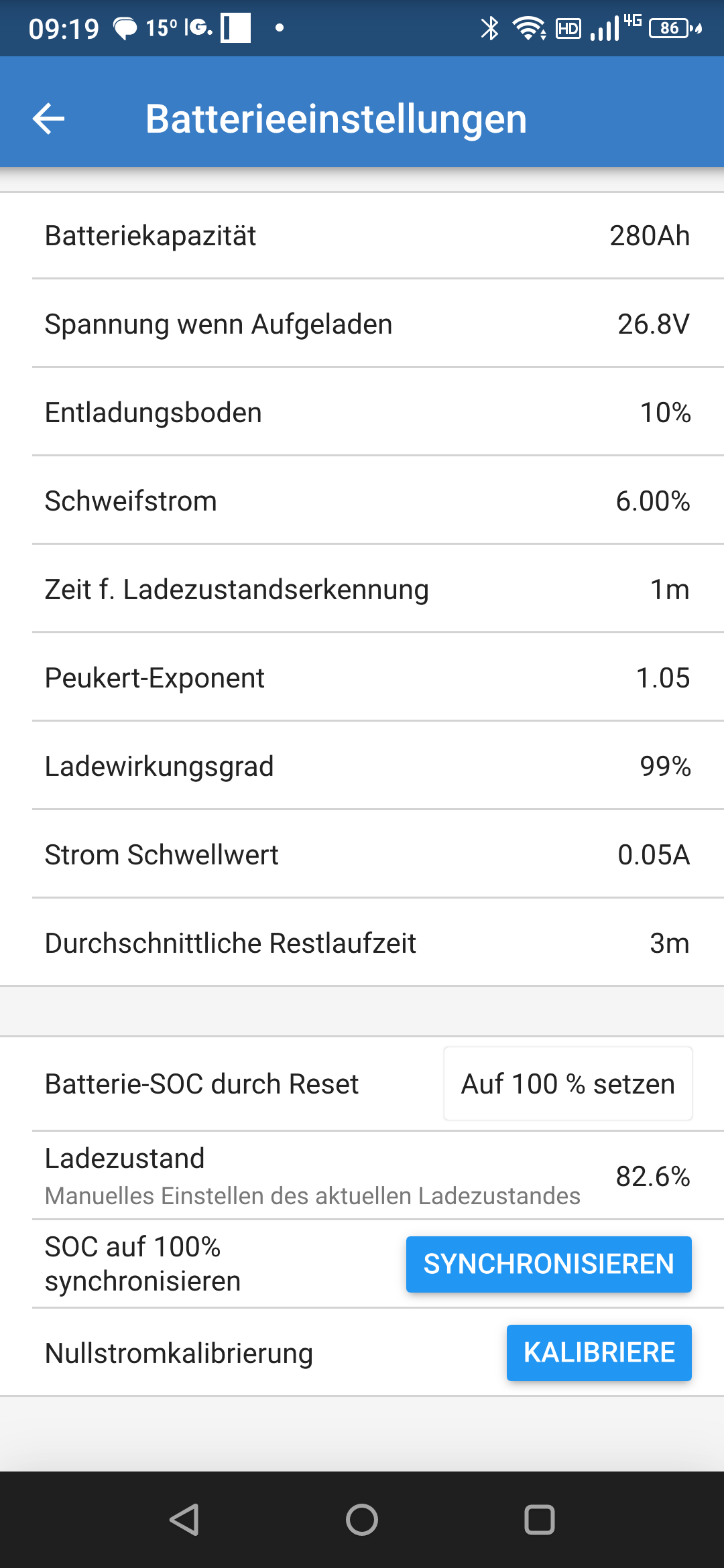
I set the end-of-charge voltage to 26.8V and the acquisition time to 15 minutes.

It is a 280Ah battery and I have the tail current at 0.8%.

Now there are two small consumers on the battery that currently draw 0.6A. The current is also displayed at the shunt with -0.6A.

As far as I understood, the battery should be displayed after 15 minutes at 100% or am I wrong?

My battery management shows the battery as 100% but unfortunately not the shunt.

The value is simply not set to 100%. It would be nice if you had a solution for me.

Thanks and regards

dieter

SmartShunt
2 |3000

Up to 8 attachments (including images) can be used with a maximum of 190.8 MiB each and 286.6 MiB total.

11 Answers
pwfarnell avatar image
pwfarnell answered ·

Does your shunt measure and display the current when you are charging and increase the SOC. If it does not then you have the charger connection wrong. The charger negative MUST be connected to the system side of the shunt. Thrre must only be one connection to the battery negative and that is the shunt battery terminal. All other negative connections go to the system terminal on the shunt.

If the SOC is increasing during charging but not reaching 100% then your SmartShunt settings need changing. Please post a screenshot of your settings and please confirm what absorption voltage your charger is set at.

2 |3000

Up to 8 attachments (including images) can be used with a maximum of 190.8 MiB each and 286.6 MiB total.

dnwalker avatar image
dnwalker answered ·
Yes, the charging current is displayed and also positive.
The discharge current for me when the solar cells are useless is displayed as -0.6A.
Then the polarity should be correct.
1 comment
2 |3000

Up to 8 attachments (including images) can be used with a maximum of 190.8 MiB each and 286.6 MiB total.

pwfarnell avatar image pwfarnell commented ·
Not a wiring problem then, it will be to do with the settings on the SmartShunt compared to your charging voltage. Please attach a screenshot of your SmartShunt settings and let us know what your absorption voltage is.
0 Likes 0 ·
seb71 avatar image
seb71 answered ·

SmartShunt SOC gets to 100% either after all 3 synchronization conditions are met (simultaneously) or after enough energy gets into the battery.


Tail current set as 0.8% is too small for reliable SOC synchronization to 100%.


The voltages you list are also low (if your LiFePO4 is 8 cell).

What are you charger settings (Absorption Voltage especially)?

2 |3000

Up to 8 attachments (including images) can be used with a maximum of 190.8 MiB each and 286.6 MiB total.

dnwalker avatar image
dnwalker answered ·

Hello,

I have set the maximum cell voltage to 3.5V in my BMS directly on the battery. I didn't want to go to the upper limit of the end-of-charge voltage to protect the battery. I also set 28V as the absorption voltage on my solar charger. Float voltage is set to 27.1V. In the Smartshunt I have the voltage when charged at 26.8V. I had now set this voltage very low to see why the shunt does not jump to 100%. Over the loading time, the display also goes to 100% at some point, but not over 100% recognition.

2 |3000

Up to 8 attachments (including images) can be used with a maximum of 190.8 MiB each and 286.6 MiB total.

seb71 avatar image
seb71 answered ·

I also set 28V as the absorption voltage on my solar charger

This is relatively OK. It's a safe value, but the BMS might not be able to do much cell equalization (if your BMS does that).

Float voltage is set to 27.1V.

This is somewhat high. I would set Float Voltage at 26.8V.

-------

In the SmartShunt I have the voltage when charged at 26.8V.

For testing it is OK, but for normal usage it is too low. Try something like 0.2V lower than the Absorption Voltage set in the charger. So in this case 27.8V.


the acquisition time to 15 minutes

This is way too long. Try 5 minutes instead. Even 3 minutes for Summer time with clear sky.


I have the tail current at 0.8%.

This is way too low, as I wrote in my previous post. Try something like 3% - 4%.


In order for the SmartShunt to synchronize the SOC to 100%, your battery voltage needs to be above "charged voltage" for the set time, while the charging current must be below the tail current value you set.

If any condition is not met, it will not synchronize.


With your values, the voltage condition (>26.8V) is easy to met, but the duration (15 minutes) and tail current (<2.28A) conditions will not be easily met (while charging at 28V) unless you get some heavy clouds after absorption stage started.

2 |3000

Up to 8 attachments (including images) can be used with a maximum of 190.8 MiB each and 286.6 MiB total.

dnwalker avatar image
dnwalker answered ·

Thanks for the information. I am currently testing the shunt with the settings you mentioned. I have now set the detection time to 1 minute to even get a reaction from the shunt. You can observe the values for one minute and see for yourself whether all the conditions are met so that the part switches to 100%. The thing is currently not working properly.

2 |3000

Up to 8 attachments (including images) can be used with a maximum of 190.8 MiB each and 286.6 MiB total.

dnwalker avatar image
dnwalker answered ·

Unfortunately, I'm still having trouble resetting to 100% charge. My battery is currently fully charged and the BMS has completely switched off the current flow into the battery. A current of 2-3A flows from the battery. This is also displayed in the shunt with -2.66A. The measured voltage at the shunt is 27.98V and I set the detection time to 1min. In that case, the shunt should switch to 100% charge - shouldn't it? Unfortunately, the shunt stops at 83%. I set the tail current to 6%. I can't explain the behavior.screenshot-20230805-091916.png

screenshot-20230805-091931.png


2 comments
2 |3000

Up to 8 attachments (including images) can be used with a maximum of 190.8 MiB each and 286.6 MiB total.

klim8skeptic avatar image klim8skeptic ♦ commented ·

@dnwalker @Sten you might want to tell your BMS that it is ok to acept charge to 3.55v/cell. The BMS seems to disable charge (?) before the 3 parameters for the shunt to sync to 100%.


Of course, set the mppt to 3.5v bulk/absorp, 3.375v float.


0 Likes 0 ·
seb71 avatar image seb71 commented ·

A current of 2-3A flows from the battery. This is also displayed in the shunt with -2.66A. The measured voltage at the shunt is 27.98V and I set the detection time to 1min. In that case, the shunt should switch to 100% charge - shouldn't it?

No. The current must flow into the battery.

0 Likes 0 ·
Sten avatar image
Sten answered ·

I have the same problem with my setup. What happens in my system is that the BMS stop charging when the battery reach 14V.

It does'nt hold the voltage at 14V but change it to float 13,5v without any absorption. That means that the shunt does'nt have time to meet the condition, even with the lowest time setting 1 min.

I think you have a simmilary problem. The solution is to set the charged voltage just below the float voltage. A flaw with that is that the shunt can syncronize earlyer than wanted.

5 comments
2 |3000

Up to 8 attachments (including images) can be used with a maximum of 190.8 MiB each and 286.6 MiB total.

seb71 avatar image seb71 commented ·

What happens in my system is that the BMS stop charging when the battery reach 14V.

It does'nt hold the voltage at 14V but change it to float 13,5v without any absorption.

That's not normal (no absorption stage).

One possible cause could be very different cell voltages near the top (near full).

0 Likes 0 ·
Sten avatar image Sten seb71 commented ·

@Seb71 in my system it is perfecly normal. It has run about 2 years now without any problems. The diference in cell voltage is less than 0,010V. It is a REC ABMS and there are no absorption voltage.

screenshot-20230805-114336-vrm.jpg

screenshot-20230805-114356-vrm.jpg

0 Likes 0 ·
seb71 avatar image seb71 Sten commented ·
LiFePO4 cell voltages when not full/close to full (or empty/close to empty) are not that relevant.


In your graph no cell reaches even 3.5V. Except a short spike to about 3.48V-3.49V, those voltages are all under 3.45V (most of the time under 3.40V).

1 Like 1 ·
klim8skeptic avatar image klim8skeptic ♦ Sten commented ·
@Sten when your charger quits charging at 13.9v, the battery is still taking 20a of charge current.


Your battery is not fully charged.

0 Likes 0 ·
Sten avatar image Sten klim8skeptic ♦ commented ·
It's not an isue. I delibrely have it this way, when the voltage rise there is only about 2% of capacity to full charge.
0 Likes 0 ·
dnwalker avatar image
dnwalker answered ·

We don't really need to discuss whether the charging parameters are suitable for a battery or not. My parameters are set that way for certain reasons and I don't want to change anything. Of course, if you set the standard profiles for the respective battery type in the shunt, the display will never jump to 100%. However, I did not use these fixed profiles but made my own settings in the expert menu. If the three conditions are then met, should the shunt jump to 100% or am I wrong?

I set 26.8V as the end-of-charge voltage and the current reading is 27.98V, so the first condition is met. I set the current to 6%. That would be 16.8A with a capacity of 280A. For me, the current is in the minus range, so the condition should also be met. The detection time is one minute and I also waited the time and the part does not switch to 100%. So where is the mistake? I can't get any further with this part.

2 |3000

Up to 8 attachments (including images) can be used with a maximum of 190.8 MiB each and 286.6 MiB total.

seb71 avatar image
seb71 answered ·

If the three conditions are then met, should the shunt jump to 100% or am I wrong?

I set 26.8V as the end-of-charge voltage and the current reading is 27.98V, so the first condition is met. I set the current to 6%. That would be 16.8A with a capacity of 280A. For me, the current is in the minus range, so the condition should also be met. The detection time is one minute and I also waited the time and the part does not switch to 100%. So where is the mistake? I can't get any further with this part.


I already wrote that the current must be into the battery.


So at least one condition is not met => no SOC synchronization to 100%.


2 |3000

Up to 8 attachments (including images) can be used with a maximum of 190.8 MiB each and 286.6 MiB total.

dnwalker avatar image
dnwalker answered ·

I've already read that. At the time I took the screenshot, some power was already draining from the battery. Before the screenshot, of course, the battery was charged and a positive current was displayed.

If the current is less than 16.8A, it should be switched to 100%. Even with a current of 10A, the shunt did not switch to 100%

2 comments
2 |3000

Up to 8 attachments (including images) can be used with a maximum of 190.8 MiB each and 286.6 MiB total.

seb71 avatar image seb71 commented ·

Before the screenshot, of course, the battery was charged and a positive current was displayed.

Why didn't you took screenshots in that situation, then?

In all your posts you always talk about "small discharge current".

And your screenshot shows that the battery is discharging.


True that mathematically -2.66<16.8, but there needs to be a CHARGING current (shown with a positive sign). The +/- signs are just a convention for the current flow direction (into the battery or out from the battery).


Synchronization only happens during charging, never during discharging.

If for a split second you have discharging, the synchronization timer resets to zero (starts again from zero).

0 Likes 0 ·
Sten avatar image Sten commented ·
There are 3 condition to be meet. The voltage above charged voltage and the current bellow the current set at least the time set. So if your voltage not stay above the set carged voltage at least for the time set in your shunt, it wont syncronize.
0 Likes 0 ·