question

Stormy R. avatar image
Stormy R. asked

Multiplus 2, how to wire K1 open collector to control relay?

Okay, I've just found out that on the Multiplus 2 K1 is actually an open collector rather than a relay like it was on the Multiplus 1. The open collector is to me a confusing device but it appears it can serve the same function that the old relay used to, with a bit of work.


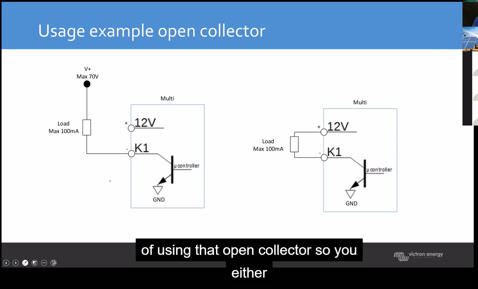
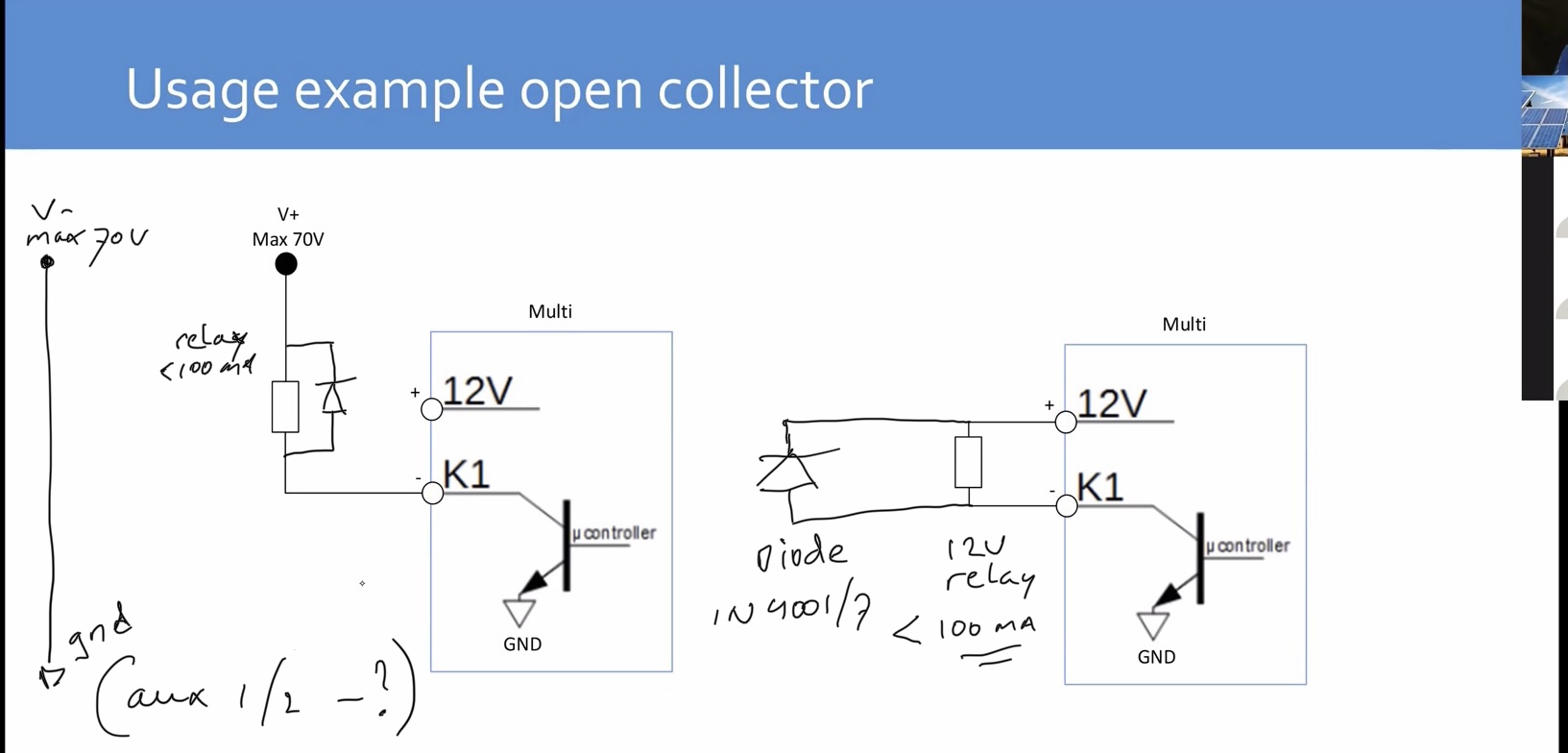
It seems that open collectors are suitable as an on off switch for a circuit, and that I need only to connect an external relay and power source. And that K1 can be programmed to break and close the power circuit to the relay.


I've read some posts saying that a diode needs to be included in that circuit or else the transistor in the open collector will fry. I don't quite understand why...

Does anyone have an example wiring diagram of how to use the K1 open collector to control a relay?

Multiplus-IIwiringRelay
1 comment
2 |3000

Up to 8 attachments (including images) can be used with a maximum of 190.8 MiB each and 286.6 MiB total.

multiplusinus avatar image multiplusinus commented ·

As an Electronic Technician I can say that this appears to be a good answer. Using a diode across the coil as shown (called a snubber) will help keep the reverse EMF voltage spike that occurs when a magnetic field collapsed in a relay coil from destroying the solid-state device that is providing the open collector output.

Here is some information that I discovered by playing with the MultiPlus K1 relay:

Using the K1 relay in MultiPlus 2:

  1. For it (K1) to work to drive a relay, you have to connect both of the terminals, not just the open collector one. Connect the 12V terminal to one side of the relay coil, and the open collector terminal to the other side of the coil! The 12V relay used should not require >100 mA, or it will not work. Note- I found that using an external 12V power supply and the just open collector output will not work, probably because the grounds are apparently not commoned together!
  2. To activate the K1 relay in the software, use the VE Configure program, then click on the Assistants tab, click on the Add assistant button, click on Relay, then click on Programmable relay. Click on this assistant, click on Start assistant, click on the left arrow, then click on Use secondary programmable relay K1, click on the left arrow and select the desired conditions for operating the K1 relay. You will have to repeat the process laid out in step 2 to add a second programmable relay to properly define both states (open and close) for the K1 relay.
0 Likes 0 ·
2 Answers
duivert avatar image
duivert answered ·

do you already have the aux relay in use? if not you could use it.

see: https://community.victronenergy.com/questions/26331/multiplus-2-programmable-contact-k1.html

for more info on the k1 open collector output

3 comments
2 |3000

Up to 8 attachments (including images) can be used with a maximum of 190.8 MiB each and 286.6 MiB total.

Stormy R. avatar image Stormy R. commented ·

I will already have what they call the "alarm relay" in use and need an additional relay so have been looking at how to properly use the K1 one collector to drive an additional external relay.

If you mean the actually Aux 1 and Aux 2 ports with only 2 terminals each, I thought they were only inputs that could be connected to various devices in various ways to provide the Multiplus 2 unit additional information.

I have just come across this information

https://professional.victronenergy.com/online-training/16/

Right at 27:40 is when she starts talking about the K1 open collector.

usage-of-open-collector.jpg

And here is a slide from that video that ALMOST lays my question to rest. I see that in the post you've linked it is pictures from the same video that are linked. If I am understanding correctly it is explained that the positive K1 terminal on the Multiplus PROVIDES a voltage source. And if you want to use a voltage source over 12volts but under 70v, you will have to connect an external voltage source, in which case the positive K1 terminal IS NOT USED. Quite a mystery how my 48volt multiplus has its own 12volt source to provide but this appears to be what is being stated.

In either case what is not explained in the video is the use of a diode. I have since unearthed some more research. Why do I need to use a diode in conjunction with my relay if i am using K1 open collector to control it? Simplified explanation, energy builds up in the switch of the relay while it is energized, more energy than the K1 relay can safely handle. When the switch is deenergized that build up has to go somewhere and will find a path out that destroys K1. Using a diode will prevent this and there is a specific way that diode needs to be hooked up.

Other information that helped me understand this subject if that in this case when we are talking about the open collector connecting to ground to turn on the circuit, we are not talking about earth ground. we are actually talking about zero voltage reference which is the battery negative terminal.

However

MY REMAINING QUESTION: She says that when using an external power source the "ground" of that power source needs to be connected to the common "ground" of the multiplus. This is the new point where I am stuck on this problem. I'm not entirely sure what she means and where she means it to be connected to.

Im not sure if in this instance she is talking about the negative wire of the battery, and even if she is im not sure where on the multiplus she wants that connected. unfortunately it doesnt seem to be represented in the diagram. Any help understanding this part would be appreciated.

0 Likes 0 ·
Alexandra avatar image Alexandra ♦ Stormy R. commented ·

@Stormy R.

Look up the use of a snubber diode in home automation.

Or just snubber diode.

0 Likes 0 ·
duivert avatar image duivert Stormy R. commented ·
Hi

Ok, if your relay is already in use then you will need the k1 output, im going to draw you a schematic asap

0 Likes 0 ·
duivert avatar image
duivert answered ·

left is with a 12v relay (check relay specs for current, needs to be below 100mA)


right is with relay and external power supply up to 70v (check relay specs for current, needs to be below 100mA), gnd (-) from exterternal power supply needs to be connect with multiplus gnd (-) i think the aux 1 and 2 (-) is the gnd (not shure, not measured it yet!)

025ac21c-99c9-45ba-aed4-38e6affa80d3.jpeg


always place a diode over the relay coil in opposite direction of + and - as drawn in the schematic, so the induction from the relay coil cant damage the open collector output


2 |3000

Up to 8 attachments (including images) can be used with a maximum of 190.8 MiB each and 286.6 MiB total.

Related Resources