question

rrofes avatar image
rrofes asked

Battery switch gets too hot: would Victron Switch ON/OFF 275A improve things?

Hello community!

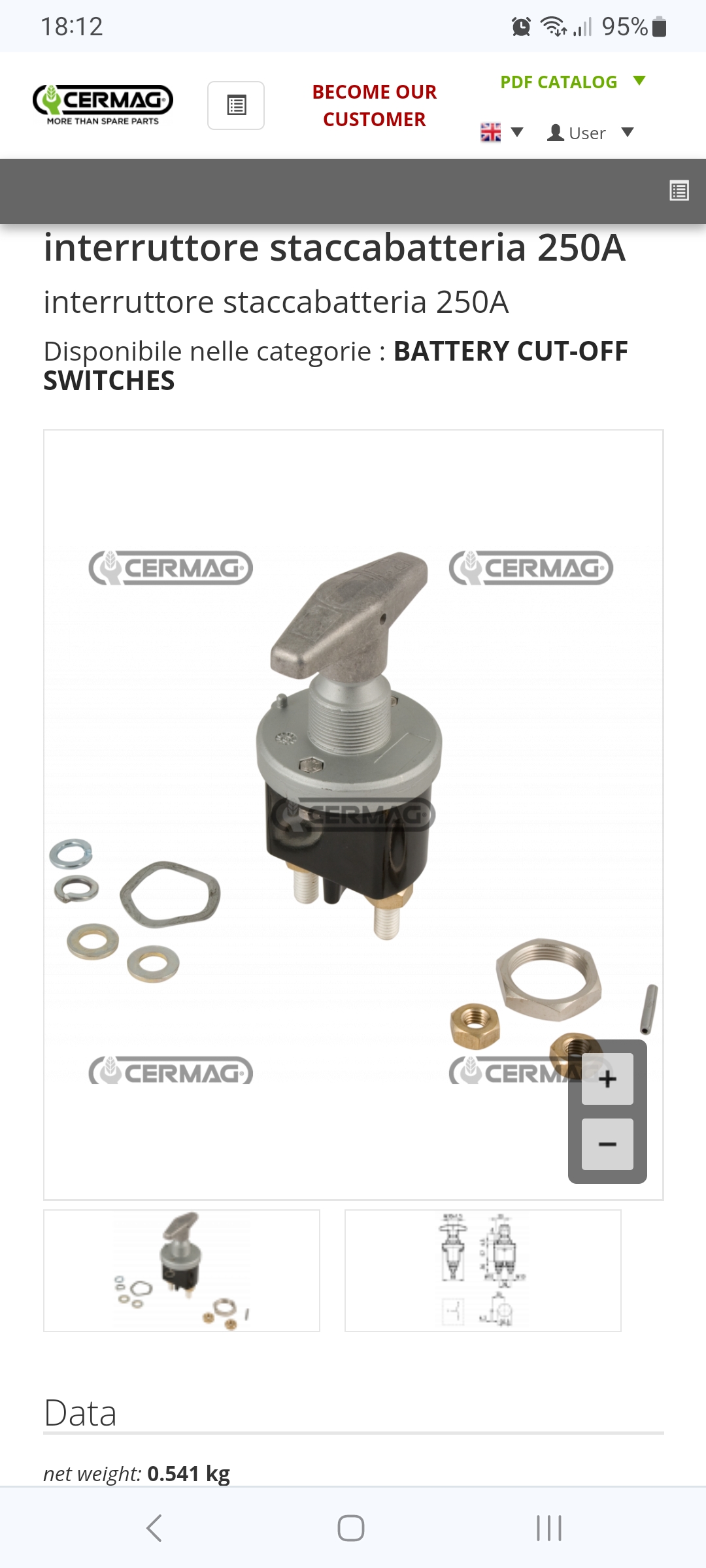
Is anyone using the Victron Battery Switch ON/OFF 275A? https://www.victronenergy.com/battery-isolators-and-combiners/battery-switch-on-off#manuals
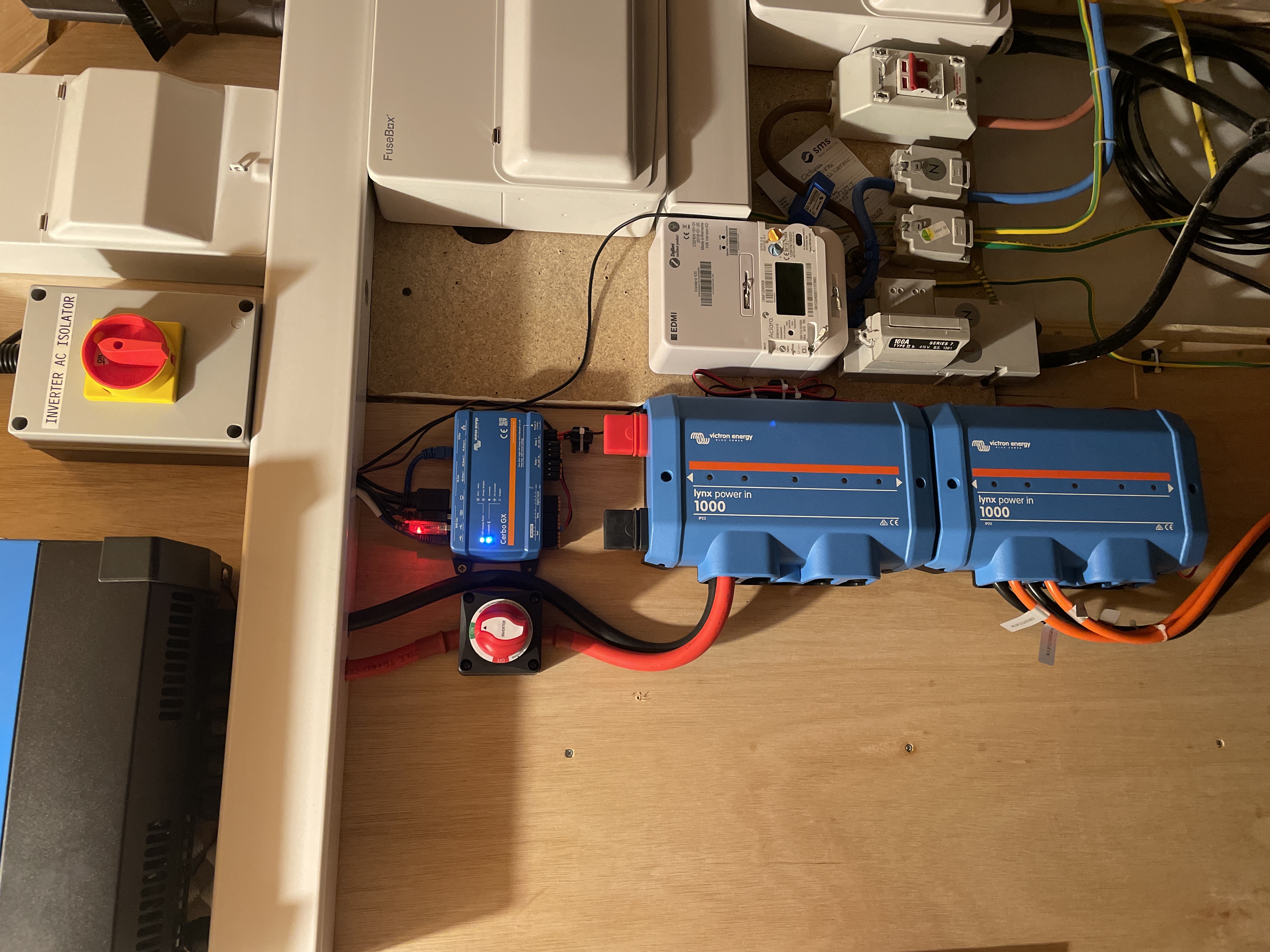
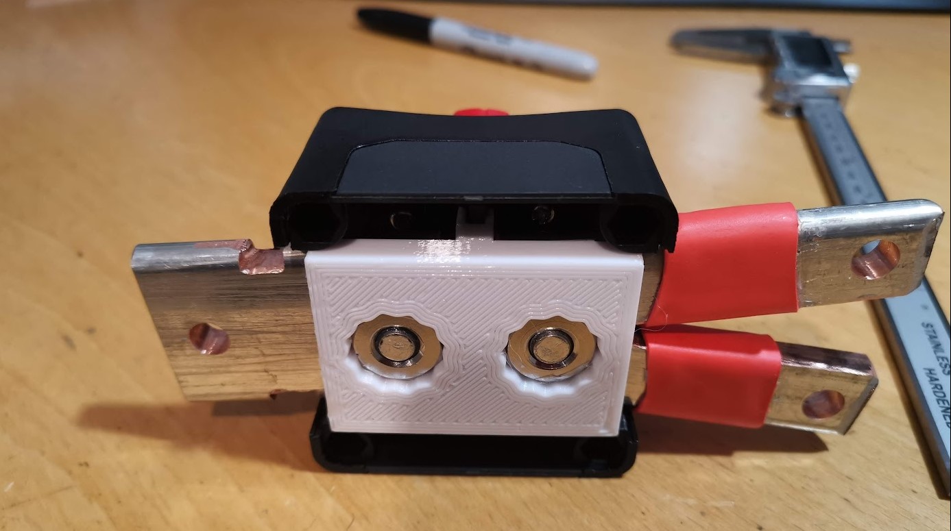
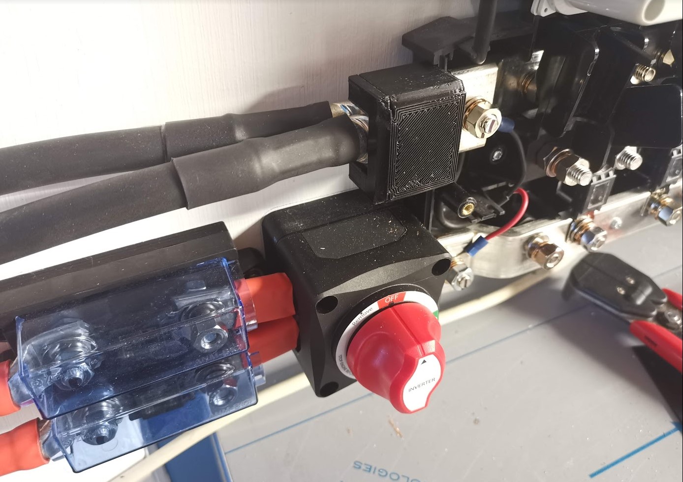
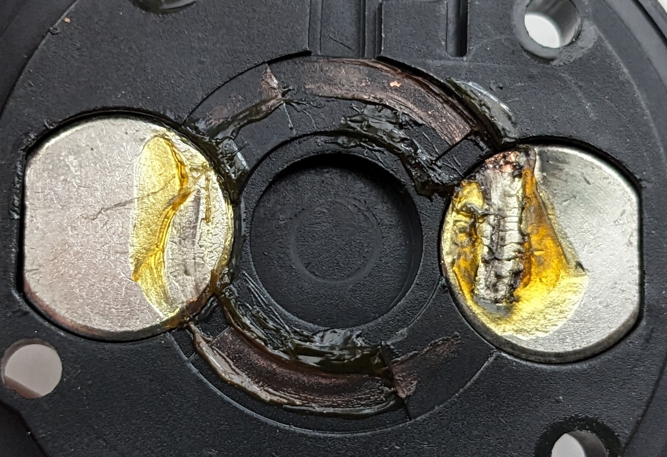
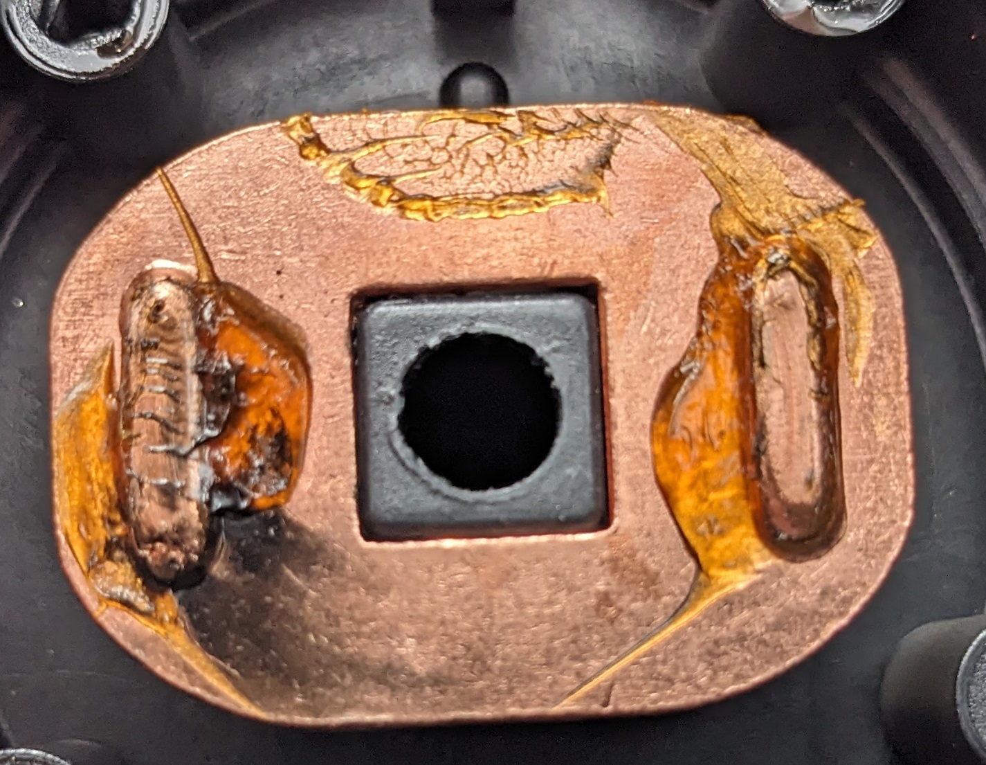
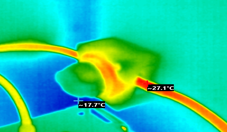
I have used similar looking switches, with similar specs, and my experience is that these get very hot at 48V and 150A (for ambient temp around 20ºC it goes to 110-120ºC). Is that also the case with the original Victron switch? Or can one speak of a better quality? (Switch contact with lower Resistance...)

batteryswitch
2 |3000

Up to 8 attachments (including images) can be used with a maximum of 190.8 MiB each and 286.6 MiB total.

25 Answers
gerard-van-seventer avatar image
gerard-van-seventer answered ·

I'm using this switch but only for 85A. With that the switch stays cold or not more than one or two degrees above ambient. And with even that I suspect my ringlugs as a course of the two degree temperature rise.

2 |3000

Up to 8 attachments (including images) can be used with a maximum of 190.8 MiB each and 286.6 MiB total.

rrofes avatar image
rrofes answered ·

Wow! This sounds good! Any other experience?

2 comments
2 |3000

Up to 8 attachments (including images) can be used with a maximum of 190.8 MiB each and 286.6 MiB total.

ejrossouw avatar image ejrossouw commented ·

1682443114840.png

This is at approx 53A and 21 degrees C ambient. Can go up to about thirty degrees at 85A, but seldomly get there with the batteries already fully charged by 10AM on a sunny day despite still only being spring. Pay particular attention to the quality of the lugs, crimps and connections and ensure the bottom nuts are also properly tightened to avoid any loss of full contact between the switch disk and the "bolt's" contact points. A healthy person's body temperature is higher at 37 degrees C so you should be OK. Victron rates them at 48V 275A continuous, 10s CCA of 1250A and intermitted 5min 455A.

1 Like 1 ·
1682443114840.png (361.6 KiB)
rrofes avatar image rrofes ejrossouw commented ·
Thanks for the info and advices!!! :-)
1 Like 1 ·
jetlag avatar image
jetlag answered ·

I also use the "original" Victron Switch rated for 275A, but my installation also uses only about 75A max. With that I have no Problem at all. I used some contact paste for the bolts and checked everyting with an infrared camera to know everything is fine.

2 |3000

Up to 8 attachments (including images) can be used with a maximum of 190.8 MiB each and 286.6 MiB total.

rrofes avatar image
rrofes answered ·

OK, thanks all for your answers! I will test it at 150A and will report results here in a couple of weeks.

1 comment
2 |3000

Up to 8 attachments (including images) can be used with a maximum of 190.8 MiB each and 286.6 MiB total.

kevgermany avatar image kevgermany ♦♦ commented ·
Thanks, please do. I'm about to run them at that level or higher.
1 Like 1 ·
tazer avatar image
tazer answered ·

I have a similar question about those switches. I already have one installed, and when my system is at full discharge load (155A continuous), the switch gets quite warm. I attached one of the provided temperature sensors to the copper bar which is bolted directly to the switch, and it reaches 60°C within minutes (15°C ambient).

Nothing else gets noticeably warmer, just the switch and the attached wiring. I measured the voltage drop on every connection, and the switch (from bolt to bolt on the back) has by far the highest. I also disassembled, cleaned and re-greased my switch, but that made no difference. The contact surfaces look okay, but the copper contactor inside seems a bit small for 275A continuous.

Luckily I'm building a second battery soon, which will split the current draw per switch in half, but I'm still wondering if that amount of heat output is normal.

2 |3000

Up to 8 attachments (including images) can be used with a maximum of 190.8 MiB each and 286.6 MiB total.

rrofes avatar image
rrofes answered ·

Thanks for the report, tazer!

I've been an electronics design engineer for more than 20 years. According to my experience 60ºC is nothing worrying, if it doesn't go higher. But I am wondering which temperature gets at 275A continuous! With a component like this (a heavy duty switch) I would expect a maximum of 100-130ºC and with this temperature, that the switch probably can handle, care must be taken that nobody gets burned touching around. I guess that the maximum resistance is in the contact itself, so there is the drop of voltage and therefore the heat production. The only thing you can do to help taking out this heat is assure a good thermal bridge in the bolts. If these are directly attached to thigh copper bars it should be ok. Only thing I would try is maybe adding some silicone paste before tightening the bolts. Not sure it will help a lot.

Next week I will try to make a test with 200A and report here.

1 comment
2 |3000

Up to 8 attachments (including images) can be used with a maximum of 190.8 MiB each and 286.6 MiB total.

tazer avatar image tazer commented ·
Thank you for the assessment, 60°C max should be manageable. I have a 20x5mm solid copper bar that connects the switch to the fuse above (100mm²), which already absorbs most of the heat. I thought about attaching some cooling fins to that bar, I have some random ones from other projects laying around, but with the second battery running and 80A max the temperature should be much lower already.
1 Like 1 ·
pekkaj avatar image
pekkaj answered ·

I need also a 400A switch so interested to know which one stays cool in all conditions.

2 |3000

Up to 8 attachments (including images) can be used with a maximum of 190.8 MiB each and 286.6 MiB total.

theo74 avatar image
theo74 answered ·

Just never use the Chinese clones of the Victron, BlueSea, etc. they all get hot above 50A continious.

2 comments
2 |3000

Up to 8 attachments (including images) can be used with a maximum of 190.8 MiB each and 286.6 MiB total.

tazer avatar image tazer commented ·
I think mine are genuine Victron switches, they came in a sealed packaging with Victron manual and from a reputable supplier. It doesn't say Victron on the switch itself though, so maybe it is made by another company and then marketed by Victron.
0 Likes 0 ·
theo74 avatar image theo74 tazer commented ·
I understand, maybe the word ‘clone’ was not chosen that handy then. I ment the Chinese versions of battery kill switches, in general sold for about $5,- till $10,- each.
0 Likes 0 ·
rrofes avatar image
rrofes answered ·

Today I installed the new Victron battery switch and made some tests...

If I remember well, the Chinese switch had a voltage drop of 0.2V @ 155A, this means a contact Resistance of 1.29mOhm.
Victron switch has a voltage drop of 0.056V @ 155A, so contact R has 0.36mOhm: Victron switch has a R 3.6 times lower!

I left the equipment charging battery at 150-170A during 15 min and I measured 81°C at one side of the switch, and around 65ºC in the other side. This difference is because I have a 250A fusible near the switch, they are connected by a 10-15cm copper bar. This fuse gets also very hot (110°C) so part of this heat contaminates the switch. I would say that the switch alone would be around 60-70ºC, not more. Much better than with the original Chinese switch.

All measurements have been made at Tamb 22ºC

I will buy a better quality fuse and replace my original that is also budget, and if I can will repeat the tests at 200A.


2 comments
2 |3000

Up to 8 attachments (including images) can be used with a maximum of 190.8 MiB each and 286.6 MiB total.

caesium avatar image caesium commented ·
I was interested in the outcome of this, so I measured my own Victron switch.


My currents are a little lower but they do agree with you, at 40A through the switch I was seeing a drop of 12.6mV, so 0.31mOhm. Pretty close to your measurement.


I do have some of the "clones" as well but they're not currently in circuit. I could probably rig something up again to measure them if any interest.

1 Like 1 ·
jetlag avatar image jetlag caesium commented ·

Yes, if possible, please do some measurements. I'm interested in the results.

0 Likes 0 ·
jetlag avatar image
jetlag answered ·

Did you use some "thermal" paste in between the contact area? Or something to improve the resistance? Improving the resistance with some copper paste (or someting similar) will also improve the thermal flow towards the cables / busbars and with this the heat in the switch itself.

2 |3000

Up to 8 attachments (including images) can be used with a maximum of 190.8 MiB each and 286.6 MiB total.

rrofes avatar image
rrofes answered ·

Yes, I used the regular white silicone paste to improve thermal transfer in the bolts/busbar unions.

2 |3000

Up to 8 attachments (including images) can be used with a maximum of 190.8 MiB each and 286.6 MiB total.

jetlag avatar image
jetlag answered ·

Well, the "regular" white silcone that I know is electrically nonconductive. It might be, that the contact now is worse... A conductive paste, e.g. with copper particles, could improve the contact instead.

I use this paste to improve my high current contacts: ÄRONIX Kontaktpaste CU

What is your experience to that?

1 comment
2 |3000

Up to 8 attachments (including images) can be used with a maximum of 190.8 MiB each and 286.6 MiB total.

rrofes avatar image rrofes commented ·

I understand what you say, but there is no drop of tension in the bolts where I used the silicone, so it looks like it is OK. Will keep your reference for future occasions!


1 Like 1 ·
rrofes avatar image
rrofes answered ·

Today I made measurements with the Victron switch and also with a better quality fuse (ceramic body, ANL type, manufacturer Zeeman, current 250A). These are the results:

155A: (first measurement 09/05/23)
Switch 0.056V -> 0.36mOhm

180A: (today)
Switch 0.093V -> 0.51mOhm
Fuse 0.039V -> 0.22mOhm

230A: (today)
Switch 0.10V -> 0.43mOhm
Fuse 0.15V -> 0.65mOhm

As you can see I get a dispersion of results. Maybe this is due to measuring the current with the app and not with a multimeter (I don't have and adequate tester to measure 200A DC).
It may also be that the resistance is a function of the current (!), in both devices, or in the fuse in particular, because results are very different. Maybe the heat can change its physical/conductive characteristics. However this should be further investigated.

Going to practical aspects, the temperature measurements I made are these: (After 10 minutes of working at 185A)

Switch: 110ºC fuse side - 80ºC other side

Fuse: 102ºC switch side - 65ºC other side

As you can see today the hottest part is the switch (now its R is higher than the fuse R) so the heat contamination from the fuse is lower. The bus bar that connects fuse and switch is shorter than the others so that's why the node switch-fuse gets hotter than the rest. With a better dissipation of heat (longer bus bar) maybe the switch would have 80ºC at both sides.

All measurements have been made at Tamb 22ºC

4 comments
2 |3000

Up to 8 attachments (including images) can be used with a maximum of 190.8 MiB each and 286.6 MiB total.

kevgermany avatar image kevgermany ♦♦ commented ·
​For me the really interesting side is the temperature. HOT.

Seems the fuse has better heat dissipation than the switch.

Is this the Victron switch, or still the no-name?


0 Likes 0 ·
rrofes avatar image rrofes kevgermany ♦♦ commented ·
Victron! Chinese one would had melted.
0 Likes 0 ·
kevgermany avatar image kevgermany ♦♦ rrofes commented ·

Thanks.Just realised I missed that you said it was the Victron switches.

I think mine will be mounted on something that will act as a heat sink.

0 Likes 0 ·
rrofes avatar image rrofes kevgermany ♦♦ commented ·
Good idea!
0 Likes 0 ·
daza avatar image
daza answered ·

I went for the continuous 300amp one so hope that’s ok and I’ve connected it to the Lynx distributor

img-3900.jpeg


img-3900.jpeg (3.5 MiB)
2 |3000

Up to 8 attachments (including images) can be used with a maximum of 190.8 MiB each and 286.6 MiB total.

pekkaj avatar image
pekkaj answered ·

1500A switch for $10, too good to be true? It's not the prettiest one.


2 |3000

Up to 8 attachments (including images) can be used with a maximum of 190.8 MiB each and 286.6 MiB total.

Justin Cook avatar image
Justin Cook answered ·

It's worth noting that some of these switches appear to be being used on 48v nominal systems, so around 56-58V actual, which is beyond the switch's rated handling... this might have something to do with the problems being seen. My experience is that rotary switches should not be used on a 48vNom system.


My suspicion -because I've seen this happen before on my test bench- is that the ~56v arc that occurred when the switch was closed the first time (that's not to even mention any subsequent closings or -even worse- opening under load) damaged the contacts so now it's not making a good connection when closed and is therefore generating heat just like any other poor DC connection.


When these Victron switches were first released, hooking one up on a 48vNom system to see how it'd do was one of my first tests, since I wasn't sure whether the 48v rating meant 48v maximum or 48v nominal; based on my testing, I concluded that the rating is 48v maximum, which means they should be used on a 36vNom or lower battery bank. While I will say that the Victron switch does much better on a 48vNom system than a Blue Sea or BEP switch, it still definitely suffered arc damage to the contacts from even the first closing. I do still use it on test systems from time to time because it hasn't welded itself shut yet, but I know it's only a matter of time!


Always remember that your 48vNom battery bank is not running at 48v actual, so a switch, breaker, or fuse that's only rated to 48v is not appropriate for use in that environment - you need things rated to 56-60v.

2 comments
2 |3000

Up to 8 attachments (including images) can be used with a maximum of 190.8 MiB each and 286.6 MiB total.

Craig Chamberlain avatar image Craig Chamberlain commented ·
I hear what you're saying but I think it depends on what sort of battery modules you are hooking up to it. In my case I'm using a Pylontech US5000 battery which has a built in BMS with soft start so you are supposed to close the isolator BEFORE you start the battery and so there is no surge or arc. Similarly when shutting down, it's possible to shut off the battery before opening the isolator.


That said, I'm not happy with some of the temperature readings people have taken from the Victron isolator and will be looking at my own isolators very carefully to see if they are heating up or not. I don't think they are but I'm going to check voltage drop and temperature at least.

0 Likes 0 ·
Justin Cook avatar image Justin Cook ♦♦ Craig Chamberlain commented ·
I think my point is simply that when using components outside of their rated handling capacities, it's to be expected that the components might behave oddly. As such, I find it better practice to utilize components that are properly rated for a given system (other than within a test environment, where I'll not uncommonly run weird and out-of-rating combinations of things to see what will happen).
0 Likes 0 ·
daza avatar image
daza answered ·

@Justin Cook - Bay Marine Supply USA these are the switches sold for this application though so not out of place especially if you have manufacturers like Victron selling it to go with there kit that can go to 56volts like there fuses.

a question to @rrofes does this happen on neg and pos or just one? Im thinking about getting a temp sensor by the isolation switch Just to keep tabs on this.

17 comments
2 |3000

Up to 8 attachments (including images) can be used with a maximum of 190.8 MiB each and 286.6 MiB total.

Justin Cook avatar image Justin Cook ♦♦ commented ·

Victron has very specific fuses that are rated to 58v for use on 48vNom systems. These switches are rated to 48v. Again, rotary switches should not be used on 48vNom systems as a rule - there is a reason no reputable manufacturer makes a rotary switch rated to 58v.

1 Like 1 ·
Craig Chamberlain avatar image Craig Chamberlain Justin Cook ♦♦ commented ·
What type of DC disconnect would you recommend for such applications if not rotary?
1 Like 1 ·
ejrossouw avatar image ejrossouw Craig Chamberlain commented ·

Keto battery disconnect with fuse or DC breakers. It would be interesting to see what temperatures these reach under high continuous current. https://www.arc-components.com/ed300ab-4-albright-heavy-duty-emergency-stop-switch-300a-96v-maximum.html


1684567355112.png

2 Likes 2 ·
1684567355112.png (128.3 KiB)
daza avatar image daza Craig Chamberlain commented ·
I just took a look through proper DC isolation switches and while they have the voltage in spades they are lacking the amount of amps that 48volt batteries can put through and it’s the Amps that’s doing the heating, I know people are saying don’t need it don’t put it but that bit of safety if the system is shut down and locked off with a cable tire or a padlock meaning no accidental turn on‘s from any person other than me.


I will always use the analogy I got told when studying electronics and electrical installation say the river speed is the same if you increase or decrease, Voltage is the with width of the river amps are like the logs you want to flow down the river. Increase the width the river ie volts, more logs flow filling the river and hitting the banks ie friction by product heat. The amps are the cause of heat.

the DC switches are more concerned with high voltage arcing of which these batteries are not on the scale of. I’ll keep it as is. As long as my switch is actually rated for 300amps don’t think I’m going to have any issues and if I’m switching off the loads first and then in reverse, that will keep pitting from contact arcs down how often would I need to shut it completely down not often so the switch should last a very long time

hope this analogy made sense for others like it did when I was studying

0 Likes 0 ·
marekp avatar image marekp Craig Chamberlain commented ·

@Craig Chamberlain

Something like this?


It is a DC switch and beaker in one.

Tripping solenoid can be added to units 2-pole and up.

sbcf99e80c32f4df09d092794f233dd6eu.jpg


0 Likes 0 ·
ronski avatar image ronski marekp commented ·

That breaker could catch fire if you are running current through it in the wrong direction, it looks like its designed to only extinguish the DC arc in one direction - the diagram depicts a load with the inputs clearly marked negative and positive.


If your inverter is used for charging, then the current will be flowing in both directions depending on the use at the time.

You need non polarised, also known as bi-directional breakers, look for Z Beny breakers

0 Likes 0 ·
marekp avatar image marekp ronski commented ·

@Ronski

I do not think so.

Look at this wiring diagram for the different versions of the switch.

In 1 pole version current flows from the top to the bottom. Same in 2 pole version.

In 3 pole version the current flows from the bottom to the top and from the top to the bottom. Same in 4 pole version.

It means that the direction of the current flow is not important.

Also single pole section is good for 250V which is considerably higher than 66V max in our magazines.

screen-shot-2023-05-22-at-103417-pm.png

In

0 Likes 0 ·
ronski avatar image ronski marekp commented ·

The one and two pole are clearly designed to work in one direction, as you state, but in solar battery system current flows both ways.


But, what you are missing is in the 3 pole and 4 pole diagram is they are using two sets of contacts to break the circuit, in the 3 pole the red circuit has two sets of contacts, thus double the breaker distance, and because of the way it is looped through the arc suppression will be working in the correct directoin in at least one of them. In the four pole both negative and positive are looped through, so again at least one set of contacts has the arc supprsion working in the correct direction, no matter which way the current is flowing.


All the diagrams clearly show the load at the bottom, but the load in a PV battery system can be either side, the batteries charging, or the inverter drawing power, the load changes side depending on utilisation.

How many people are going to use a three are four pole breaker though, most will use a two pole and expect to it work work in both directions, which could potentially be dangerous, yes the lower voltage may mean the arc doesn't persist, but if you want to take that risk that is up to you, I chose to simply buy a properly designed breaker for the job.

2 Likes 2 ·
mondeoman avatar image mondeoman ronski commented ·

@Ronski you are correct.

Some DC circuit breakers use a magnet to divert the electric arc when opening the contact under load. And these only work for one specific polarity, for one specific direction of current flowing. These should not be used in PV battery installations due to the bidirectional nature of the battery (sometimes it's a load, other times it's a source). They can be used on the PV DC lines between the panels and the MPPT.

2 Likes 2 ·
kevin-sharpe avatar image kevin-sharpe mondeoman commented ·

@MondeoMan the data sheet for the NanQue NQCM1Z (here) does not have any restrictions on device polarity.

I understand why @Ronski would interpret the diagram on the 2-pole device as pin functionality but if you look at the 3-pole and 4-pole device's then the diagram seems to be describing one use case only and not pin polarity. Indeed the 1-pole device has no diagram and no polarity markings which IMO reinforces the point made by @MarekP

screenshot-2023-05-24-at-131533.png


screenshot-2023-05-24-at-131552.png


To obtain a definitive answer I've contacted NanQue by email today and will update this thread when I get a response.

In other news, NanQue list a low voltage (12V-48V), high current (63A-400A) breaker (here) but do not publish a data sheet on the website. I've requested a copy.


3 Likes 3 ·
marekp avatar image marekp kevin-sharpe commented ·

@Kevin Sharpe

There is a graphic on 2-pole, 3-pole and 4-pole variants that clearly states that this switch/breaker is NON-POLARIZED.

screen-shot-2023-05-24-at-33837-pm.png

1 Like 1 ·
kevin-sharpe avatar image kevin-sharpe marekp commented ·

@MarekP that is correct but I'm not surprised that @Ronski and others interpreted the rest of the graphic as suggesting the device was polarised. An easy mistake IMO.

That said I've had a response from NanQue and hope we can put this to bed now :-)screenshot-2023-05-25-at-095248.png

4 Likes 4 ·
marekp avatar image marekp kevin-sharpe commented ·
@Kevin Sharpe

Thank you for taking time to confirm this with the manufacturer.

I am surprised with the continuation of the argument even after me pointing out that on the switch is a symbol of non-polarized design.

1 Like 1 ·
marekp avatar image marekp mondeoman commented ·
@MondeoMan

Yes he is right that some breakers are polarized but not the one I suggested. He is simply wrong about this one.

0 Likes 0 ·
marekp avatar image marekp ronski commented ·

@Ronski

Even in the 2 pole switch current is flowing in both directions.

On the left contact is flowing from the top to the bottom and on the right contact is flowing from the bottom to the top, because current flows from the source to the load and from the load to the source when the circuit is closed.

I hope you know how current flows in the DC circuit.

I thing you are looking for problem where none exists.


0 Likes 0 ·
ronski avatar image ronski marekp commented ·

Yes it designed to work that way, but if you reverse the current flow, it now flows the opposite way and in most breakers the arc suppression is not designed that way. Remember that if used between batteries and inverter/scc the current will flow both ways.

I strongly suggest you do some proper research.

Take a look at this video by an Australian solar installer, yes the voltages are higher, but do you really want to take a chance that 56v with a massive amount of Amps from LifePo4 batteries is still safe? Isn't it just better to buy the correct breaker, the difference in price is not much.


1 Like 1 ·
marekp avatar image marekp ronski commented ·
@Ronski

I strongly suggest some book reading on how current flows in a DC circuit.

BTW

I looked at specification of Z Beny breakers, you suggested, and they are IDENTICAL to what I proposed.

Also this video shows completely different breaker. It even has polarity indicated on its case.

0 Likes 0 ·
marekp avatar image
marekp answered ·

@rrofes

For the last 2 years I was using similar DC switch in my system.

It is not Victron branded but it is identical in appearance. It is rated at 200A/48V.

After reading this topic I checked the temperature around this switch at a constant 170A current flowing through it. Temperature recorded was at 85C level. The way I used this switch is as follows:

1. Never switch when current is more than ZERO.

2. Always pre-charge MP-II capacitors before switching the DC ON.

Maybe because I adhere to those rules my DC switch still works reasonably well.

Later I decided to buy better disconnect switch.

Switch that is designed to work at higher DC voltage and can disconnect power at the rated current. In addition it has a breaker function.

ABB makes one but is prohibitively expensive.

Found this:

screen-shot-2023-05-20-at-20209-pm.png


27 comments
2 |3000

Up to 8 attachments (including images) can be used with a maximum of 190.8 MiB each and 286.6 MiB total.

ronski avatar image ronski commented ·

That breaker could catch fire if you are running current through it in the wrong direction, it designed to only extinguish the DC arc in one direction - the diagram depicts a load with the inputs clearly mark negative and positive.


If your inverter is used for charging, then current will be flowing on both directions depending on the use at the time.


You need non polarised, also known as bi-directional breakers, look for Z Beny breakers.

0 Likes 0 ·
marekp avatar image marekp ronski commented ·
@Ronski

It is non polarized because DC current can flow from top to bottom as well as from bottom to top.

0 Likes 0 ·
ronski avatar image ronski marekp commented ·
Please yourself, its your system, well, I hope its your system, not someone else's.
0 Likes 0 ·
marekp avatar image marekp ronski commented ·

@Ronski

There is nothing wrong in using disconnect/breaker I am proposing for battery installation.

You would benefit greatly if you would refresh your knowledge about DC circuits and how current flows in them. Relaying on salesmen of DC equipment is not always wise.

Look closely on the picture of the unit I propose and try to understand what is indicated on the case. Do you see polarization indicators?

0 Likes 0 ·
ronski avatar image ronski marekp commented ·
I didn't rely on salesmen, I researched, perhaps you should research DC arc suppression yourself, I've done that, and was sharing what I learnt.


You are simply going to counter argue, and disagree, so I post this for others.


https://www.linkedin.com/pulse/how-choose-non-polarity-dc-breaker-energy-storage-system-grace-lou/

0 Likes 0 ·
klim8skeptic avatar image klim8skeptic ♦ ronski commented ·

@Ronski while you have a point about reverse polarity of DC circuit breakers, the breakers @MarekP has linked show the correct polarity to wire them up.

Failure to follow manufactures directions regarding polarity, or voltage ratings can always lead to a smokey failure.

Best to RTFM.

1 Like 1 ·
ronski avatar image ronski klim8skeptic ♦ commented ·
Exactly my point, the two pole breakers can only be wired for one direction of current flow, current flows both ways to a battery. The three and four way breakers are fine if wired as per manufacturers instructions, but how many Diyers buy three or four pole breakers.


I'm not bothering to reply to @MarekP anymore, it's simply wasting my time.

0 Likes 0 ·
klim8skeptic avatar image klim8skeptic ♦ ronski commented ·

@Ronski Exactly my point, the two pole breakers can only be wired for one direction of current flow, current flows both ways to a battery

are you suggesting that an arc starts at a different pole depending on whether the battery is charging or discharging?

That does not sound right.

0 Likes 0 ·
ronski avatar image ronski klim8skeptic ♦ commented ·

I don't understand the exact physics of it all, thats way beyond me, but when I did my research I found that most DC breakers are designed for current to flow in one direction, and thus the arc extinguishing mechanism is designed to work in that direction.


The problem that we have with batteries is current will flow in both directions, and you can't have a two pole polarised breaker wired to work in both and breaking the positive and negative.


Have a read of this discussion paper (its not written by salesmen), but remember they are talking about solar panels (no batteries), and current always flows in the same direction from solar panels, but with batteries they charge and discharge, so the current reverses direction.

https://energytalk.co.za/uploads/short-url/gr1cMQQeTPYhLMU9NIU1qs1Epmv.pdf

It states:

Polarised breakers present a concern because if they are wired incorrectly, they are a potential hazard.

it also specifically states:


Polarised DC circuit breakers use a small magnet to direct the arc away from the contacts and up into
the arc shoot and arc disrupter cage. If the direction of current flow through the unit is reversed, then
the magnet directs the arc away from the arc shoot and into the mechanism of the unit thus
destroying it.

It also states:

The main difference between polarised and non-polarised breakers is that the polarised breakers will
typically have a marking on them showing a ‘+’ and ‘–‘ symbol.

And it also states:

Non-Polarised Breakers – no polarity markings on terminals of circuit breaker.
Non polarised circuit breakers operate safely as load breaking isolators and for fault current protection
regardless of the direction of current flow through them.
Figure 9 shows a non-polarised DC breaker—it has no + or – signs at the terminal connections.

So clearly when you have current flowing in both directions, as in a battery charging and discharging then Non-Polarised breakers are clearly the best choice.

As depicted in an earlier picture you could use a 3 pole or 4 pole polarised breaker, reason being the current will always flow through one of the poles in the correct direction, you are also doubling the breaking distance as there is two sets of contacts.

It is also not just the voltage and trip rating of the breaker that should be considered, also the maximum breaking capacity. LifoPo4 batteries can supply a very high amount of amps in a dead short, which is why we use T Class fuses don't we.

The fact we are running 48v - 58v systems may well negate the problem somewhat, personally I'd rather get Non-Polarised Breakers, my 160A and 250A Z Beny moulded case breakers cost £45 each, the smaller 32A and 63A were £5.14 each. The reason I looked in to Z Beny was because I read a SolarEdge article where they suggested using Z Beny equipment. Hardly expensive, and when my home and family are at risk, I'd rather play it safe.


0 Likes 0 ·
ronski avatar image ronski ronski commented ·

Ran out of charecters.

One thing to consider, arc welding apparently uses between 20 volts to 100 volts DC, and another interesting video, the first bit is at 48v DC.


I just wanted to help people understand, but at the end of the day it is the person installing the equipments responsibility, they will do what they want to do, and as long as they are not my neighbours it will never be my problem, I can sleep safely at night, as I've research and hopefully installed my system safety, I say hopefully as I'm not an expert, how many of us are?


0 Likes 0 ·
marekp avatar image marekp ronski commented ·

@Ronski

Two questions for you.

1. Did you look at the specifications of the breaker I suggested?

2. Do you see any polarization markings on the terminals of the breaker I suggested?

It is obvious that your answer is NO to both questions, because otherwise you would not call the breaker I suggested, polarized.

I say it third time, the breaker I suggested and that Z-Beny you suggested ARE IDENTICAL in design and function.

Both are made in China and both have similar price.

The ABB breaker of the same design and function is very expensive.

To finish this unnecessary argument.

Look at the symbol, on the right, printed on the non-polarised ABB breaker from the link you posted:

screen-shot-2023-05-23-at-115607-pm.png
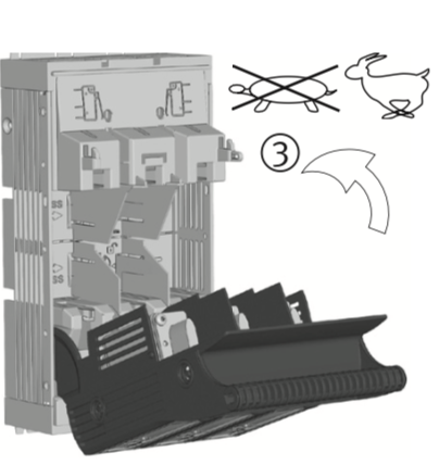
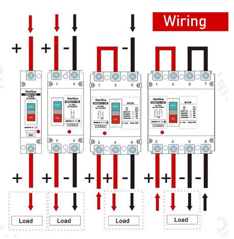
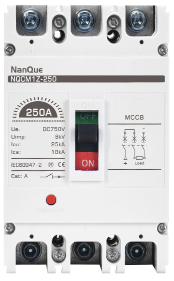
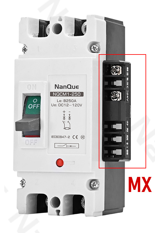
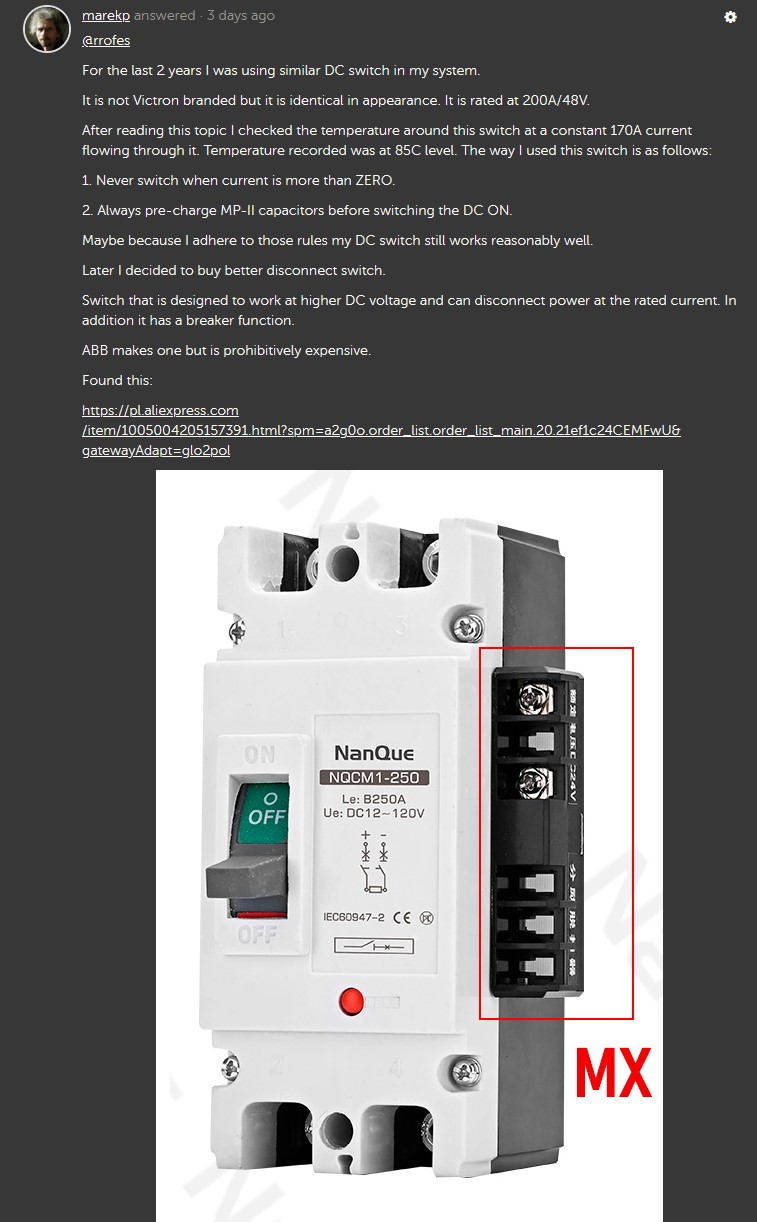
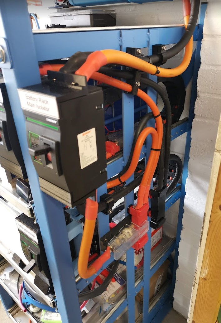
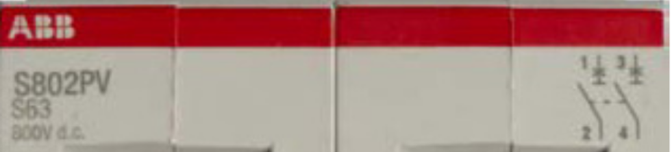
Now look at the symbol on the breaker I suggested:

screen-shot-2023-05-24-at-120109-am.png

They symbolize non-polarized contact design.

Do you have any more questions or concerns?

0 Likes 0 ·
ronski avatar image ronski marekp commented ·

Here is what you posted, as I said it is marked + and - at the top with the load at the bottom, this is the post I replied to, there another post, but I can't see it and need to get ready for work.


marekp.jpg


0 Likes 0 ·
marekp.jpg (148.1 KiB)
daza avatar image daza ronski commented ·

@Ronski @MarekP Guys just put this to bed you are not going to agree on each others point unfortunately this is life. My knowledge of high voltage DC is lacking I’m more AC it’s going to take someone that does DC design for a living.

Guys on another note you don’t think this is thermal transfer from the cables? How thick are they and how long they are? I would be interested to know this as some people have designed no switches one switch or like me both neg and pos

1 Like 1 ·
Show more comments
marekp avatar image marekp ronski commented ·

@Ronski

I know what I posted.

I repeat my question #2.

Do you see any polarization markings on the terminals of the breaker I suggested?

There is no polarization markings on the terminals.

I also, in response to your continued misrepresentation of the breaker, suggested that is non-polarized by stating:

"It is non polarized because DC current can flow from top to bottom as well as from bottom to top".

But you continued with that "polarized" nonsense.

In light of the proof to the contrary do you still claim that is polarized?

Admit that you made mistake and lets finish this nonsensical discussion.

0 Likes 0 ·
marekp avatar image marekp ronski commented ·

@Ronski

You can ignore me if you want but you will not make your posts true by it.

I do not disagree that the polarized breakers have to be used as per instruction.

I am only pointing out, that you completely do not understand the design of the unit I suggested.

Not all "two pole breakers can only be wired for one direction of current flow".

"The three and four way breakers are fine if wired as per manufacturers instructions".

It is so funny because all chanels in 1-pole, 2-pole, 3-pole and 4-pole breakers I suggested are identical in their construction and current can pass through them in both directions.

0 Likes 0 ·
marekp avatar image marekp ronski commented ·

@Ronski

On one hand you say "I didn't rely on salesmen (...)" but on the other you suggest the link to sales pitch of a salesman.

I do not have to research something I know.

You should read specification of the product I suggested and compare it to the one you did.

I repeat, THEY ARE IDENTICAL.

You just do not understand it.

I have to counter what you are pushing here because you are not listening and those other, you are so worried about, have to know that before they make their purchasing/installation decisions.

0 Likes 0 ·
daza avatar image
daza answered ·

Guys can I just ask what cable size are you running, how many batteries and how the batteries are wired prior and after the switches as cable size is an important factor too not just the switch. I will be wiring each pylon to the Lynx distro which would be wired as three separate pylon cables think they are rated 125 amps so each battery a max of pylons 80amps each battery so cable well with in tolerance Lynx 1000amp capable switch 300amp capable and the cable from the switch to the inverter I have no idea but at 120mm square this will be the last thing in the system to heat up long conversation with my supplier over this cable which he is correct less than 5meters 70mm2 and more than 5meters 120mm2 there is no in between i was going for 95mm2 less than 4meter neg and pos combined but according to Victron it’s not spec’ed so I just went OTT with the spec 120mm2 just in case I want more batteries, the place giving the advice does not sell 120mm2, only 70mm2 and 95mm2 some of the other Victron inverters have different rating for the battery cable spec. So I know it was good advice and he wasn’t trying to up sell.

please let me know your system design so we can actually compare Apples to apple

3 comments
2 |3000

Up to 8 attachments (including images) can be used with a maximum of 190.8 MiB each and 286.6 MiB total.

Craig Chamberlain avatar image Craig Chamberlain commented ·
@Daza I’m using two pairs of 2m Pylontech cables, unmodified, into a Lynx Power-In (modified to take fuses like a Distributor). I use 125A fuses for each battery.

I then have a second Lynx Power-In directly attached to the first and this feeds my Multiplus-II 5kVA via a 200A mega fuse, 70mm2 cables and a Victron 275A rotary isolator.

Soon I will be installing a pair of Smart Solar 250/60 MPPTs via 80A fuses into my Power-In via 35mm2 cables. I’ve not decided whether and how to isolate the MPPTs other than on the PV side which will of course have DC disconnects installed.

My general aim is to have the fewest DC connections to minimise voltage drop and heating but without compromising safety.

0 Likes 0 ·
daza avatar image daza Craig Chamberlain commented ·
@Craig Chamberlain how long is the 70mm2 wire could you not have use one power in then to the multi? is it not a bus bar like my distro? Depends how long that 70mm2 is and are you going to add more batteries or are you good?
0 Likes 0 ·
Craig Chamberlain avatar image Craig Chamberlain daza commented ·

My modified Power-In is identical to a Distributor but just without the LEDs and PCB to monitor fuses.

I do intend to add another battery module or two once I have PV up and running because as things stand I won’t get paid for exporting due to it being self installed. So I want enough battery capacity to store everything I generate.

My 70mm2 cables are very short. I think I only bought 1m of red and 1m of black and used about half of each. See attached photo. image.jpg

0 Likes 0 ·
image.jpg (3.1 MiB)
daza avatar image
daza answered ·

Oh they are really short don’t think you will have issues with that. and what is your heat like at the switch @Craig Chamberlain so your overall is just 1 meter 70mm2 yeah your well within cable tolerance be interested to see the other guys who have the heat issue. I’ve clamped my isolation switches on the Lynx to cut down a link cable

2 |3000

Up to 8 attachments (including images) can be used with a maximum of 190.8 MiB each and 286.6 MiB total.

Craig Chamberlain avatar image
Craig Chamberlain answered ·

@Daza Yeah 70mm2 is plenty for my setup. The cable I use is this stuff ( https://www.12voltplanet.co.uk/extra-flexible-tinned-copper-pvc-battery-cable-70mm-485a.html ) and is rated at 485A continuous.

Right now my batteries are charging at 60A and have been for over an hour so I did some voltage drop measurements and temperatures.

First the positive cable route:

  • Inverter +ve to Isolator = 5mV
  • Across Isolator = 23mV
  • Isolator to Power-In (via integral mega fuse) = 24mV
  • Power-In to Bat 1 +ve = 66mV
  • Power-In to Bat 2 +ve = 69mV

And then negative cable route:

  • Inverter -ve to Power-In = 11mV
  • Power-In to Bat 1 = 57mV
  • Power-In to Bat 2 = 59mV

So total voltage drop is 118mV on +ve and 68mV on -ve so 186mV total. That equates to around 11W at 60A so pretty minimal I’d say. Of that, only 1.4W is lost across the isolator.

I measured the temperature of the isolator as best I could and it was around 32C on the +ve cable as it enters and leaves the switch. For reference the -ve cable right next to the switch was 26C. The Pylontech cables are all loosely bundled together until I get time to tidy them up properly but they are only 22C.

Ambient temp is probably not much below this level as it’s an under-stairs cupboard but the air temp varies a lot from ground level to ceiling level.

HTH

Edit: I was going to clamp my isolator to the end of the Power-In bus bar but the bolt on the isolator wasn’t long enough to pass through the bus bar with enough threads to install a locking washer and nut. Also, if I did it this way I’d need to have an external fuse so would be adding in two more connection points (4 if you include the crimps).

12 comments
2 |3000

Up to 8 attachments (including images) can be used with a maximum of 190.8 MiB each and 286.6 MiB total.

daza avatar image daza commented ·

@Craig Chamberlain

You’ve knocked that charging rate right down which would help with the temp and the voltage drops are low which you would expect for cables run that short. So now the question is the positive hotter because of the isolator or because of the current flow? In which case normal.

Would be interested to see how much the resistance goes up per C I’ve been looking through a lot of cable spec and I think these amps are headline figure for 5min durations so think people need to be very careful with the size and length of cable. temperature ie ambient temp also affects its amperage capacity Which in turn increase the heat then it’s just a cycle till one of those cycles break. This is by far the best chart I’ve seen with some deeper spec.

http://centralcables.co.uk/wp-content/uploads/2015/07/Rubber-sheathed-welding-current-ratings.pdf

0 Likes 0 ·
Craig Chamberlain avatar image Craig Chamberlain daza commented ·

I've only reduced the charging rate from the 70A maximum to 60A because I found it reduces the fan noise quite a bit and I've got 5 hours of Octopus Go Faster period and I only need about 3 hours to charge my batteries even at 60A. It's also a bit kinder to the batteries to charge them at the slower rate albeit not necessary.

The positive is undoubtedly hotter due to the presence of more interruptions to the cable (crimps, bolted connections and isolator contacts) because the exact same current is flowing in the positive and negative cables and the cables are adjacent to each other so getting the same ambient temps.

As for resistance variations by temperature, I don't really care much about that because in my opinion if your cables are getting hot to the touch then they are not big enough. I know that PVC can run to at least 70C and other insulation materials can go even higher to 85C or even 105C but there is no way I'd be comfortable with DC cables running beyond the boiling point of water!

The 485A figure I quoted is "nominal" capacity which is for continuous use but depends obviously on ambient temps and whether in conduit, clipped direct, on a cable tray, grouped with other cables etc. I'm probably going to keep my inverter cables clipped direct and separated by at least 1x cable diameter from each other but my battery cables I'll probably be installing in a slotted conduit where there will be some derating required due to grouping but the conduit itself will be freely ventilated. But because I'm using a pair of battery cables per battery, my max continuous battery current will be 80A which is well under the 125A rating of the cables.

So, in my opinion 70mm2 for a Multiplus-II 5kVA is more than adequate to handle the typical 100A continuous discharge rate and 70A charge rate. Even in off grid mode or islanded, it can only reach around 180A discharge at 9000w for a very short time. 70mm2 is also what Victron specify in the installation notes along with a 200A fuse so I think it's best to follow that advice. Personally I would not want to go to 95 or 120mm2 cable because it'll put more stress on the inverter battery lugs during installation and I've seen cases where these have broken off. Getting the 70mm2 lugs on was okay but I tried very hard to ensure I put no stress on the bolts and obviously used a torque wrench to tighten them. My installation is pretty tight between inverter and conduit so that's more of a self inflicted problem to be fair.

0 Likes 0 ·
daza avatar image daza Craig Chamberlain commented ·

The install looks tidy, you are well within the 70mm2 spec length plays a part in that 0m to 5m. The strange thing is Victron don’t even spec the 95mm2 for the multiplus2 48/5000.


cheers for a heads up with the lugs ill put a cable clamp on each. I’ve put my battery cables though a pipe which goes through the conduit so totally isolated from the AC wires. Just been out there labelling up and I should have enough room to get the cables in the inverter, Torquer wrench one of the tools I didn’t have till today lol hopefully I’ll get rid of the cables next month when I can finally get the inverter.

Are your inverter AC input and output 10mm? As I’m herding 16mm can’t fit? But guess I will find out next month lol

They only had black 120mm2 cable so waiting to see where the inverter lands before heat shrinking.


img-3924.jpeg

0 Likes 0 ·
img-3924.jpeg (3.3 MiB)
Craig Chamberlain avatar image Craig Chamberlain daza commented ·
Thanks, yeah it's fairly tidy, especially now with the two Power-In modules, but I still need to do a bit of labelling and final tidying once my solar PV equipment is in place. I'm pretty limited for space and have been working around the DNO board which I didn't really want to disturb. I'll post a better photo of the entire installation once I find some time to tidy things up.


Re the lugs, all I was meaning is to be careful when installing the lugs over the inverter terminal bolts. You don't want to have any bending force on the bolts caused by wrestling a heavy duty cable through a conduit and trying to get it the lug over the end of the bolt.

Yes my AC cables are all 10mm. I did consider going for 16mm and I think the MP2 can take 16mm cables even though it says 13mm or some strange size as the limit. But, honestly, again given how short the cables are, and the fact they are behind a 50A MCB, they should be absolutely fine. Yes I know that technically Power Assist can boost the grid power by 20A or so, but my grid limit is 100A and I never get anywhere close to that. Even right now with the EV charging and my ESS batteries charging, and the dishwasher and washing machine running, the peak load was just 64.6A.

I hope your installation goes smoothly - when are you expecting delivery?

0 Likes 0 ·
daza avatar image daza Craig Chamberlain commented ·
Yeah I’ve looked on a conversion chart for the cable and it says 6awg is equivalent to 16mm2 so I changed my output as I want the full 63amps that the MCB can give.


I’ve used my isolators to convert my cable sizes from 10mm it goes to 16mm in the CU then the 16mm AC out goes to 25mm. The 10mm AC out was just tripping my OCD.


Ah ok I think the garage is going to be blue with words when installing the 120mm as a lot of people are saying good luck lol. Not ordered yet can only move on it on payday hence why my install is taking sooooooo long, thanks I’ll post up when I get further.
0 Likes 0 ·
Craig Chamberlain avatar image Craig Chamberlain daza commented ·

Maybe I'm misunderstanding you about the 63A but page 14 of the MP2 manual says:

The AC input must be protected by a fuse or magnetic circuit breaker rated at 32 A (for 3 kVA model), 50 A (for 5 kVA model) and 100 A (for 8 kVA and 10 kVA model) or less, and cable cross-section must be sized accordingly.

So you should be using a 50A MCB not a 63A one. Even at 63A, that's fine for 10mm2 cable clipped direct but at 50A it's well within spec. Nothing wrong with increasing cable size as long as it fits the terminals though. I just much prefer working with 10mm compared to 16 or 25mm, and can create neater connections with the 10mm.

If you're worried about installing the 120mm2 then you can easily just order some 70mm2 as per Victron's spec and just use that. You'll certainly utter a few profanities if you snap off the inverter battery connection bolts, or if the lugs are just too big to fit the space. The OceanFlex cable from 12vplanet is really nice wire and comes in red and black. Not cheap at £27/meter but that just encourages you to keep cable runs short! :)

0 Likes 0 ·
daza avatar image daza Craig Chamberlain commented ·

@Craig Chamberlain yeah with the power assist ac out1 goes to 71.something amps. 63 amps is the nearest rated fuse to that, AC input is indeed 50 amps that’s why I’ve just used 10mm on that side. Lol 120mm2 is not cheap and not a lot of places looking to do it in 2 meter lengths. 10mm is easier to route and bend but just not comfortable with the power assist 71amps. even though the clamp meter says I’m using 40 something amps but thinking of a couple of heaters so that figure is going to go up.

0 Likes 0 ·
Craig Chamberlain avatar image Craig Chamberlain daza commented ·
Yeah, in theory PowerAssist can boost to 71A but in practice, in an ESS configuration it's pretty unlikely, and with the 10mm2 cables being so short, it would take an extended period at 71A to even warm them up.


And if you're protecting the cables with a 63A fuse then 10mm2 is perfectly fine in any case. If you were stepping up to the next fuse size (80A?) then for sure I'd go with 16mm cable.

Looking at VRM for the last 7 days, the highest current on my AC Out 1 connection was around 4800w which is when we do the evening dishwasher and washing machine at the start of the Octopus Go period (21:30hrs). But that coincides with our ESS scheduled charge window as well so PowerAssist would not kick in while the batteries were being charged.

0 Likes 0 ·
daza avatar image daza Craig Chamberlain commented ·
Yeah the boys did say it would be ok but I like to over spec, re the 80amp no real point as I’ve shedded the washing machine and dryer from that load and if and when I get an EV charger I have provided it to go on the sheaded load side. Plus it would have to be a RCD don’t really want it tripped, only in an overload situation if that makes sense. 63amp overload works well as the butchers from the DNO came to replace the 60amp for 100amp and just flicked on the whole CU without loading it up.
0 Likes 0 ·
Craig Chamberlain avatar image Craig Chamberlain daza commented ·
Interesting - we still have all three of our ring final circuits (upstairs, downstairs, kitchen/utility) on the maintained loads CU (via AC Out-1) but certainly we do always try to only run the washing machine or drier during the off-peak period. The only loads that don't go through AC-Out1 for us are our rangemaster cooker, electric shower and garage sub-main which powers the EV charger. The cooker has a theoretical max draw of 64A but is on a 40A RCBO (diversity etc), the shower is 9.5kW on a 40A RCBO, and the garage is on a 40A MCB with type A RCDs in the garage CU for the EV and other loads. There didn't seem much point in running these loads through AC-Out1 as we wouldn't use them in a grid loss situation.


But everything else is fed via AC-Out1 including the already mentioned ring final circuits, all lighting circuits, boiler, alarms/smokes. The only wrinkle in our setup is that the chest freezer out in the garage is fed from the garage sub-main and so is not maintained in a grid loss situation. But assuming we were home when it happened, we'd just run an extension cable out there from the house. Maybe I'll pull a 2.5mm SWA from house to garage through my underground duct to provide a maintained feed purely for the freezer. Would be nice for peace of mind.

1 Like 1 ·
daza avatar image daza Craig Chamberlain commented ·

My house only ever had two rings the kitchen and the rest of the house so annoying the boys said it was better as radials so every circuit bar the kitchen was turned into a radial. Diversity I got fed up doing the calculations as it was over 100amp on a 60amp fuse lol didn’t make sense I put a clamp on loaded it up and it was 40 something amps with the washing machine and tumble dryer.


Forgot the washing machine and the dryer in the garage are on a ring socket of there own the rest in there are radial on crit load. Wish I done the conduit now as I think I’m going to get another ET112 to see the solar in the Victron setup

0 Likes 0 ·
Craig Chamberlain avatar image Craig Chamberlain commented ·
Just a follow up on my temperature measurements above, I just did another measurement during an Octopus Energy "Saving Session" where I was doing a maximal forced discharge for 90 mins. To my surprise, the temperature at the inverter isolator switch was over 70C... Too hot IMHO. This was measured using an infra red temperature gun on the output side lug. The negative cable which was right next to it but obviously not going through a switch was at 32C and ambient temp was 28C. The measurement was taken 60 mins into the 90 min event.


This was very much a stress test with the inverter set to maximum export grid set point for the full 90 mins, but the inverter current was still just over 100A and for a switch supposedly rated at 275A continuous, this is very poor. I will be investigating further at the weekend and will be checking connection torque and probably disassembling the switch to look for any signs of deterioration internally. Right now I'm drawing 40A DC through the inverter and it's running at around 40C which is okay I guess but 70C at 100A seems too hot to me. Hopefully I can improve this with a bit of contact polishing internally and retorquing the fasteners otherwise I'll be looking for a better switch.
0 Likes 0 ·
ronski avatar image
ronski answered ·

I just found this thread after measuring the temperature of the connections to my isolator, they were just under 40c with 140A passing through, but I see thats perfectly normal. Thats 40 x 8 copper busbar modified to fit, used M10 half nuts with a locking plate, and thread lock.

Cables are mostly 70mm2, but main ones from rack busbar to Lynx Smart shunt are 120mm2.

Isolator has never been switched under load, system has precharge, and is also grid tied.

back-of-isolator.jpg


negative-cable-adapter-cover.jpg


inverter-wired-in.jpg

rack-busbar-1.jpg

lynx-terminal-cover.jpg


2 |3000

Up to 8 attachments (including images) can be used with a maximum of 190.8 MiB each and 286.6 MiB total.

daza avatar image
daza answered ·

@Craig Chamberlain i see what you mean about the battery terminals but a modification to slim it down as they were too small wide and increased the eyelets slighty so it ribs the threads when installing as you can’t install the terun also square but easy enough. As @MarekP suggested I’ve installed a pre-charge button now. I also put temperature sensors on the Neg And Pos isolation switches also wired in a MK3 USB so I don’t have to drop the multiplus2 shroud orange Ethernet cable is the new edition.


img-3986.jpeg


img-3986.jpeg (3.0 MiB)
2 comments
2 |3000

Up to 8 attachments (including images) can be used with a maximum of 190.8 MiB each and 286.6 MiB total.

Craig Chamberlain avatar image Craig Chamberlain commented ·
Hi @daza as I'm sure you are aware, it's crucial to have the lugs sitting absolutely flush with the multiplus terminals so make sure you remove any burrs after your modification.


I'd suggest chamfering the edges of the lugs where you made the cuts with a file and use a large drill bit (eg. 12mm+) just twisting gently by hand to chamfer the edges around the bolt holes. If you don't get the lugs sitting flush then you'll easily undo any benefit of the larger size.


Once in service and under decent load, measure voltage drops across all joints to make sure you don't have a high resistance connection.
0 Likes 0 ·
daza avatar image daza Craig Chamberlain commented ·

Thanks mate yeah all good as I used my cone cutter, it was only because you couldn’t actually get them square and these terminals didn’t even fit though the wholes without modification.


img-3984.jpeg

0 Likes 0 ·
img-3984.jpeg (2.1 MiB)
becker avatar image
becker answered ·

Hi, I noticed that my Switch gets hot at 50-60A (barely touchable).

I mesured 45mV @55A.

today I disassembled it:

1.jpg

2.jpg


I´ll call the dealer.


1.jpg (579.7 KiB)
2.jpg (508.1 KiB)
2 comments
2 |3000

Up to 8 attachments (including images) can be used with a maximum of 190.8 MiB each and 286.6 MiB total.

Craig Chamberlain avatar image Craig Chamberlain commented ·
How confident are you that this was a genuine Victron switch and not a third party copy? You mention calling the dealer - can I assume that is who supplied it?

As you may already be aware, the thing that can cause this is the surge you get when initially powering up the inverter or if it has been powered down long enough for the onboard capacitors to discharge. That can cause an arc which will contaminate the contacts with carbonised particles which will increase the resistance which in turn will cause overheating. Ideally you need some sort of soft start circuit if your battery modules don't have one built into the BMS.

Unfortunately I think your switch is beyond repair so hopefully you can get a new one quite quickly.

2 Likes 2 ·
daza avatar image daza commented ·
Yeah I can kinda see why, I’m guessing this isn’t even conducive lubrican/Grease, I’ll open the one I’m not using as I deleted the switch on the neg post. I may have to look at the switch @MarekP posted
0 Likes 0 ·
Dušan Klofutar avatar image
Dušan Klofutar answered ·

Hi!

In my off grid setup with 1800Ah lead acid battery bank and Multiplus 12/3000/120-16, i never in four years have any temperature problems on any contacts on high loads.My inverter is connected with 2X50mm2 Cu wires, switch is Cermag 250A, big and sturdy.

screenshot-20231130-181231-chrome.jpg


2 |3000

Up to 8 attachments (including images) can be used with a maximum of 190.8 MiB each and 286.6 MiB total.

Related Resources

Additional resources still need to be added for this topic