I read these posts:
But I could not get it working. Here is what worked for me. I will try to be as comprehensive as possible as most guides and posts miss out many steps, thereby confusing those who are not so familiar with these devices.
If you are adding this modification to an existing system, please turn your inverter off or at least switch it to not being in inverter mode, whilst you make these changes, they will require resetting your BMS a few times.
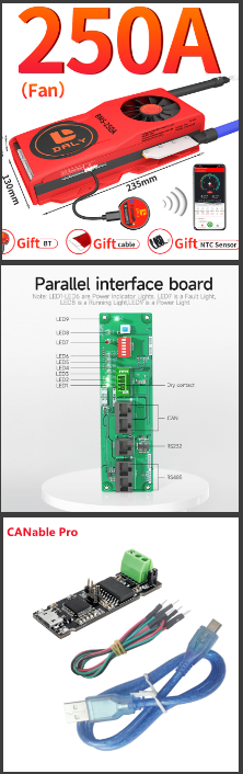
1. Daly BMS - I am using one of the bigger units. I have the 250amp 16S aimed at LiFePO4 cells.
I believe the smaller units do not always have the full suite of communications including rs485 and CAN as well as UART. When buying the BMS enquire about the comms and ensure you get one with all the comms. If you plug in your interface board and it doesn't light up, your BMS doesn't have advanced comms.
Firmware seems to matter. Load pc master and go to "read parameters" tab and hit read. It's on the mid left side saying SW version. I have tried 4 BMS units so far and the ones that work with this technique seem to have firmware ending in xxxx100T. I have tried units with firmware ending xxxLED which didn't work.
More on this later, but whilst pc master can write firmware, firmware isn't available widely. Daly don't give it out apparently. Will ask them.
You can still use UART to Bluetooth or UART to USB for monitoring but you won't be able to connect to Victron using this guide.
I tried it on a 100 amp 4S BMS and it did not work.
2. Interface board also called WNT board.
I ordered this from Daly Smart Store on Aliexpress, although you could also order from Daly Official Store too (and others). When ordering I specified to them by message, that I needed to connect Victron via CAN when they asked me. I believe this is important, don't skip this.
This unit comes with an rj45 to rs485 adaptor cable which you will need.
3. Since I am using Venus OS on Raspberry Pi and not a VenusGX or CerboGX or Multiplus GX unit, I also needed a CAN interface for my Raspberry Pi.
There is a unit called a Canable which was out of stock from its original creator. So sadly I had to buy a copied unit from China. Sadly, as I invented a 3D printer sensor some years ago and the Chinese copied almost straightaway and were selling it on Aliexpress. Karma I guess.
The Canable unit plugs into the RPI via USB. However, I was told that you have to flash it to new firmware called Candlelight to make it work.
The guide to flashing it is here:
https://canable.io/getting-started.html#alt-firmware
You follow that page to the following page
https://canable.io/updater/canable1.html
Where after you set the "boot" jumper on the Canable - you can flash it from the webpage to "candlelight (a8a0757)".
Also download Cangaroo for PC, which is a can monitoring software for testing:
https://canable.io/utilities/cangaroo-win32-ccdcb64.zip
Once you have done this you can connect the Canable to a PC to test the CAN connection.
4. PC. Any small NUC or old laptop running windows 10/11 will work fine.
Download the latest version of PCMaster the windows software for DalyBMS here:
Unzip this somewhere and make a shortcut to PCmaster.
Unzip and create a shortcut for Cangaroo too.
5. Connect your BMS to the interface board/WNT using the supplied cable, it plugs into the port between the UART and Temp sensor ports. Carefully, make sure the plug is firmly inserted, they don't always go in easily.
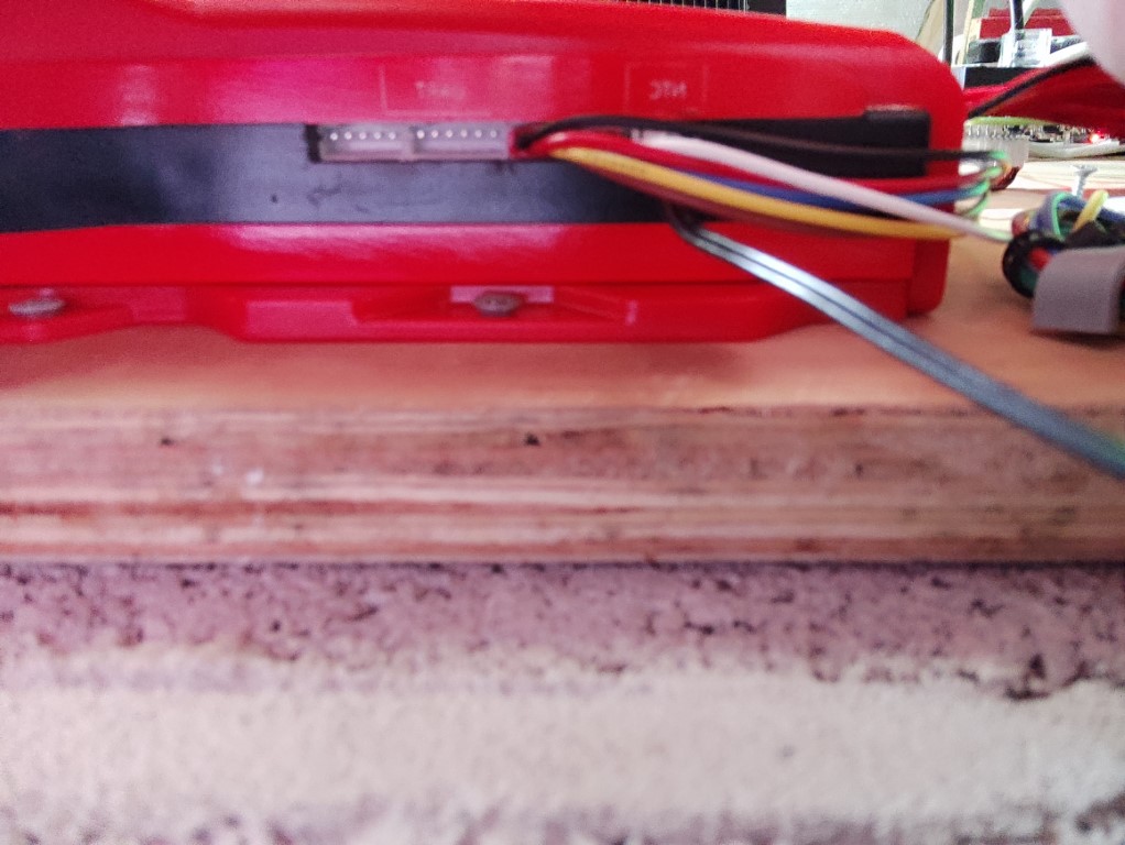
I disconnected the interface I was using which was plugged into the UART port. I don't know if you have to - but it was not working when both were connected. 
At this stage, I reset my BMS by turning off my battery master switch and also pulling out and re-inserting the balancing cable plug.
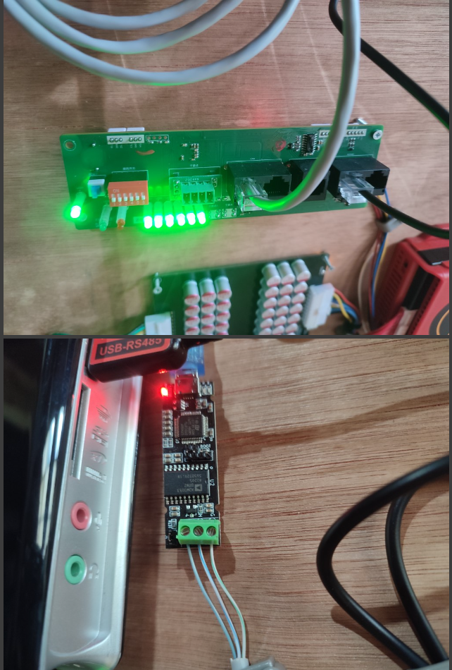
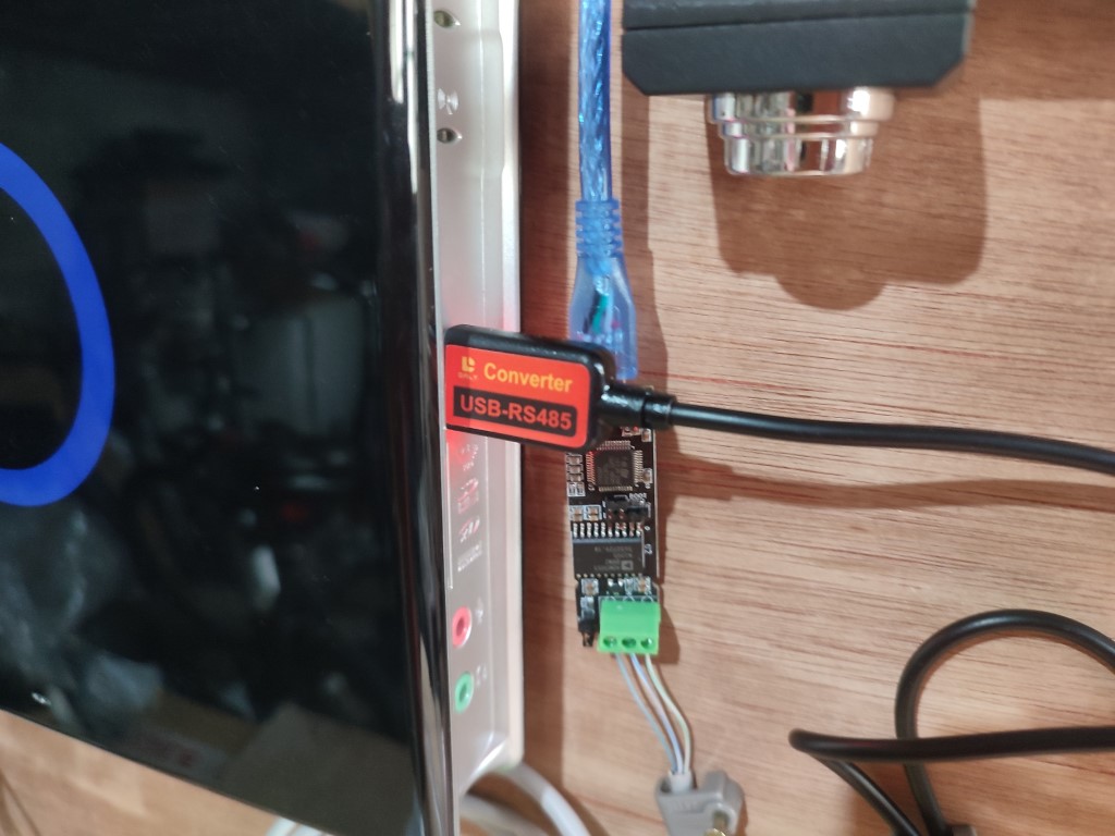
6. Attach the RS485 cable supplied with the interface board to one of the two RS485 RJ45 ports and the other end to the PC USB port.
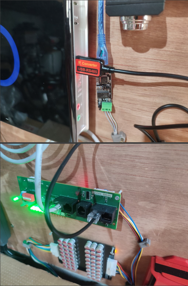
The PC will show in "device manager" a USB COM port, it will give it a number, mine was COM3.
Now open the PCmaster2.17 software.
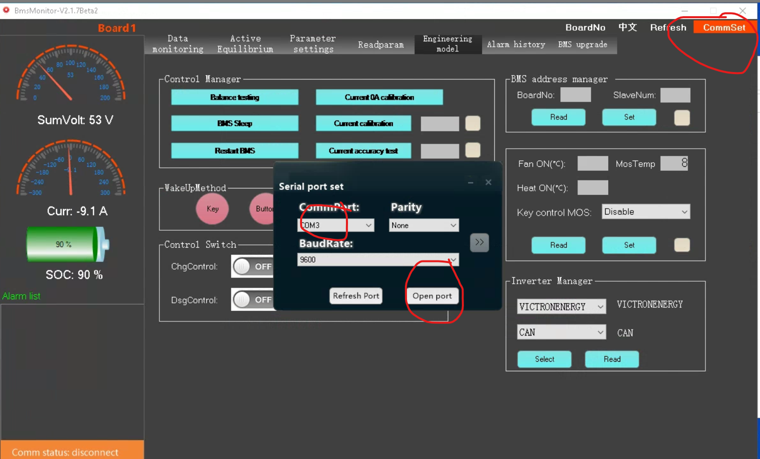
Hit CommSet - choose your com port and hit open port. Connection will fill the first tab "data monitoring with your battery voltages" If this doesn't connect, reboot the PC and try again, this always works for me in the event of no RS485 connection.
You can now see the data from your BMS and you can change any settings you need to.
I will not cover setting up your BMS for your battery chemistry and series etc. This assumes you have a working battery and BMS configured for it correctly.
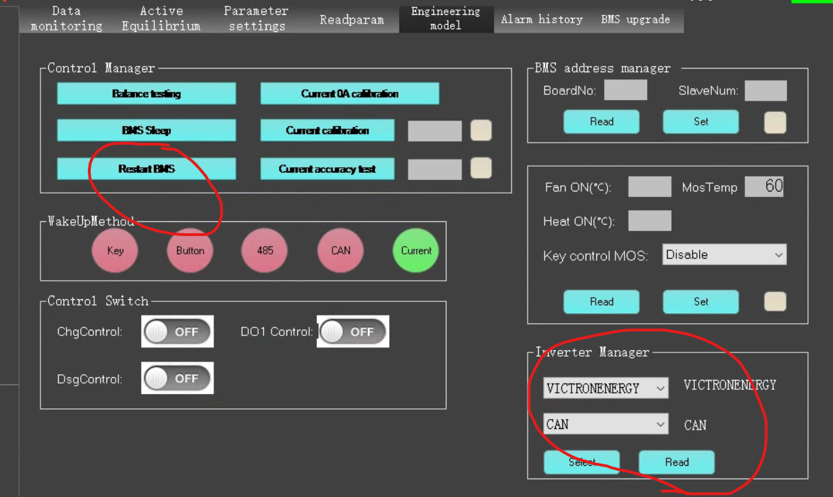
I set VictronEnergy and CAN in the bottom right box in the "engineering model" tab. Then reset the BMS.
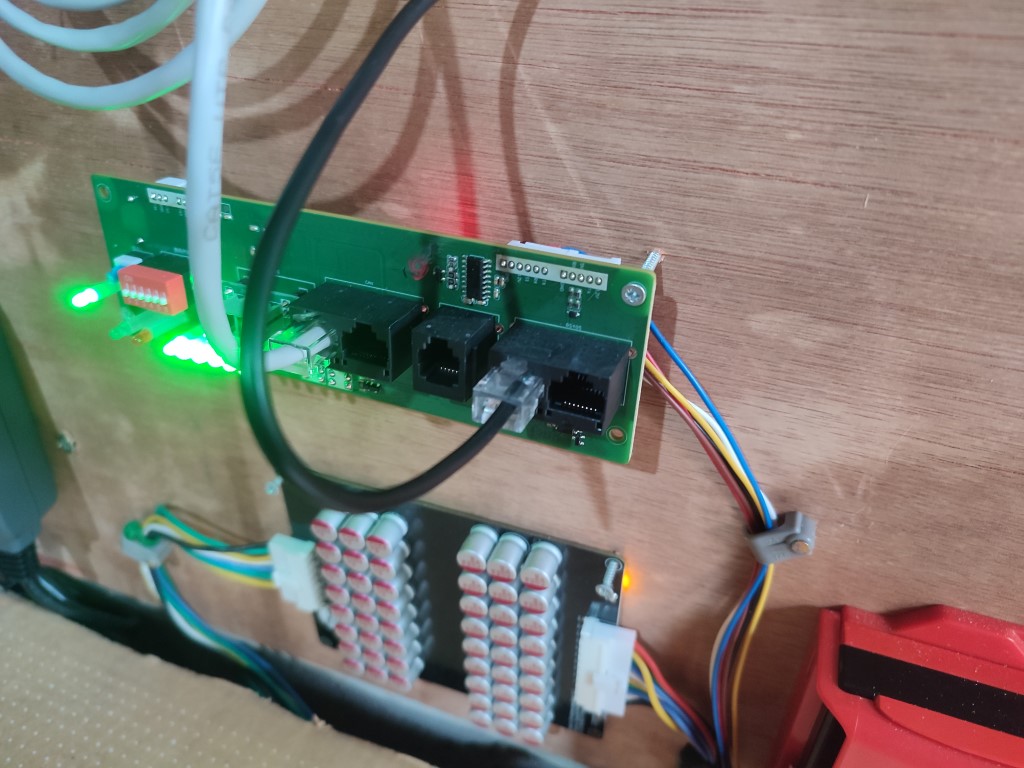
7. CAN cable. To attach the CAN to the interface board you need to make or adapt a network cable. Test the cable before use with a multimeter. Set it up like this (thanks to panicman for the image below):
 Pin 3 - usually green & white - goes to the Canable G connector (or pin 3 on VEcan)
Pin 4 usually solid blue - goes to the Canable CAN-L connector (or pin 8 on VEcan)
Pin 5 usually blue & white goes to the Canable CAN-H connector (or pin 7 on VEcan)
Showing connection from interface board to Canable - Canable connectors go L, H, GND from left to right (so pin 3, pin 5, pin 4 on the interface board side left to right). The Canable has a little jumper next to the connectors for a built-in 120ohm terminator. Leave it connected, it seems to work fine with this jumper connected.
Please note, the red bank of dip switches on the interface board are for identification. Some posts say they must all be down for this to work, so I put them all down. I think if you have more than one interface board, you can give the second one a different ID by setting a different DIP switch config, but don't quote me on it.
8. Test the connection.
At this point, I have the Canable attached to the PC. I ran Cangaroo. Hit "start measurement" and selected my Canable as the interface.
You might need to restart the BMS using PCmaster as in step 6 if you don't see any CAN data or check all steps and connections.
If all is working you will see CAN data on the screen which is a bunch of numbers in hexidecimal.
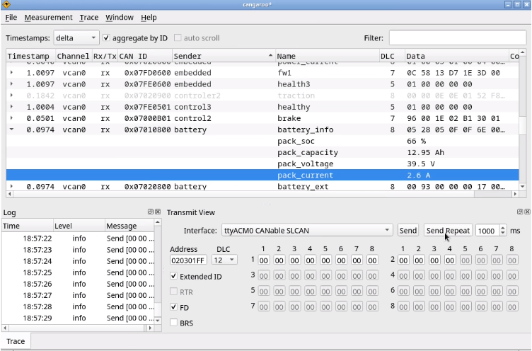 This is not a screenshot from DalyBMS, there is less data but you get the idea, the window will not be empty.
This has verified that the DalyBMS is sending CAN data. Well done, you're nearly there.
9. Disconnect the Canable from the PC and plug it into a spare USB port on the Raspberry Pi.
If you are not using RPI, plug in your CAN cable into your Cerbo/Venus/GX device VEcan port.
In theory, the RPI should not require rebooting, but if it doesn't work reboot it.
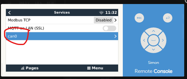
You will see in the remote console under "services" a Linux standard CAN interface which is automatically available on the latest versions of VenusOS 2.90 onwards I think.
If you cannot see the can0 interface check everything or update your VenusOS to the latest version here https://updates.victronenergy.com/feeds/venus/release/images/raspberrypi2/
 Entering that menu shows:
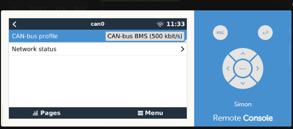
Make sure that "CAN-bus BMS (500 kbit/s)" is selected.
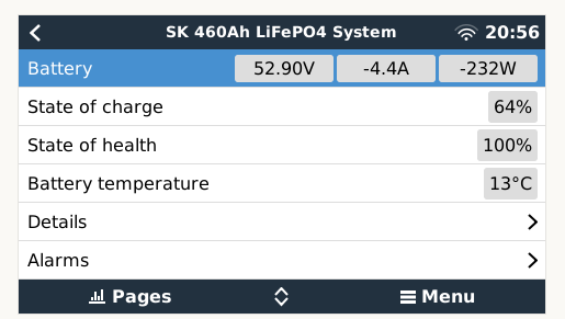
In your remote console main menu you should now see the BMS:
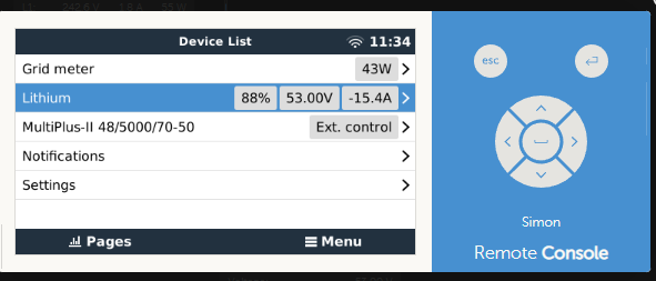
Showing as "Lithium".
You may immediately get a low battery warning: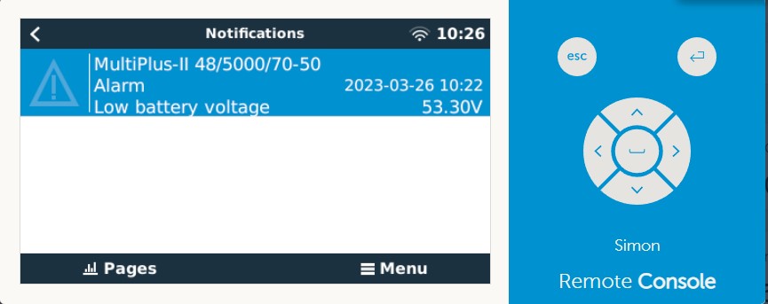
This is because the Multiplus II has had its battery monitor changed, and it needs a reset.
I reset the inverter from the "multiplus-II 48/5000/70-50" menu "advanced" - "system reset"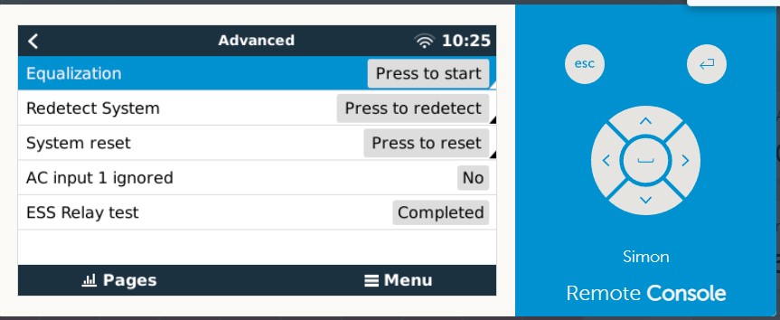
At that stage, normal operation resumed. I am using my system as a grid parallel ESS and so the status for the inverter changed to "ext. control". I presume this is because it isn't using its internal battery monitor anymore.
At this stage things are working, my system is now using the BMS as the battery monitor and SoC is determined by the BMS which should track much better than when I was using the Multiplus II as the battery monitor. I will report back any quirks or issues below.
The current does jump about more than it did when I was using the Multiplus' built-in battery monitor. It is possible to calibrate the current on the DalyBMS using the PCmaster software but I have not yet figured out how to.
I hope this guide is helpful. I have not got a "proper" GX device so I have not actually tested this guide when used to connect a Daly BMS to a VEcan port but I presume that it is basically the same without the Canable interface being involved.
Please post any comments/suggestions/your experience below.