question

romarub avatar image
romarub asked

Imbalance when running two MultiPlus-IIs in parallel

Hello colleagues! I need your help. I will be glad if the Victron staff can answer me, as this is important and now it is urgent. I also hope that the information below will be useful to other installers. I have installed dozens of Victron Energy systems, including three-phase (with three units) and single-phase (with one and two units), and they all work very well. Until 2022, I did not encounter the need to add parallel blocks to an already existing system.

Last year, I needed to add a second inverter to one already running in a single-phase system. Both inverters were of the same modification: MultiPlus-II 48/5000, had the same "product ID" 2623 and the same "PN" PMP482505010. The only difference between the inverters was that one of them was bought two years earlier than the other.

Of course, I carefully studied these official documents from Victron:

Parallel, split- and three-phase VE.Bus systems

VE.Bus firmware versions explained

Theory on wiring systems

Wiring Unlimited

The official documentation says: "All units in one system must be the same type and firmware version, this includes the same size, system voltage, and feature set. The type is indicated by the first four digits of the firmware version number."

It also says "For units in parallel: Both the DC and AC wiring needs to be symmetrical per phase: use the same length, type and cross-section to every unit in the phase. To make this easy, use a bus-bar or power-post before and after the inverter/chargers. Also, apply the same torque on all connections." ... and so on.

But as practice has shown, all this is not enough, and if "same type" blocks have different hardware revisions, then they may not work smoothly when connected in parallel. But this is not mentioned in the documentation.

Before adding the second inverter, I updated the firmware of both inverters to the latest version 496 at that time, and then configured them for parallel operation with identical settings. The AC and DC cables between the busbars and each inverter had exactly the same length, type and cross section (6 mm² for AC and 70 mm² for DC). The fuses were exactly the same for each block, and all terminals were tightened with the same torque. And despite all this, the old inverter was loaded more than the new one.

At full load the difference is about 10%, at light load it is about 300%. This resulted in the cooling fan running on only one inverter at medium loads, and when approaching maximum load, the "Overload" LED also flashes on only one inverter. As a result, it is impossible to get the maximum power of both inverters, since one of them will be overloaded earlier and turn off the entire system. I am attaching a screenshot with several current measurements at various loads. All measurements were taken with the external grid switched off, the MPPT chargers and the Fronius inverter were also switched off. I just turned on and off various loads and recorded the readings. The system was controlled by an Octo GX running the then latest version of Venus OS 2.87.

00873-imbalance.png

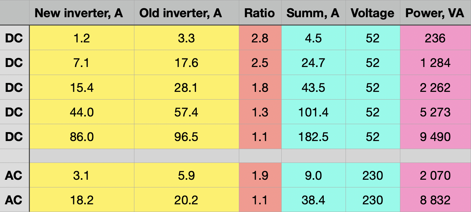
After fixing the results, I did some experiments, changing the length of the cables on the AC side to balance the load of the inverters, but it did not help. Even when I increased the length of the cables on one inverter several times over the other, it had very little effect on the load ratio between the inverters. For example, if at the same cable length at a certain load the ratio was 1.8, then when the cable length was doubled for a more loaded inverter and the same load, the ratio "improved" only up to 1.6. Even a tenfold increase in length for a more loaded inverter did not allow me to compensate for this imbalance. I changed the blocks in places, it did not help either. I carried out a similar experiment on the DC side, without getting the desired result. I even did additional tests without fuses on the AC and DC side to rule out their influence.

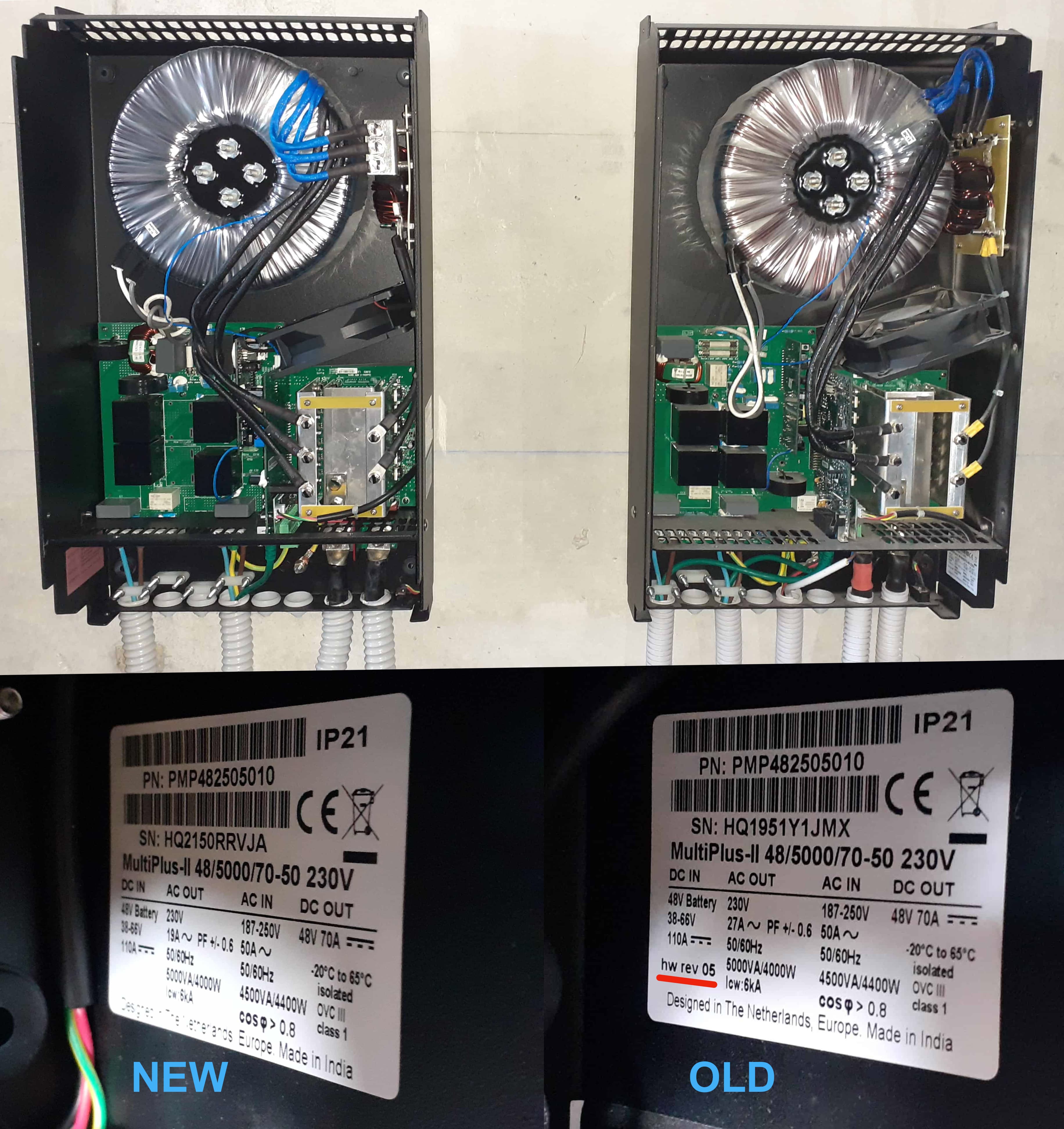
Having removed the front covers of the inverters, I found that their internal structure has many differences, that is, they are definitely different hardware revisions. At the same time, the hardware revision (05) was indicated on the old inverter, but it was not indicated on the new one (I am attaching a photo).

00873-imbalance.jpg

After researching similar situations in the Victron community, I found that other installers are also facing a similar problem.

Here is one of the most detailed situations where the user @MarekP was able to solve the problem only after replacing one of the blocks with a block with identical hardware revisions:

How to balance 2 MP-IIs in parallel

I ended up not being able to solve the problem at the time, and the customer was somewhat dissatisfied as he couldn't get full power from the two inverters.


But now I have a similar situation. A few months ago we installed one EasySolar-II 3000 (SN: HQ2230TPXDW, PN: PMP482307010) for our client. Now this customer has asked for a MultiPlus-II 3000 to be added in parallel to double the power. Two options are currently available in E-order: PMP482305010 and PMP482305012 (as far as I know, they are identical, but are produced in two different factories due to high demand). I'm afraid to face the same problem if the revisions of the already working EasySolar-II 3000 and the new MultiPlus-II 3000 are different. At the same time, I can't find information anywhere on how to check the revision number by the serial number of an existing inverter, and how to find out the revision number of new inverters available in E-order before buying. Does anyone know this?

If they have different revisions, then it's better for us not to risk it and buy a more powerful EasySolar-II 5000 instead of the already working EasySolar-II 3000. Of course, then we will have a new problem - to sell someone the already used EasySolar-II 3000 with a loss of value, but at least our client will be happy with the result.


To summarize, I have two questions:

1. What should I do with the first system I couldn't balance last year? The client resigned himself to this state of affairs, but it cannot be said that he was satisfied. I would like to somehow correct this situation.

2. What should be done in the future in such situations, when it is necessary to add an additional inverter to an already operating system? How to check block revisions in advance?

Thank you!

multiplus in parallel
00873-imbalance.jpg (900.5 KiB)
00873-imbalance.png (425.5 KiB)
2 |3000

Up to 8 attachments (including images) can be used with a maximum of 190.8 MiB each and 286.6 MiB total.

8 Answers
Alexandra avatar image
Alexandra answered ·

@RomaRub

Even if you do have two inverters from exactly the same batch, if one was used and one stayed boxed their values would be different. When capacitors and other electronic components are used/cycled/heated their values change over time.

Imbalances are to be expected as well, and it is made worse by cabling and resistance differences both on AC and DC.

It can be "tuned" a bit by trimming some wiring and changing the cable resistance that way on a parallel system to try balance loads. ( @Paulcupine mentioned this as a factor - correct voltage amps and resistance have a close relationship)

The key to balancing is always the resistance; internal in the inverter and external in wiring. This is where the engineering part of electrical engineering comes in.

3 comments
2 |3000

Up to 8 attachments (including images) can be used with a maximum of 190.8 MiB each and 286.6 MiB total.

paulcupine avatar image paulcupine commented ·
Thanks @Alexandra , I think you have made up my mind. Continuing down the path of fiddling with wiring lengths is going to lead to further frustration. I should probably just get a new 8000 or 10000 and sell my two 3000s on. It's not where I wanted to be spending right now, but hey.
0 Likes 0 ·
Alexandra avatar image Alexandra ♦ paulcupine commented ·
@Paulcupine

Yeah. It is always better to go with one unit. Less self consumption power and efficiency is way higher.

0 Likes 0 ·
paulcupine avatar image paulcupine commented ·
Further info from Victron themselves is that there is no difference in internal resistance between the different hardware revisions of the MPii as such, but that an older unit most likely has relays that aren't contacting as well as a new one, resulting in higher resistance due to age/use rather than design/implementation.
0 Likes 0 ·
romarub avatar image
romarub answered ·

Thanks a lot to everyone for the answers, especially @Alexandra, who noted that even blocks with the same hardware revision, one of which worked and the other was in the box, may have different internal resistance, which will lead to imbalance. I hope that this imbalance will be less than with different hardware revisions, in the end @MarekP was able to solve the problem by changing the block to another one with an identical hardware revision. However, I see a general consensus that it is best to avoid adding parallel blocks to an already running system. Perhaps we will not take risks and replace our client's EasySolar-II 3000 with a more powerful EasySolar-II 5000. It is a pity that it is impossible to somehow officially check the hardware revision number.

2 |3000

Up to 8 attachments (including images) can be used with a maximum of 190.8 MiB each and 286.6 MiB total.

marekp avatar image
marekp answered ·

@RomaRub

@Paulcupine

In relation to the HW Revision I found this info:

Determining used hardware version

There has been a change (late 2020/early 2021) in the way the Ground relay test mechanism works. Newer units use an auxiliary contact on the ground relay, while older units measure the voltage between GND and Neutral.

The advantage of the new version is that the checking of the ground relay is immune to how the system is wired, and any possible errors in wiring on the input side and/or the output of the inverter/charger.

How to diagnose an error strongly depends on the underlying hardware, therefore as a first step, find out which hardware version is used, by using this table:

Model Serial number
MultiPlus-II 48V 3kVA ≤ HQ2048
MultiPlus-II 48V 3kVA GX ≤ HQ2050
MultiPlus-II 24V 3kVA ≤ HQ2101
MultiPlus-II 48V 5kVA ≤ HQ2116
MultiPlus-II 48V 5kVA GX ≤ HQ2122
EasySolar-II 48V 3kVA MPPT 250-70 GX ≤ HQ2130
All other models Any serial number


https://www.victronenergy.com/live/ve.bus:ve.bus_error_codes

2 |3000

Up to 8 attachments (including images) can be used with a maximum of 190.8 MiB each and 286.6 MiB total.

paulcupine avatar image
paulcupine answered ·

I have two Multiplus II 3000s with different hardware revisions (bought about 2 years apart) and have also had issues with balancing them. The symptoms are sometimes non-obvious, like the GX device constraining the output of attached Fronius grid tie inverters when the battery is not full.

My theory is that the different hardware revisions have different internal resistances, so having exactly matching cabling (as required by Victron), results in different resistances seen by the inverters in the parallel set. Since the master does the measuring and then communicates some value to the other inverter(s), the other inverter(s) produce too much or too little power compared to the master due to the difference in real resistance (of both cabling and internal to the inverter).

If, for example, the slave inverters produce too much output, the GX device responds by reducing the output of the grid tie inverter first before increasing charging (or decreasing discharging) of the Multi's. I'm not sure why it does this if the battery is not full, but perhaps someone at Victron can explain. When the system is balanced, the Multi's charging and the Fronius output is increased and things run ok.

Any sort of imbalance seems to make the reaction to the loads going on and coming off quite unstable and the PV production ends up in a downward spiral.

I had this issue with a Fronius Galvo (on ACout) when I first installed my two Multi's in parallel. I managed to get it working by reducing the length of the ACin cabling to the one inverter. I have now introduced a second Fronius (this one on ACin) and am sitting with a similar problem again. Today I will try severely downgrading the ACin cabling from short runs of 2.5mm2 to long runs of 1mm2.

I'm almost at the point of selling these two Multi's and getting a single larger one, but with the power crisis in South Africa at the moment, I would prefer to be spending money on more PV generation than on replacing existing inverters.


2 |3000

Up to 8 attachments (including images) can be used with a maximum of 190.8 MiB each and 286.6 MiB total.

nickdb avatar image
nickdb answered ·

The different powerpacks can cause this so if you mix serial numbers before/after the change then this is to be expected.

If you discuss with your distributor, you may be able to RMA the older unit. I am not sure what the age cutoffs are for this.

Always make the newest serial number master in a parallel set, so make sure you did that as well.

6 comments
2 |3000

Up to 8 attachments (including images) can be used with a maximum of 190.8 MiB each and 286.6 MiB total.

paulcupine avatar image paulcupine commented ·

"Always make the newest serial number master in a parallel set, so make sure you did that as well. "

I have not done this. What is the reason for this preference?

Also, when did the power packs change? At what hardware revision? Is this info available somewhere from an official source?

0 Likes 0 ·
nickdb avatar image nickdb ♦♦ paulcupine commented ·
It is always good practice to have new systems as master, it is common practice for batteries as well, and in parallel systems I have found it to be helpful.

The change was from HQ2116 in the 5k's

0 Likes 0 ·
paulcupine avatar image paulcupine nickdb ♦♦ commented ·
Thanks, I have 3k units. One is an HQ2009 and the other an HQ2150. I now have the option of getting a used HQ2119. Can I expect the HQ2119 to work with the HQ2150? Do you know what the change value was in the 3k units?
0 Likes 0 ·
nickdb avatar image nickdb ♦♦ paulcupine commented ·
I would have to go find out. Simplest option is pop the cover, there is a distinct difference between the two.
0 Likes 0 ·
paulcupine avatar image paulcupine nickdb ♦♦ commented ·
I do not have pop-the-cover access to the unit I have not (yet) bought, so a definitive answer based on the serial number would be first prize.
0 Likes 0 ·
marekp avatar image marekp paulcupine commented ·

@Paulcupine

I do not now if this will help you decide but, I have the following MP-II-48/3000 part numbers and they work i parallel setup without the problems.

HQ2049
HQ2110

0 Likes 0 ·
iand avatar image
iand answered ·

Is that correct (one bigger one is more efficient and lower power), or only for some models?

Because there is no Quattro II 48/10000 yet, I'm looking at using 2 parallel Quattro II 48/5000 (96%, 2x18W=36W zero-load, EUR4750) compared to a Multiplus II 48/10000 (96%, 38W zero-load) with an external ATS (total EUR4480) -- a bit cheaper but much more of a PITA to integrate.

2 |3000

Up to 8 attachments (including images) can be used with a maximum of 190.8 MiB each and 286.6 MiB total.

macoscar avatar image
macoscar answered ·

Unfortunately, I have a similar problem with a parallel system. I bought two new 5000VA multiplus 2 inverters to make the parallel with AC-Coupling (Fronius PRIMO 8.2) and everything has been problems. I immediately wrote to our supplier KRANNICH-SOLAR to notify the incident and we have still had no solution for more than two months. KRANNICH-SOLAR has escalated the issue to Level 2 of Victron. Since they couldn't find a solution, Level 2 escalated it to Level 3 of Victron. Every few days, they asked me for new tests and measurements. What we observed is that they always delivered unbalanced power. Maybe one device was charging at 10A but the other was giving ~0A at DC. A real problem and a very slow response from both the supplier KRANNICH-SOLAR and Victron.

I think Victron doesn't have a good parallel solution. The problem automatically increases if you also have a grid inverter in AC-OUT (AC-Coupling).

1 comment
2 |3000

Up to 8 attachments (including images) can be used with a maximum of 190.8 MiB each and 286.6 MiB total.

Alexandra avatar image Alexandra ♦ commented ·

@macoscar

The 'trick' with the Victrons is being really on point with wiring. @sgrigor1 has given a good solution. And it is set up related. They require experience and a good knowlege base to get the set up right. This is true no matter what brand of inverter is installed in parallel.

As for the comment about Victron not having a good parrellel solution... There are many in the field without a problem...

Then of course there is the option of just buying a single unit that can provide the right power, instead of fiddling with problematic parrallel systems.

So in my opinion, a simple solution is get a 10kVa instead of messing around with 2x5kVa. It will be significantly more stable, and better in efficiency and way way less problems.

The installer ultimately is responsible for the installation. If they can't get it right they should not be doing it.

0 Likes 0 ·
sgrigor1 avatar image
sgrigor1 answered ·

I had a similar problem due to wrong cables for AC. Two units with 2 years difference between them.

Pay attention to AC cables, after I changed the cables and used the same 1.6m length H07RN cable with 4mm2 wires section, the system was worked perfectly. Also, connect them with grid wires and load in star configuration. For example, from grid wires, split in two paths , one for each Invertor. The same for AC-out and for DC.

Also, be carefully to have the right configuration for battery in VEConfig. In VRM ESS you need to add an offset, 50W to Grid set point.

Someone told me that it’s better to assign the most recent Invertor as master. Find the date of production in the first 4 digits of S/N (yy/ww).

Try to test the system with LOM detection disabled from grid code. If your grid has big impedance, then the investors are going creasy .


2 |3000

Up to 8 attachments (including images) can be used with a maximum of 190.8 MiB each and 286.6 MiB total.