question

marekp avatar image
marekp asked

How to balance 2 MP-IIs in parallel

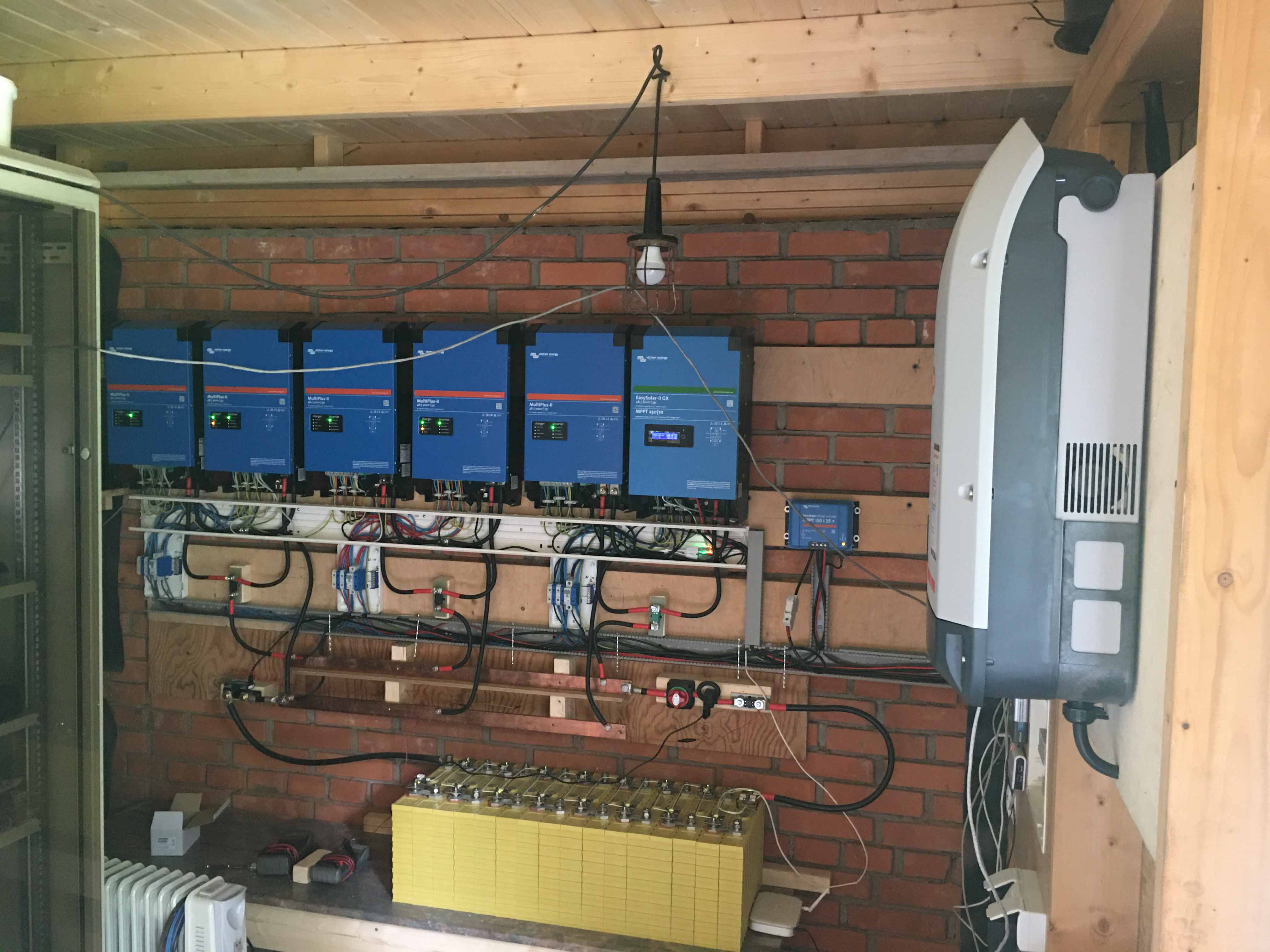
For last 3 months I trying to set-up 3 phase/parallel system out of one EasySolar-II and 5 MultiPlus-IIs.

First, in June 2020 I purchased ES-II and 2 MP-IIs and set-up my 3 phase system.

After couple months I realized that 2.4kW per phase is not enough for my house.

Decided to add 3 MP-IIs in parallel.

Asked my Victron supplier if there is a MP-II still compatible with my MP-II for parallel operation.

In turn he asked Victron the same question and got the positive answer.

"There is no problem to connect the actual produced unit in parallel to existing. The only thing is - firmware must be identic (which means that the units are identic also)."

At the beginning of 2021 I received 3 new MP-IIs.

To make this story short, after setting all up I have a problem with load balancing in all 3 parallel channels.

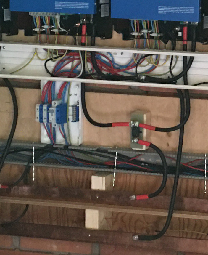
All wires on the DC and AC are equal lengths from the point they split to master and to slave.

On DC side wires are 35mm2 (around 50cm long from the split point) and on the AC side 6mm2 (around 60 cm long from the split point).
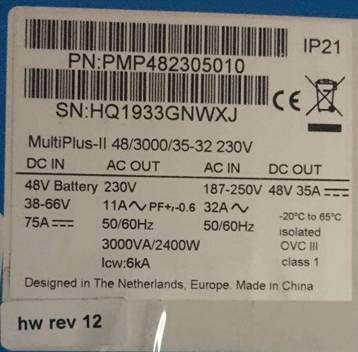
FWs are identical.

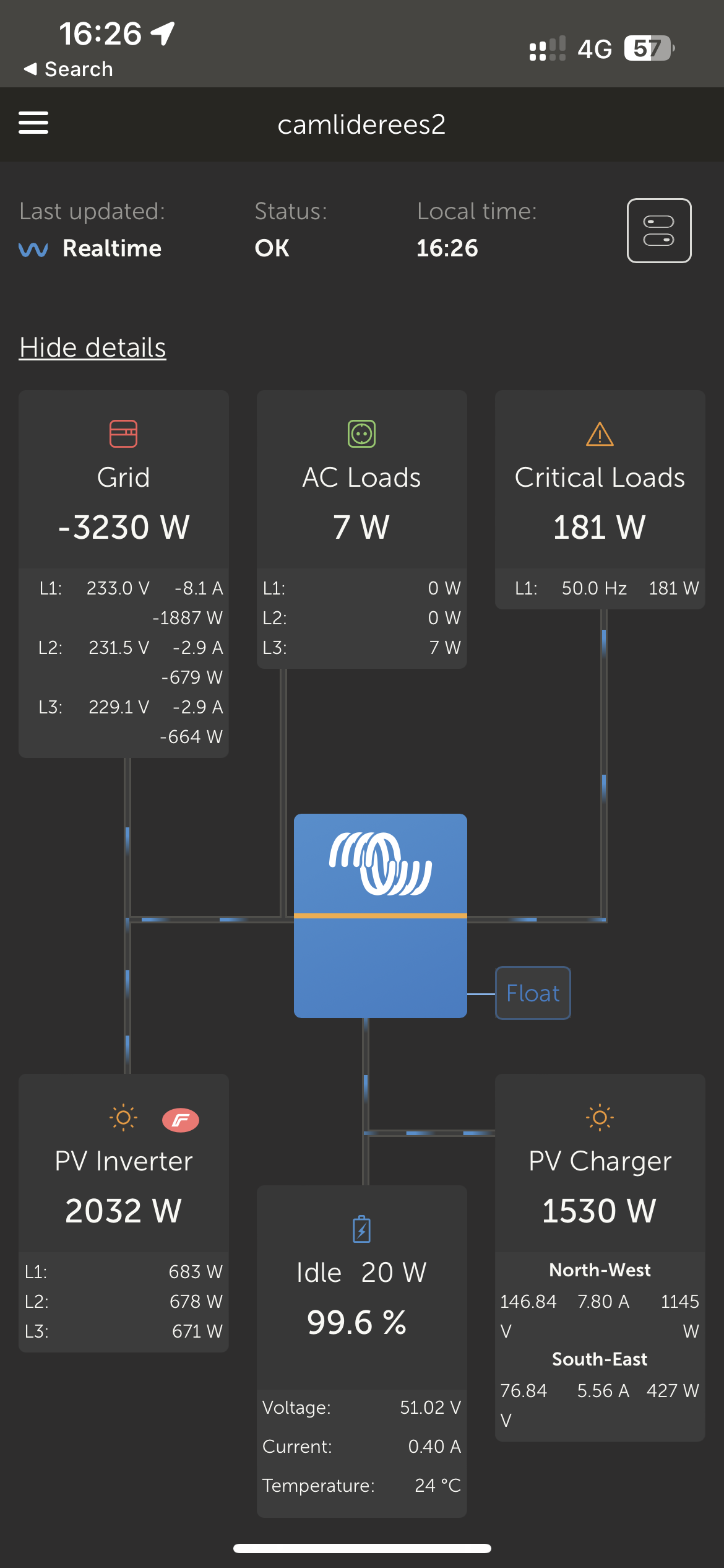
I am getting the following results when each phase is, one by one, loaded with 2.4 kW resistive load.

L1 Total 66A, Master 38A, Slave 28A

L2 Total 54A Master 32A, Slave 22A

L3 Total 55A, Master 32A, Slave 23A

Any suggestions how to make the currents equal?

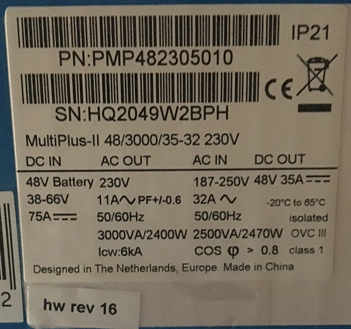
The stickers on the boxes show the model numbers and part numbers of the first and the second batch.

old.jpg

new.jpg


Multiplus-IIbattery charging
new.jpg (211.0 KiB)
old.jpg (192.3 KiB)
2 comments
2 |3000

Up to 8 attachments (including images) can be used with a maximum of 190.8 MiB each and 286.6 MiB total.

shaneyake avatar image shaneyake commented ·

Can you post some photos of the install? Especially of how the breakers are all wired? Are you using bus bars in the DB or do you have wire jumpers?

0 Likes 0 ·
marekp avatar image marekp shaneyake commented ·

Thank you @shaneyake,

Here are some picts to answer your questions.

phase-l2.jpg

view.jpg

0 Likes 0 ·
phase-l2.jpg (219.9 KiB)
view.jpg (446.9 KiB)
8 Answers
marekp avatar image
marekp answered ·

Hello to all,

The last update.

Two days ago I replaced MultiPlus-II with hw rev12 to the new unit. (it had no hw revision sticker).

Load test showed equal load balancing.

Thank you Victron for decisive action in dealing with my problem.

Best Regards to all.

1 comment
2 |3000

Up to 8 attachments (including images) can be used with a maximum of 190.8 MiB each and 286.6 MiB total.

Thanks for the update @MarekP, happy to hear you got a good outcome.
0 Likes 0 ·
Kevin Windrem avatar image
Kevin Windrem answered ·

AC input wiring should also match in length. (Obviously that won’t make a difference when inverting.)

As I understand it, in parallel operation, the inverters all run the same duty cycle so current differences will be due to different path resistances (AC load and DC).

Make sure all connections are tight and maybe even the same torque.

LONGER AC wiring might help.

If all else fails, you could adjust AC load wire lengths to empirically balance loads: increase lengths on the inverter with higher current.


6 comments
2 |3000

Up to 8 attachments (including images) can be used with a maximum of 190.8 MiB each and 286.6 MiB total.

marekp avatar image marekp commented ·

Thank you @Kevin Windrem,

I know that path resistance is important, but as I can control what is happening outside MP-II, I have no control what is inside of it.

My main question is what is the difference in internal resistance between hw rev 12 and hw rev 16.

All connections are tight and since the problem is identical in all 3 phases I would not think that I have here the random problem.

To me it is systemic.

I can play with the wire lengths, but having only 60cm to play with, does not give much confidence that I will get it fixed this way.

Do you know what is the internal resistance of MP-II?

Better question is what is, what is the difference in internal resistance between MP-II hw rev 12 and hw rev 16?

I can also rearrange my MP-IIs so only one phase have 2 different units but that would mean different hardware in one phase.

0 Likes 0 ·

I agree with @Kevin Windrem here.

There is nothing that can be done about any internal variations to the resistance between the MultiPlus-IIs - but what you CAN do is increase the resistance on the AC output side to make those internal variations negligible.

Either by reducing the AC input and output wiring diameter (if safe to do so), or increasing the length.

There is some more detailed engineering in the Output Resistance section of this document - https://www.victronenergy.com/live/_media/ve.bus:rva_-_theory_on_wiring_large_systems.pdf

It is a common tendency to slightly oversize wiring in power systems - however for parallel Victron systems - this will lead to imbalance issues. So better to get the AC wiring size only just as big as you need and no bigger.

0 Likes 0 ·
marekp avatar image marekp Guy Stewart (Victron Community Manager) ♦♦ commented ·

Hi @Guy Stewart (Victron Community Manager),

I also agree with @Kevin Windrem and I already tried to use AC wires with smaller diameter.

If you look at the results I posted, phase L1 had AC in and out wires 2.5mm2 when L2 and L3 6mm2.

As you can see the difference is maybe 1 or 2% on the imbalance values between L1 and L2 or L3..

The document you posted a link too I know and because I know it I asked a question about the difference in internal resistance between hw rev 12 and hw rec 16 of my MP-IIs.

This info will allow me to calculate the length of the AC cables that would make sense.

I would like to know if I have to make AC cables 10 meters long or 1 meter would be sufficient.

Do Victron have the info on the internal resistance of their different batches of production?

I do not thing the problem is related to the single unit since it is identical on all 3 phases.

0 Likes 0 ·
markus avatar image markus ♦♦ marekp commented ·

Hi Marek,

"Do Victron have the info on the internal resistance of their different batches of production?"

I have asked, if this info is somewhere available, but unfortunately it is not.

BR


0 Likes 0 ·
marekp avatar image marekp markus ♦♦ commented ·

Hi Markus,

I did some calculations based on the link posted by Guy.

On DC side.

Rin= (1 -η)*Pin / Iin² = (1 -η)*Vin/ Iin

Rin for MP-II comes out to be 50mOhm when eff is 95% and 94mOhm when is closer to reality at 90%.

DC wire

35mm2 has 0.48 mOhm/m and I have 0.5m of it in each branch.

On AC side.

Rout= ((1-η) / η)*Vout/ Iout (when P=3000VA Vout=230V Iout=13A)

Rout for MP-II comes out to be 931mOhm when eff is 95% and 1966mOhm when is closer to reality at 90%.

AC wires.

I have 0.58m in each branch on AC-in and 0.58m in AC-out

6mm2 has 2.8 mOhm/m

2.5mm2 has 6.7 mOhm/m

Do you see a problem on DC or AC side?

To have 2.5mm2 AC wire resistance close to Rout I would need close to 200m of it and it is ridiculous. :(

Where did I make mistake in my calculations?

0 Likes 0 ·
marekp avatar image marekp Guy Stewart (Victron Community Manager) ♦♦ commented ·

Hi @Guy Stewart (Victron Community Manager),

After reading this:

There is nothing that can be done about any internal variations to the resistance between the MultiPlus-IIs - but what you CAN do is increase the resistance on the AC output side to make those internal variations negligible.

I took out the calculator and attempted to calculate the length of the wire on the AC-out to "make those internal variations negligible"

Rout= ((1-η) / η)*Vout/ Iout (when P=3000VA Vout=230V Iout=13A)

Rout for MP-II comes out to be 931mOhm when eff is 95%

and 1966mOhm when is closer to reality at 90%.

The currents ratio between Master and Slave is 22A/32A and that suggests the internal resistance ratio is the same.

You might say that outside wires are adding to that restance and you will be correct but.

The presentation, from the link you posted, suggests that main reason for the imbalance comes from AC-out wire difference in resistance between Master and Slave branches.

When the Rout is measured in Ohms the resistance of the AC-out wires is measured in miliOhms, there is no way those wires can have significant influence on the total resistance in the Master and Slave branches.

In this case, Rout difference between hw_rev_12 and hw_rev_16 is so big that there is no way to compensate that difference by making AC-out wires longer even when using their minimal diameter.

Do you still agree with the Victron statement that:

"There is no problem to connect the actual produced unit in parallel to existing. The only thing is - firmware must be identic (which means that the units are identic also)."

Only 2 or 3% difference in efficiency of old and new unit would be enough to cause this imbalance.

Or maybe I made a big error in my calculations.

Please tell me that I did.

Regards,

Marek


0 Likes 0 ·
marekp avatar image
marekp answered ·

Hello to all that follow this problem,

I have an update.

After not getting much of the answer to my problem here, I asked Vicron service.

Couple e-mails were exchanged.

Finally Daniël Boekel suggested an experiment to pinpoint the source of the problem.

Two units switched places making two pairs of the same revision and only one comprised of MP-II rev12 and MP-II rev16.

Results of imbalance testing are as follows:
Resistive load 2600W (space heater) on each phase, one by one.
Battery fully charged.
No other loads.
Sun was down so no charging from MPPTs or Fronius.

Phase L1 (Master - EasySolar-II and Slave - MultiPlus-II hw rev 12)
Total DC current 53.2A
Master 26A
Slave 27.2A
AC-out wires 2.5mm2, 58cm long

Phase L2 (Master & Slave - MultiPlus-II hw rev 16)
Total DC current 53A
Master 25.9A
Slave 27.1A
AC-out wires 6mm2, 58cm long

Phase L3 (Master - MultiPlus-II hw rev 12, Slave MultiPlus-II hw rev 16)
Total DC current 54.3A
Master 31.9A
Slave 22.4A
AC-out wires 6mm2, 58cm long

As you can see MP-II rev12 and MP-II rev16 cannot work together in parallel.

As a result, Victron made a decision to replace one MP-II rev12 with MP-II rev16 so all 3 phases will have units from the same revision. (one phase with two rev12 units and two phases with two rev16 units)

The exchange has to go through my Victron dealer because he is to submit RMA document.


1 comment
2 |3000

Up to 8 attachments (including images) can be used with a maximum of 190.8 MiB each and 286.6 MiB total.

Phil Gavin avatar image Phil Gavin commented ·
Thank you for taking the time to provide this valuable feedback.
0 Likes 0 ·
Robert Boerescu avatar image
Robert Boerescu answered ·

I have just bought a new mp2 3000 to put in parallel with my easy solar 2 3000 assuming that it should be compatible. How can I see the hw revision? Will an eventual slight load inbalance cause any issues?

I cannot find a guide to parallel the easysolar, only the one for MP2s. I suppose I will need the mk3 to usb adapter which I do not have now. Also in the video we are suposed the disconnect the cerbo when doing the vebus config but I do not think this is easy to do in an easy solar 2 gx.

Thanks!

1 comment
2 |3000

Up to 8 attachments (including images) can be used with a maximum of 190.8 MiB each and 286.6 MiB total.

nickdb avatar image nickdb ♦♦ commented ·

Some recommended reading:

https://www.victronenergy.com/live/ve.bus:manual_parallel_and_three_phase_systems

and the wiring unlimited guide.

Symmetrical cabling is key, that may be difficult with the different formfactors.

Age of inverters also matters, if there is a biggish gap it may not work well.

You will need a clamp meter for testing.

Systems are never perfectly balanced, the imbalance will vary.

Using the internal GX may also be limiting for a system like this, you may want to consider disconnecting it and getting an external Cerbo.

Personally I would have sold the easy solar and replaced it with discreet components, an unhappy parallel system isn't fun for anyone.


0 Likes 0 ·
marekp avatar image
marekp answered ·

How old is your EasySolar-II compare to the new MP-II?

There should be no problem if they are less than a year apart.

Inside EasySolar-II is the same inverter/charger as MP-II, so it is like connecting parallel two MP-II.

Disconnecting GX is not necessary for setting two MP-II in parallel.

1 comment
2 |3000

Up to 8 attachments (including images) can be used with a maximum of 190.8 MiB each and 286.6 MiB total.

Robert Boerescu avatar image Robert Boerescu commented ·
Unfortunately it is more than one year
0 Likes 0 ·
Robert Boerescu avatar image
Robert Boerescu answered ·

Reading more I see that it is possible to put them in two thirds of a three phase system. My easy solar is on phase one. I could put it on phase 2 to give surplus solar to the loads on phase 2. Ac out is used only for some critical loads.

1690378074120.png


1690378074120.png (359.5 KiB)
2 |3000

Up to 8 attachments (including images) can be used with a maximum of 190.8 MiB each and 286.6 MiB total.

marekp avatar image
marekp answered ·

@Robert Boerescu

The problem with parallel setup could be related to the hardware change that happen late 2020/early 2021.

If your old ES-II and the new MP-II are made after the respecting dates, they have a chance to work OK in parallel.

screen-shot-2023-07-26-at-34519-pm.png


2 |3000

Up to 8 attachments (including images) can be used with a maximum of 190.8 MiB each and 286.6 MiB total.

Robert Boerescu avatar image
Robert Boerescu answered ·

I set it up yesterday with and older easy solar 2 and a new mp2 and it seems to work stable so far. It is a split 120 degree system in a three phase ac environment. with ESS. It will be a three phase when I can purchase the third one and eventually put the Fronius on the AC out.

vrm2.png


vrm2.png (118.4 KiB)
1 comment
2 |3000

Up to 8 attachments (including images) can be used with a maximum of 190.8 MiB each and 286.6 MiB total.

marekp avatar image marekp commented ·
@Robert Boerescu

Problems with balancing were happening only when you tried setting up a parallel system using units that are far apart in production dates.

Two, three phase system should not have this problem.

1 Like 1 ·

Related Resources

Additional resources still need to be added for this topic

MultiPlus-II Product page 

MultiPlus-II Manual

MultiPlus-II 230V Datasheet 

VE.Bus Error codes