question

mrlorin avatar image
mrlorin asked

Victron provides conflicting installation instructions for Smart Shunt

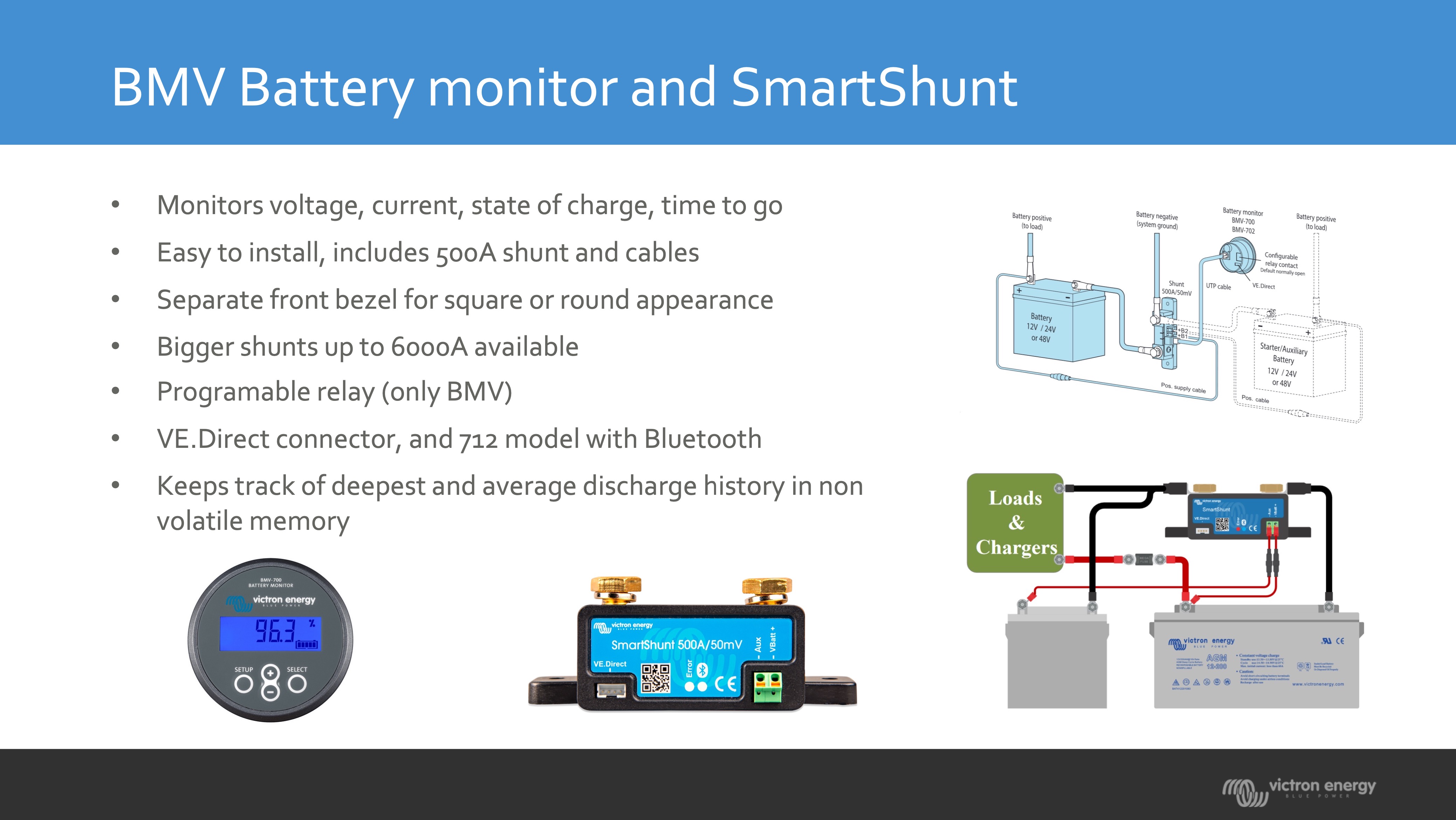
Victron provides conflicting technical information on the correct way to connect a DC Smart Shunt in dual battery system.
I plan to use the aux input to monitor the starter battery voltage.

Which side of the Victron Smart Shunt should the starter battery negative terminal be connected?

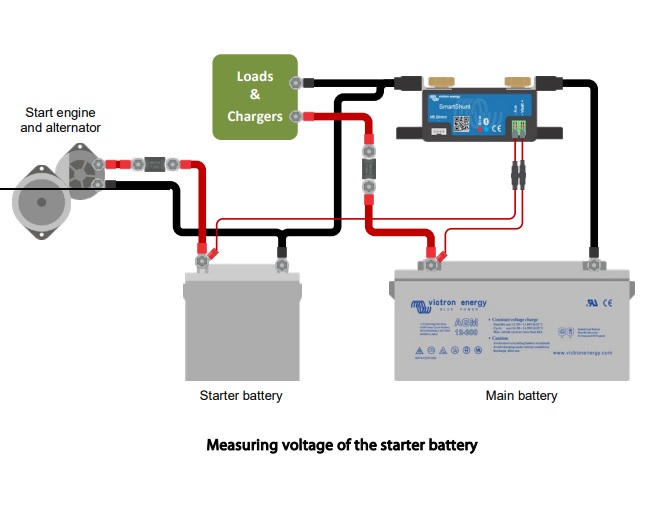
I think this is correct with the starter battery connected to the smart shunt load minus.
victron.jpghttps://www.dropbox.com/s/86t70756l1...ctron.jpg?dl=0

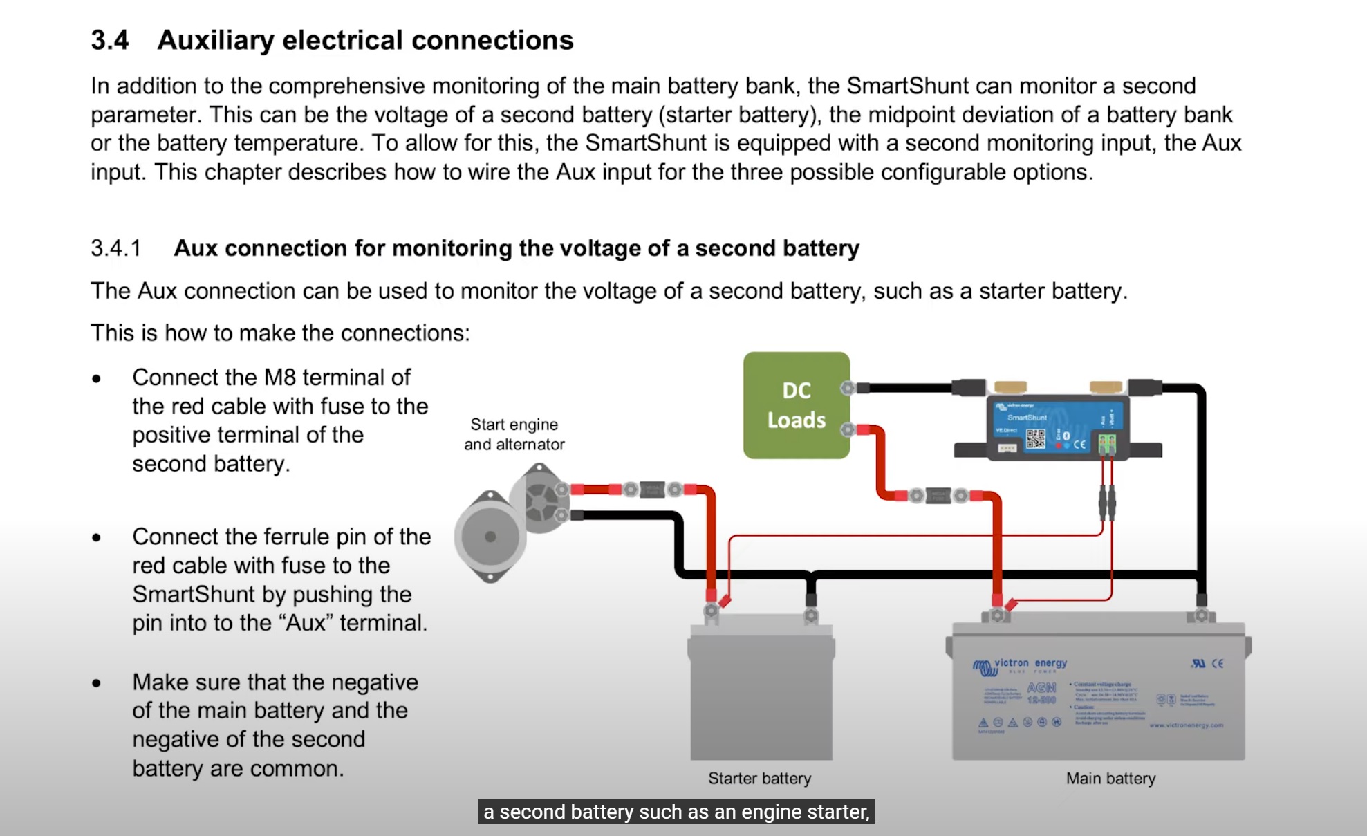
However this picture from the Victron instruction video shows the starter battery negative connected to the smart shunt battery minus.

dc-shunt-victron.jpghttps://www.dropbox.com/s/istly33coe...ctron.jpg?dl=0
https://www.youtube.com/watch?v=0HG4GiH9su8

@ time 8:00

I also plan to install a voltage sensitive relay to enable the alternator to charge the system battery and the solar panel to charge the start battery.

https://www.kickassproducts.com.au/B...groupid=&adid=

If the start battery is linked to the shunt battery negative any current flowing through the VSR would not be measured by the shunt.


When and why should the starter battery negative be connected to the Smart Shunt battery minus instead of load minus? (It seems incorrect)


Apologies for re-posting this but my first post has zero answers.

I think an answer from Victron is necessary because this question is causing heated debate on the cruisersforum. I have asked Victron via the dealer network for a response.

SmartShunt
victron.jpg (48.6 KiB)
dc-shunt-victron.jpg (381.1 KiB)
2 |3000

Up to 8 attachments (including images) can be used with a maximum of 190.8 MiB each and 286.6 MiB total.

5 Answers
kevgermany avatar image
kevgermany answered ·

You asked for a reply from Victron. This comes over as you saying that the non Victron members don't know what they're talking about, insulting us. So we don't reply.

The shunt needs a common reference negative. This is its battery side. Battery voltage, both starter and house are compared to that through separate cables. If they do not have a common reference negative the two independent systems can and will end up at different relative potentials which affects voltage measurements. By design and construction the shunt can only monitor one battery/battery bank fully. It can only measure voltage, not current on the starter battery. There should be no load on the house battery that can bypass the shun, hence no other connections.


2 |3000

Up to 8 attachments (including images) can be used with a maximum of 190.8 MiB each and 286.6 MiB total.

kevgermany avatar image
kevgermany answered ·

Plenty of non Victron people here who can answer. If you specifically ask for Victron input, then you route is via the dealer. This community is manned by unpaid volunteers, with occasional Victron input. Coming on here, the way you have, says to us that you don't want our help.

The bottom line is that you need to understand how the shunt works. The Victron diagram is correct. The confusion is your assumptions and lack of knowledge.


2 |3000

Up to 8 attachments (including images) can be used with a maximum of 190.8 MiB each and 286.6 MiB total.

mrlorin avatar image
mrlorin answered ·

Quote "Plenty of non Victron people here who can answer"

You are the first to reply and you haven't given an answer. Just insults.

Quote: "This community is manned by unpaid volunteers, with occasional Victron input. Coming on here, the way you have, says to us that you don't want our help. "

Please explain " Coming on here, the way you have"

I asked for clarification of contradictory installation instructions that are published on the Victron website.

I am attempting to contact Victron technical support via the dealer network. I have also posted this question on the cruisersforum where there is now a lively debate with several suggestions that I contact Victron directly for clarification.

Quote "The Victron diagram is correct. "

You need re-read my question. There are 2 diagrams from Victron that disagree. (hint: it is in the title)

Which one is correct? Why?

I understand how a shunt works. I don't know how the Smart Shunt aux input can measure voltage when varying current through the shunt is causing a varying voltage drop and how that affects the aux input?

Quote "The confusion is your assumptions and lack of knowledge."

Yes I assume that Victron should give consistent installation instructions.

Yes my lack of knowledge is why I posted this.

Please enlighten me.


2 |3000

Up to 8 attachments (including images) can be used with a maximum of 190.8 MiB each and 286.6 MiB total.

mrlorin avatar image
mrlorin answered ·

Thankyou kevgermany for your answer.

I have received a reply from my local Victron dealer, who says that the diagram in the video @8:00

is not correct. https://www.victronenergy.com/battery-monitors/smart-battery-shunt#video

"The manual entry and diagram have been updated to show the correct connection. Please follow the latest manual information."

https://www.victronenergy.com/media/pg/SmartShunt/en/installation.html#UUID-a10646e3-b62d-00ab-0abb-7f807edfb62f

Perhaps Victron will also update their instruction video to avoid confusion?

1 comment
2 |3000

Up to 8 attachments (including images) can be used with a maximum of 190.8 MiB each and 286.6 MiB total.

Hi @mrlorin,

Thanks for the report - I have just updated the Online Training videos and linked PDF documents with this corrected diagram.

cleanshot-2022-08-26-at-190006.jpg


The YouTube video is still to be updated but will be done shortly - YouTube doesn't make it as easy to correct a video :(

0 Likes 0 ·
klim8skeptic avatar image
klim8skeptic answered ·

Please enlighten me.

Funny post, considering I answered your initial post 20 hours ago.


2 |3000

Up to 8 attachments (including images) can be used with a maximum of 190.8 MiB each and 286.6 MiB total.