question

idat avatar image
idat asked

Programmable relay not AC out put 2 driven by SOC

Hey

I have 3 stage load shedding i want to set up to load shed based on SOC

I had seen in the manual that there is only the below

6) Programmable relay that can a.o. be set for general alarm, DC under voltage or genset start/stop function AC rating: 230 V / 4 A DC rating: 4 A up to 35 VDC, 1 A up to 60 VDC


I'm trying to achieve the below

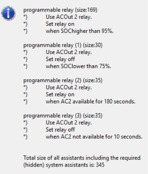
Stage 1 Drops out AC circuit at 70% SOC and on at 75% :Relay??

Stage 2 Drops out general power at 50% and on at 55% : Relay??

Stage 3 Essentail drops out at 25% and on at 30% : AC output 2

Thanks in advance

SOCRelay
1 comment
2 |3000

Up to 8 attachments (including images) can be used with a maximum of 190.8 MiB each and 286.6 MiB total.

Matthew Walsh avatar image Matthew Walsh commented ·

Assumption is that all loads that you want to control by the 3 stages are on AC Output 2?

If so then,

Stage 1 would need to an external contactor that controls the AC circuits you want to drop at 70%, your programmable relay would make use of one of the many relay in the inverter to control the coil of the contactor.

Stage 2 would also need to be the same with another external contactor

Stage 3 would be a straight programmable relay that uses AC output 2 relay to open when 25% reached and then close when 30% is reach.

0 Likes 0 ·
4 Answers
Henrik avatar image
Henrik answered ·

I realized a similar function with the built-in assistants via VE.Configure Multi software to control the programmable relais of the Victron Quattro

1 comment
2 |3000

Up to 8 attachments (including images) can be used with a maximum of 190.8 MiB each and 286.6 MiB total.

iruizh avatar image iruizh commented ·

Hi @Henrik ,

Could you expand more on how I do it,

thank you

0 Likes 0 ·
Henrik avatar image
Henrik answered ·

Hi @iruizh

I control the AC2 output relay of the second AC output of the Quattro by SOC levels using the "programmable relay" assistant for ACOut 2 relay

What you could do for your stage 3 is to overwrite the default by using the following little programmable relay assistants:

programmable relay: Open AC2 output relay if SOC < 25%

programmable relay(1): Close AC2 output relay if SOC >30%

Someone else in the forum put the following picture which shows some similar assistant programs (he uses four different " assistant programs" to open/close this AC2 output relay).

Important note: The logic of the assistants require the correct sequence of this assistants. It is processed from top to down.


In regard of your stage 1 and 2: what do you mean with "general power" and "AC circuit", is that on the input side or output side?

2 |3000

Up to 8 attachments (including images) can be used with a maximum of 190.8 MiB each and 286.6 MiB total.

iruizh avatar image
iruizh answered ·

Hi @Henrik ,

about stage 1 and 2, is @IDAT project, I think what it refers to is how to shed different categories of loads, such as "AC circuit" = Air conditioner circuit ? and "general power" = rest of loads , and finaly "essential loads" = loads supported like no break (UPS)

I release a question yesterday (link) , and your comment help me, I'll try this weekend to implement,

Thank you

Benjamin


2 |3000

Up to 8 attachments (including images) can be used with a maximum of 190.8 MiB each and 286.6 MiB total.

Alexandra avatar image
Alexandra answered ·

@IDAT

It is possible to use the generator assistant to drive a relay with a contactor. the relay can drive k1, k2 or aux relays. depending on your inverter model there can be several options.

1673032067898.png

then there is node red and you will need some smart switches.


1673032067898.png (25.2 KiB)
2 |3000

Up to 8 attachments (including images) can be used with a maximum of 190.8 MiB each and 286.6 MiB total.

Related Resources

Additional resources still need to be added for this topic