question

robster avatar image
robster asked

Victron connect ESS issue

Hi All,

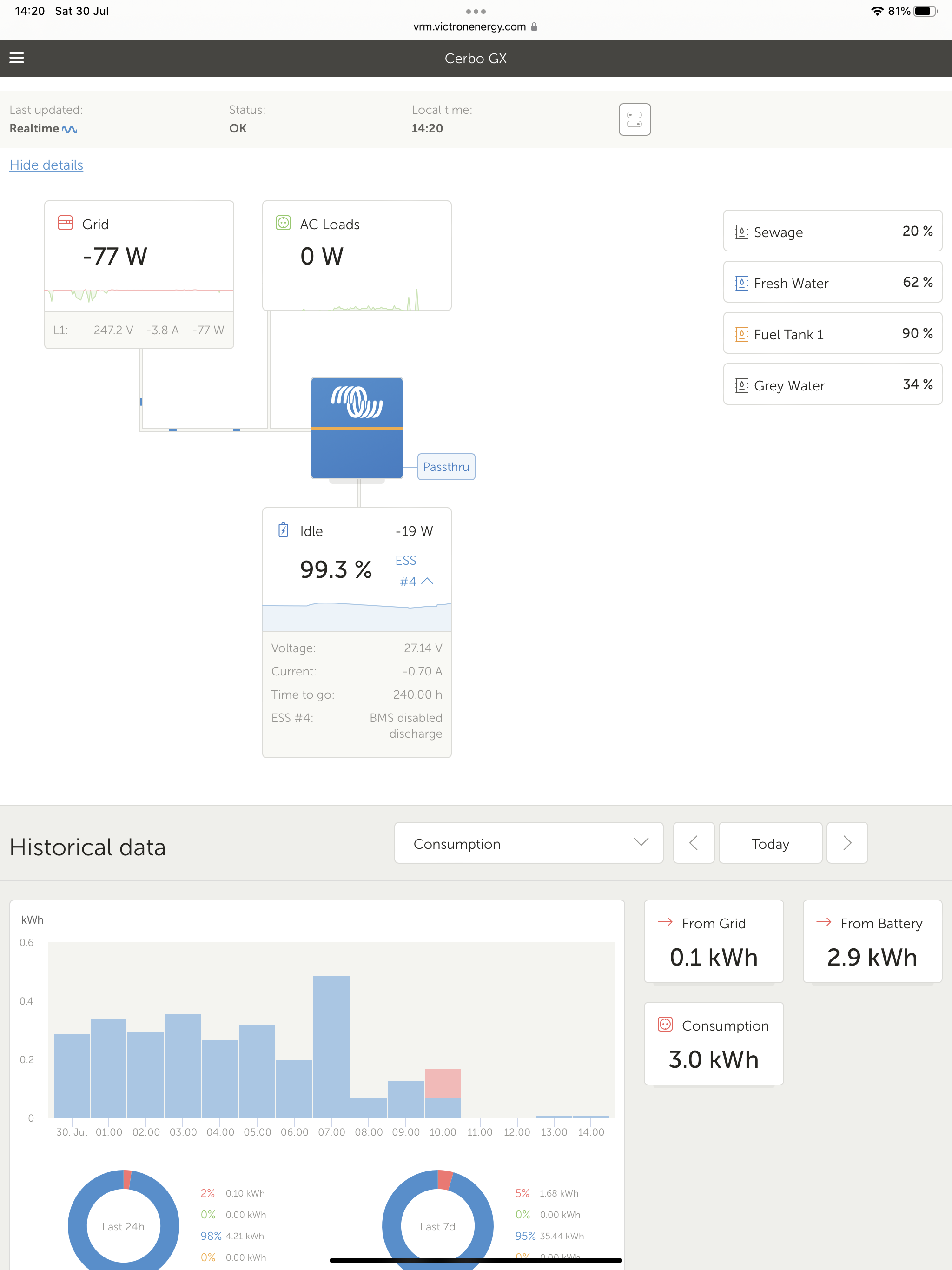
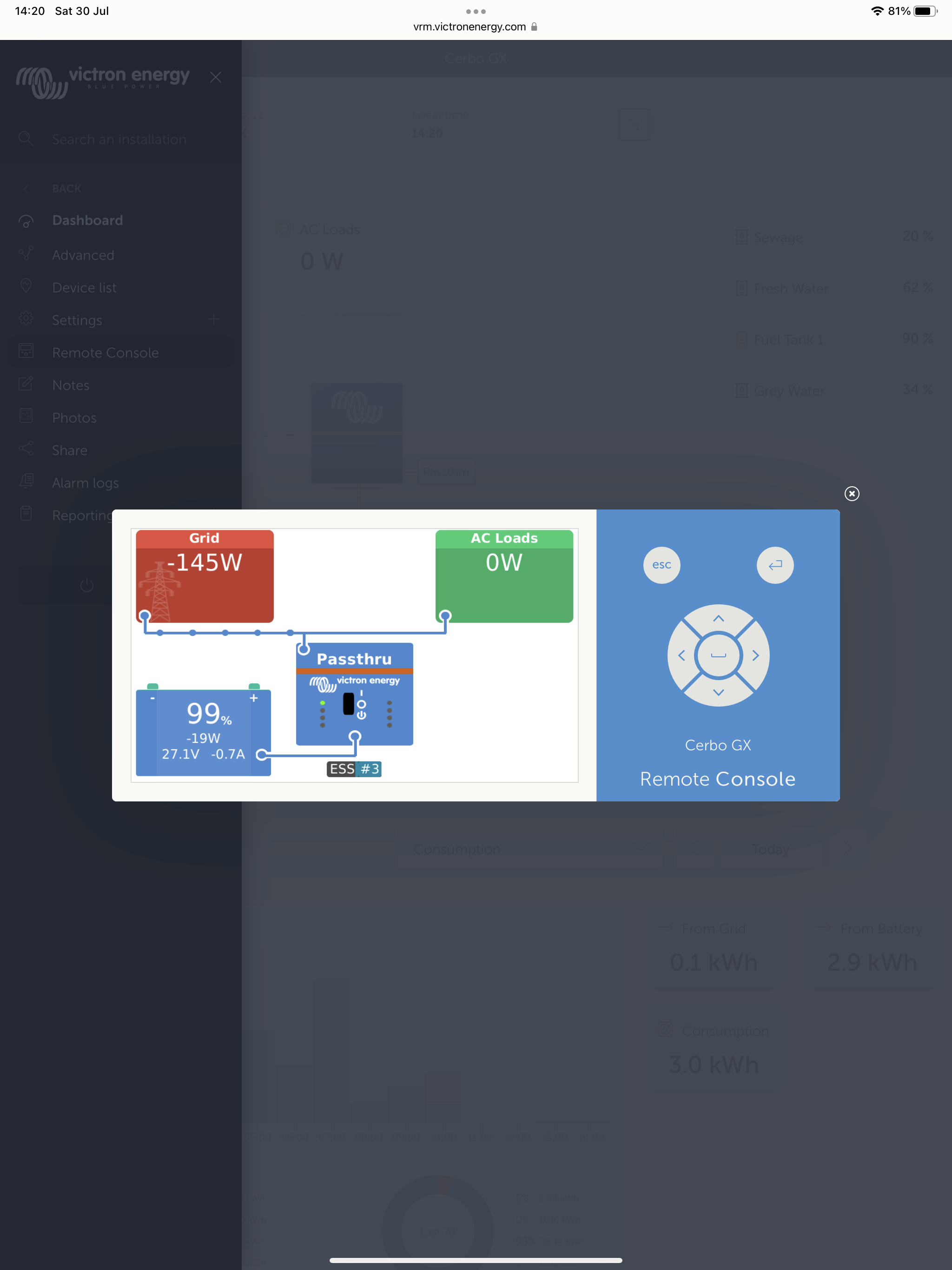
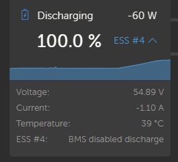
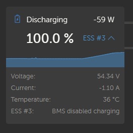
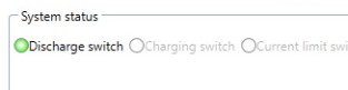
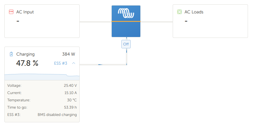
Does anyone know why the remote console screen shows ESS #3 (BMS disabled charge) while on Victron Connect it shows ESS #4 (BMS disabled discharge)?

The inverter remains in passthru until battery cell voltage naturally decays sufficiently.

I understand the requirement to disable charge, but why does it also prevent the ability to discharge?

Thanks in advance.

Rob.


51480450-efef-4dad-8dfd-441a0069246d.png


07320548-86b8-4021-9b4d-a73945e540de.png


Multiplus-IIcerbo gxess discharging
2 comments
2 |3000

Up to 8 attachments (including images) can be used with a maximum of 190.8 MiB each and 286.6 MiB total.

Alexandra avatar image Alexandra ♦ commented ·

@Robster

What BMS do you have and how have you programmed the system?


0 Likes 0 ·
robster avatar image robster Alexandra ♦ commented ·
Hi Alexandra,

It’s an Electrodacus SBMS0 controlling a 24v battery of LiFePo4 cells.

Default settings and operating as a 2 wire BMS.

0 Likes 0 ·
8 Answers
nickdb avatar image
nickdb answered ·

Rob, it really depends what BMS you have and how it has been setup.

The GX will take whatever it is told and obey (depending on the BMS you may be able to view the CCL, DCL, CVL along with min/max cell voltages in the GX under BMS details/parameters, but not all can send this info).

So if the BMS decides to block, the GX will follow. Discharge cutoffs are usually due to low cell voltages (can be imbalanced), the converse is true for Charge limits. You really need to dig into what the BMS is up to, with whatever tools it provides.

In any case it does not look like your battery management/battery is happy.

This can go hand in hand with how your multi is configured and what functionality is enabled on the GX (DVCC).

2 |3000

Up to 8 attachments (including images) can be used with a maximum of 190.8 MiB each and 286.6 MiB total.

robster avatar image
robster answered ·

Hi Nick,

Thanks for taking the time to answer. I’m using an electrodacus SBMS0 as a two wire bms. I believe it’s set up correctly to control the multilplus II inverter.

However, my issue is the discrepancy between the two photos above.

The first screenshot of the VictronConnect shows ESS#4 whereas the photo of the remote console (taken at the same time) shows ESS#3.

I can’t explain why.

1 comment
2 |3000

Up to 8 attachments (including images) can be used with a maximum of 190.8 MiB each and 286.6 MiB total.

nickdb avatar image nickdb ♦♦ commented ·
My bad. The two should agree unless states are alternating. If you do a shift reload on the browser to force a cache flush and load does it persist? Trying to understand if its a timing issue or something broader. Are you able to confirm from the bms which signal(s)/state it is sending?
0 Likes 0 ·
robster avatar image
robster answered ·

The battery is fully charged, so I was expecting the ESS#3 state.

I was wondering why it wasn’t discharging until I saw the ESS#4 on the VictronConnect page.

The BMS is sending just the cease charging signal.

…I don’t get it.

Perhaps it’s a glitch that’ll go away with a future update.

1 comment
2 |3000

Up to 8 attachments (including images) can be used with a maximum of 190.8 MiB each and 286.6 MiB total.

nickdb avatar image nickdb ♦♦ commented ·

Even if it is reporting incorrectly, this won’t prevent the battery discharging. Can you share any screenshots of what the gx is reporting for the bms, what ESS is reporting for error states from the ess tab.

0 Likes 0 ·
robster avatar image
robster answered ·

Thats the point Nick, it is preventing the battery from discharging. It stays in passthru until the battery drops below the threshold again.

Even resetting the system doesn’t allow the battery to discharge.

As for the rest of your reply, I don’t really know what you said.

I’m a dabbler, not an expert.

…can you tell? ;0)

1 comment
2 |3000

Up to 8 attachments (including images) can be used with a maximum of 190.8 MiB each and 286.6 MiB total.

nickdb avatar image nickdb ♦♦ commented ·

No stress, sorry for the waffle.

Point is. If VRM reports "don’t discharge" and the inverter won’t discharge, its not a reporting issue. The “system” is being told not to.

If it were just a reporting issue, the battery would discharge. So there is more to it.

Do you have access to the cerbo/GX console?

If so, the BMS may appear as an entry on the device list.

If it does, there may be info in there that can help.

It's challenging to triage these kind of problems via the interweb.


0 Likes 0 ·
robster avatar image
robster answered ·

I agree, it is difficult & I do appreciate your help.

Unfortunately I’m remote from the system too - I’m currently only able to check it online.

The BMS isn’t connected to the Cerbo directly. There are two normally closed contacts on the BMS. One to inhibit charging, the other inhibits discharging.

So, those wires go directly to the appropriate contacts on the Multiplus II, bypassing the Cerbo.

Perhaps I’ll have to wait until I’m in front of the system before I can continue with the diagnosis

I’m still at a loss to work out why ESS#3 shows on the remote console while the VictronConnect shows ESS#4.

….surely they should be the same, as one is a repeater of the other


2 |3000

Up to 8 attachments (including images) can be used with a maximum of 190.8 MiB each and 286.6 MiB total.

Andy avatar image
Andy answered ·

I have a similar issue using a Seplos BMS connect to a Cerbo via CAN.
If the battery is full, it shows ESS #4 BMS disabled discharging which makes no sense for a full battery.

ess4.jpg

I have done more testing and found that in ~2 out of 10 full charges the message would show correctly as ESS #3 BMS disabled charging.

ess3.jpg

With the next full charge though, it would most likely show ESS #4 again.

My remote console does not show anything, no ESS message at all.

I have only an off-grid installation, so no ESS is activated in my system setup.

The actual switches in the BMS are set correctly, so discharge is active and charge is disabled, if the battery is full.

seplos.jpg

I wonder if this is rather a Victron problem than an issue with the BMS. Or some commands are not getting interpretate correctly? At the end, it's just a message, but I wonder what else is incorrectly submitted or received but just does not show...


Edit:

I'm now seeing the same ESS #3 in the remote console and ESS#4 in the VRM


ess4.jpg (11.4 KiB)
ess3.jpg (11.9 KiB)
seplos.jpg (4.8 KiB)
3 comments
2 |3000

Up to 8 attachments (including images) can be used with a maximum of 190.8 MiB each and 286.6 MiB total.

htech avatar image htech commented ·

Hello Andy have you resolved this issue? I am encountering this same issue with my Seplos BMS and can't figure out how to solve it.

0 Likes 0 ·
zipoman avatar image zipoman htech commented ·
I have same issue :-(
0 Likes 0 ·
dc-generators avatar image dc-generators commented ·
I have the same issue as well. Seplos 10E BMS.
0 Likes 0 ·
columbusmechtech avatar image
columbusmechtech answered ·

Just freshly installed Venus OS, installed louis driver with modifying the conf file to add the inverted voltage and modified the charge and discharge max values which were my only modifications so far, and finally got Venus to talk to the Daly via RS485 or UART (only one can be connected at a time). Currently I am only using Venus OS as a remote monitoring solution for the custom battery I built. I also have ESS #3 showing up for no reason. The BMS is happy and all values are where they should be. It doesnt appear to be actually disabling the charging but I cant tell if it is modulating the charging. I am using a Daly with connection via RS485 and also tried the Daly Uart with same message. If I unplug the RS485 and install the bluetooth to check all through the manufacturer software via phone, everything seems to be fine. screenshot-from-2023-07-11-12-22-07.png


2 |3000

Up to 8 attachments (including images) can be used with a maximum of 190.8 MiB each and 286.6 MiB total.

columbusmechtech avatar image
columbusmechtech answered ·

Made more modifications to my conf file and now the ESS is gone yet the charging appears to be modulating with undesired results, however, my external meter shows the current is not modulating. Ill play around with it some more to see what I can do. I am sure its the settings I fed it. It does appear to be controlling the BMS if you use the RS485 connection but I have not verified this yet.

update: Tried what I could with no good results. Even tried disabling the control (CCCM_CV_ENABLE = False and DCCM_CV_ENABLE = False) It keeps modulating. I think I will use the UART cable and let Daly manage and just be annoyed by the ESS message, its not that bad. I would rather have the message then have my Daly burnt up from modulating current.

Update2: after resetting the bms soc reset and all started working properly on the rs485.

2 |3000

Up to 8 attachments (including images) can be used with a maximum of 190.8 MiB each and 286.6 MiB total.