question

netzerodude avatar image
netzerodude asked

Simple grid connected Quattro 48/10000 and Pylontech battery storage system - No PV

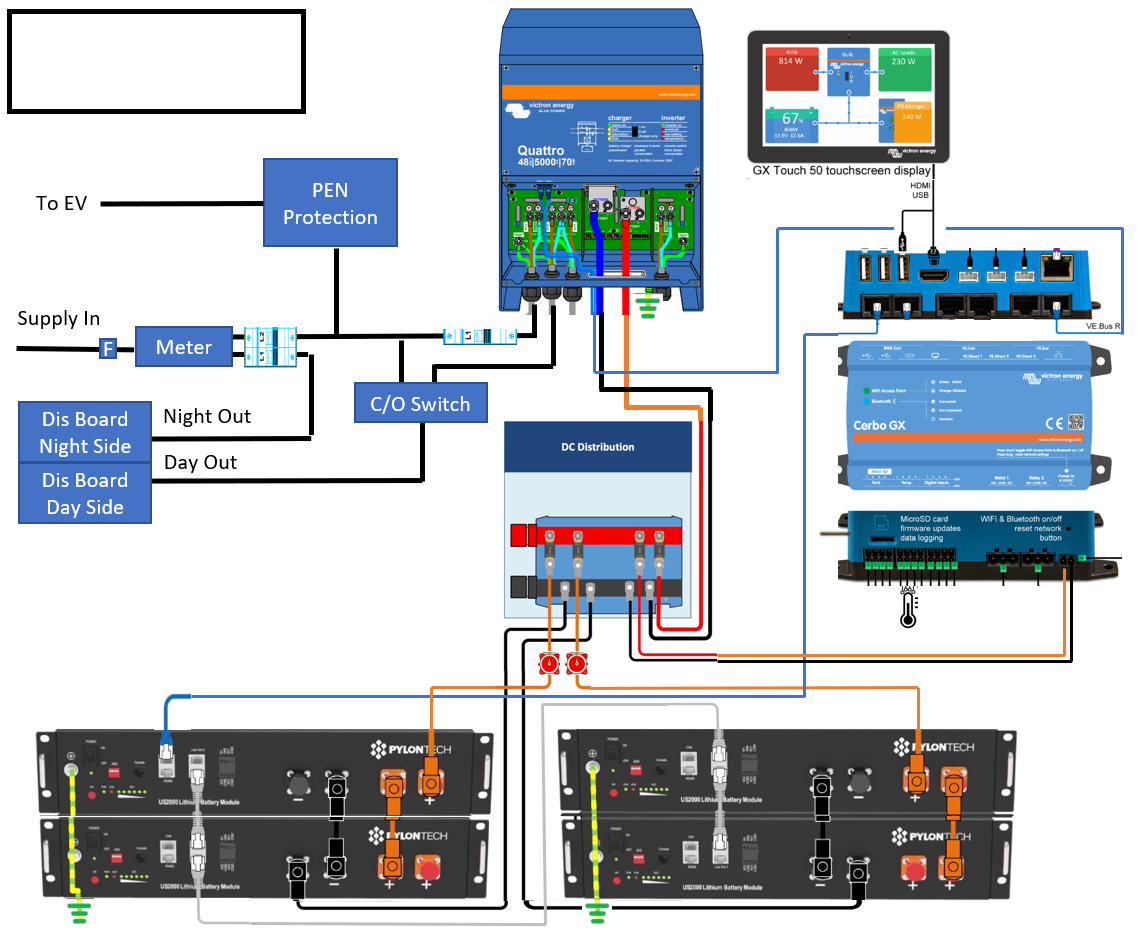
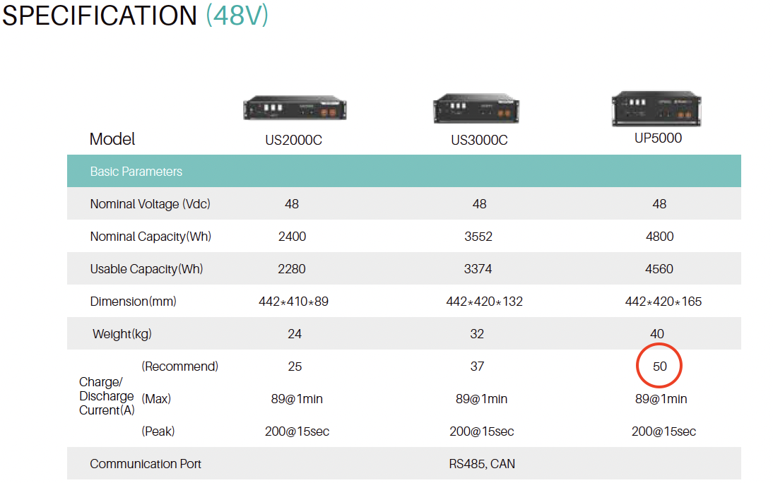
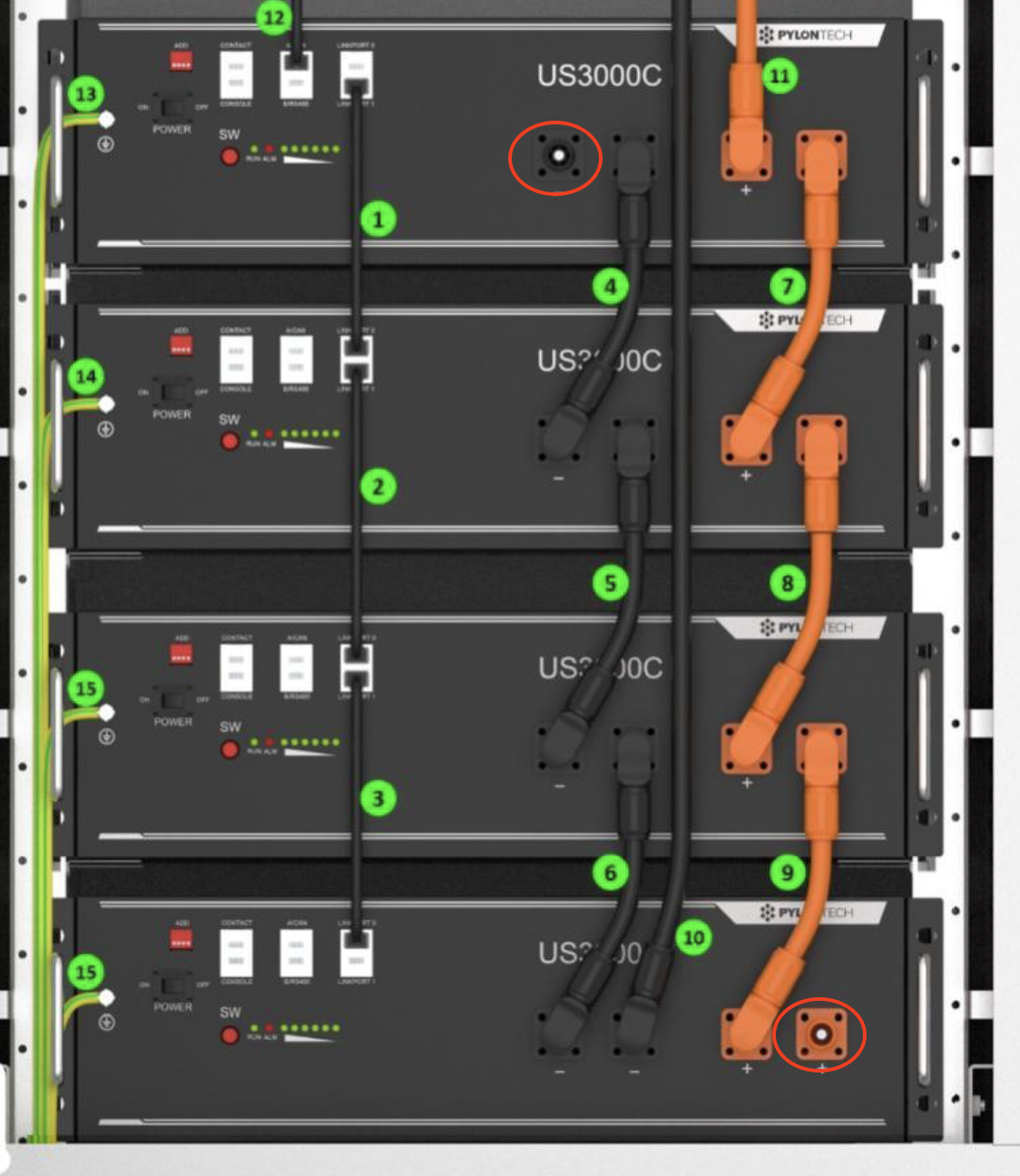
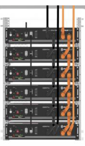
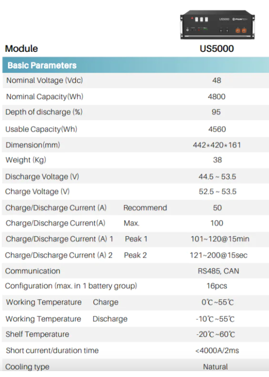
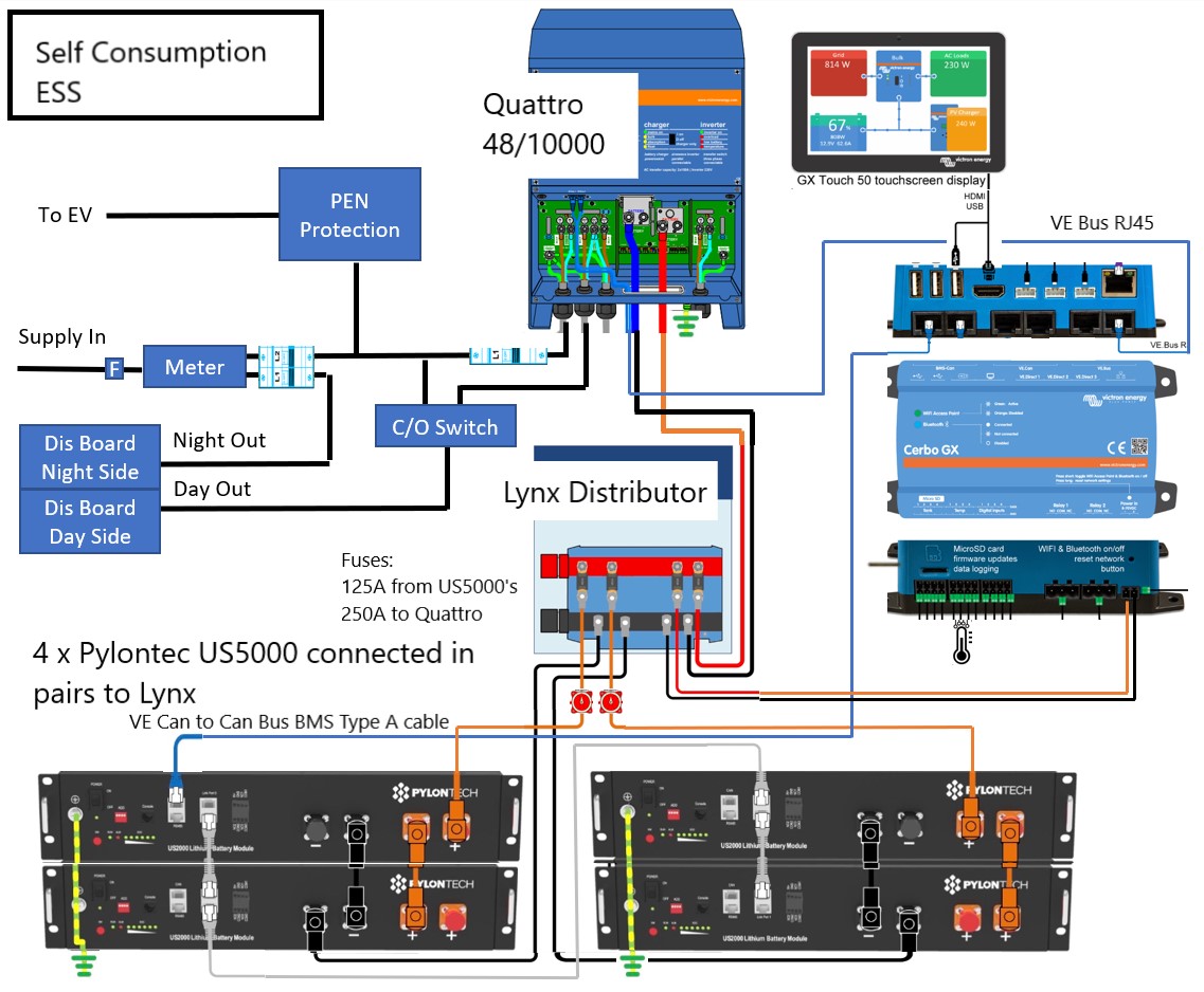
Hi, having taken earlier advice I am now the proud owner of a Quattro 48/10000, 4x Pylontech US5000 batteries circa 19kwh, Cerbo GX, Cerbo GX Touch 50 and this week my electrical supply has switched to EDF GoElectric 35 which gives me 5hrs low rate overnight.

Our house is fully electric and is split economy 7 style.

Night loads such as storage heating/immersion heater being fed from the switched smart meter 5th terminal for 5hrs on low rate overnight. I want to leave this unchanged and is working perfectly.

All other loads are fed from the 24hr smart meter 4th terminal which is both high and low rate depending on the time of the day/night. My EV charger is connected to this and want to continue with this being supplied direct from the grid and not from my batteries, so my understanding is I need to effect changes downstream of this connection.

My simple 24hr use case is

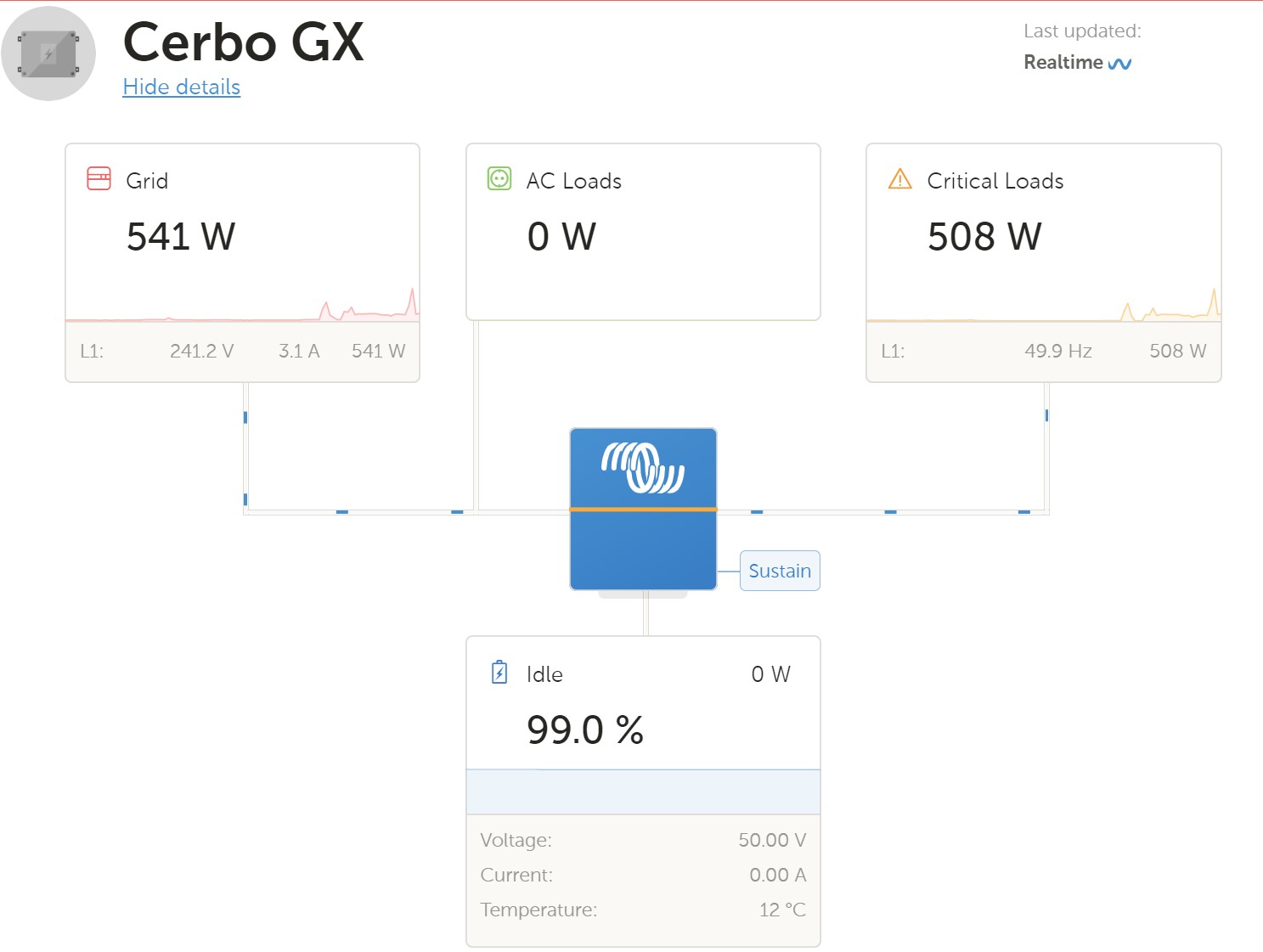
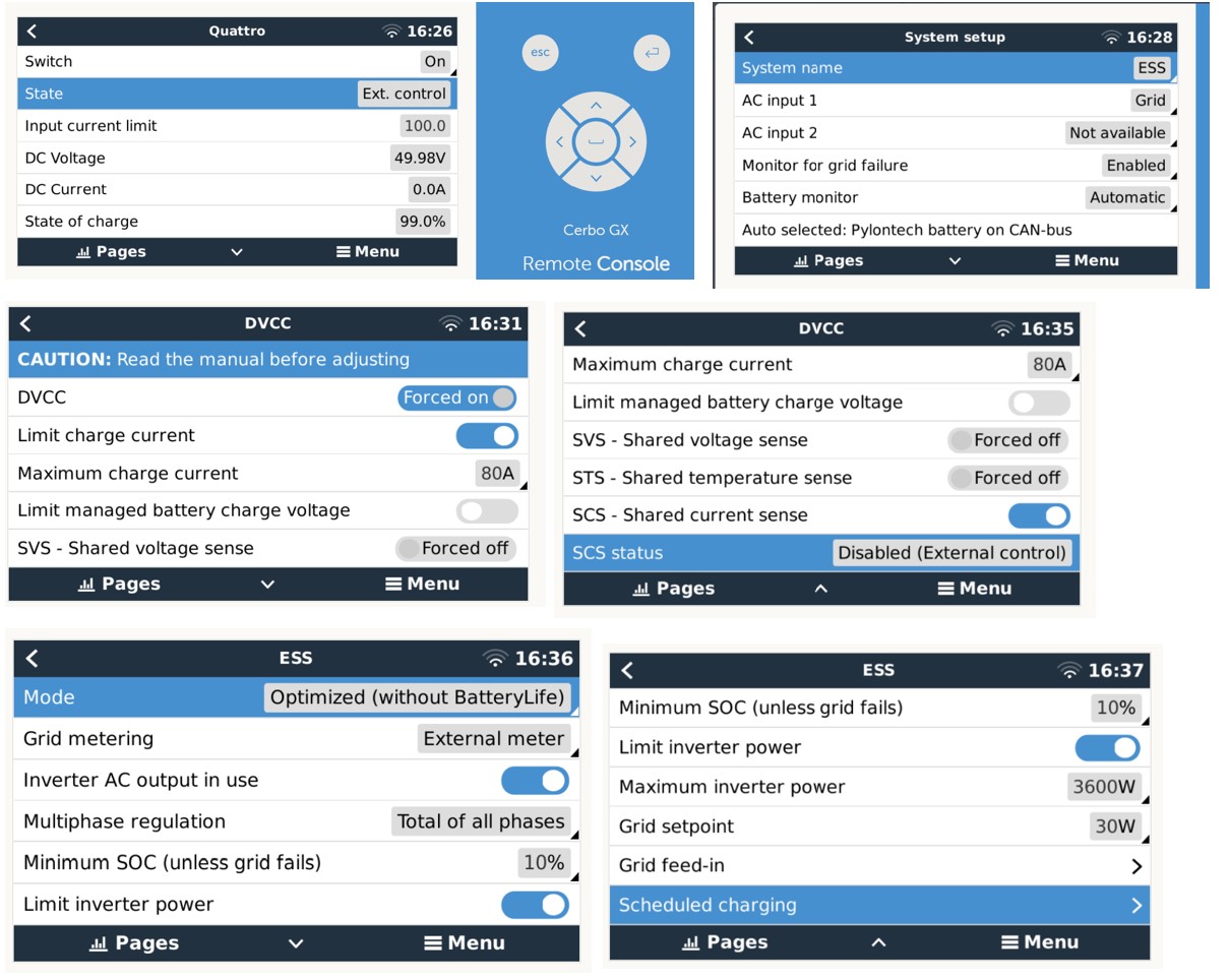
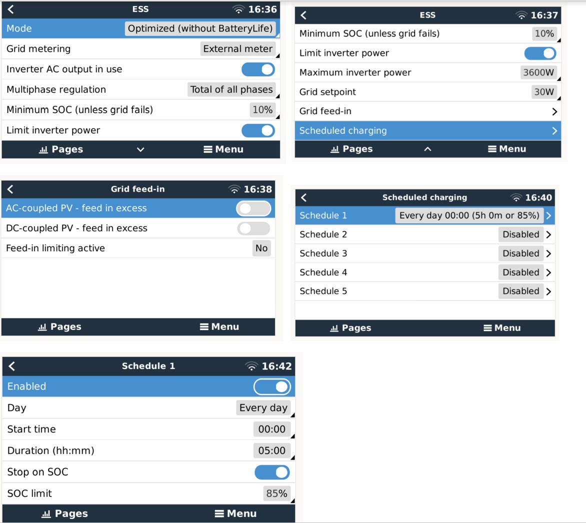
1. Charge batteries overnight during the 5hrs low rate as well as continuing to power all loads. The Quattro 48/10000 invertor is sized to be able to charge my batteries during the 5hrs as long as I keep the batteries above 10degC.

2. When low rate is switched off, use the batteries to power house loads via the Quattro with the grid providing additional power as needed to meet peaks or pick up when the batteries are depleted and awaiting the next overnight charge cycle. By my calcs the quattro / pylontech combination is able to provide circa 4.8kw but will probably limit this to below 3.6kw. My house peaks at circa 8kw on occasion so I will need to draw circa 4.4kw from the grid in addition to the batteries supply for short periods.

I am pretty confident that my purchases can be configured to do all this, but I am struggling to find a definitive way connect everything and was thinking there must be. I do not intend to fit solar due to poor roof orientation.

I would be most grateful if someone can point me in the direction of a detailed diagram that I can use as a starter.

thank you in advance.


Multiplus-IIPylontechquattro 10kva
15 comments
2 |3000

Up to 8 attachments (including images) can be used with a maximum of 190.8 MiB each and 286.6 MiB total.

netzerodude avatar image netzerodude commented ·

Hi @nickdb , after some considerable delays including pylontech supply and changing the inverter to a quattro for anti-islanding requirements ......and taking your good advice on surge currents to check things through and double check myself (btw it did overload on first start but after resetting it was fine), I now have the install complete and part way through commissioning. Batteries charged, ESS assistant schedule set to charge off-peak, but I am struggling to

1. coax it to invert so i can self consume during the peak hours.

2. wondering whether I need to install an energy meter just before the Quattro AC1 in connection as I have an EV charger connection installed upstream which I don't want to draw charge from from the batteries.

I have followed the settings from various sources for the Quatrro and those within the CerboGX but I am now a little stumped. I was wondering whether you or anyone else is able to assist me. I have consulted the info below and followed it. I also attach the VEConfig settings from the Quattro.

https://www.victronenergy.com/live/battery_compatibility:pylontech_phantom

Any help would be of great value, many thanks in advance. For clarity, I have installed a changeover switch (C/O) on the AC Out and an isolator to ACIn In so that I could easily return my house supply to normal in case of problems...which has been very useful. Quattro and Pylontech model numbers are incorrect as I couldnt find a better graphic.

Quattro Settings.TXT

1669573631807blob.jpg

0 Likes 0 ·
1669573631807blob.jpg (420.3 KiB)
sharpener avatar image sharpener netzerodude commented ·

CORRECTION: On reflection I don't think you need a meter where you say. With your topology (and assuming the Quattro is similar to the MultiPlus II with which I am more familiar) the internal current sensor on AC-In should do the same job of preventing backfeed. @nickdb can I expect confirm this.

Looking at yr txt file I see you have charger current set to 80A.

Also you have got a variable dynamic cut-off voltages in yr ESS settings, AFAIR they should all be the same for Pylontech, I would double check both of these points with the Pylon compatibility guide.

Otherwise it's a matter of going methodically through all the settings in the Remote Console searching for things that don't look right.

HTH


1 Like 1 ·
netzerodude avatar image netzerodude sharpener commented ·
Hi @sharpener Thanks for the quick reply. I set the charger current at 80A max just initially, I may revise when my use habits have settled down and I felt that with 5hrs charging I don't have to stress the battery.


I will check the dynamic cut off voltages and that is what i thought on not needing an energy meter but it looked like the output also included some of the ev charge this morning. I will reply to @nickdb also.

Thanks

0 Likes 0 ·
nickdb avatar image nickdb ♦♦ netzerodude commented ·
@NetZeroDude perhaps send us pics of the schedules and ess config, as well as a summary of what you are trying to achieve.

It’s quite simple.

If ess is on a optimised (self consumption) mode it should always want to invert or assist and loads on ac out.

Schedules will prevent discharge and force charging, depending where you set the stop on soc parameter.

It will discharge down to either the minimum soc set in ess or the active soc if batterylife is in use.

If you hit limits vrm/remote console will display either ess#1 (minimum soc hit) or ess#1 and #2 (active soc hit).

0 Likes 0 ·
netzerodude avatar image netzerodude nickdb ♦♦ commented ·

Hi @nickdb, thanks for the quick reply. I feel sure it is simply a setting that I am misunderstanding as the hardware feels like it is setup correctly.


I am after a very basic setup. No PV, just aiming to charge the batteries up during low rate overnight for 5 hrs and have set the ESS schedule to do this and the other 19hrs I want to invert and power the house until the batteries reach their lower SOC limit which I want to set at 10%....I am limiting the inverter power to 3.6kw for now so I need the mains to pick up and assist when my loads get peaky as and when. My EV charger is connected in upstream of the Quattro.

I have just taken a snapshot of the dashboard, showing the inverter passing through grid power with the batteries helping. This may give you some clues?

not sure how to send you the ess config? but will try and find unless you can let me know

Many thanks

@sharpener

screenshot-2022-12-03-155946.jpg


0 Likes 0 ·
sharpener avatar image sharpener netzerodude commented ·

I think you are still in Sustain Mode in which the Quattro charges at ?5A after a low battery state. But at 50.0V it should have come out of it, however sometimes the state reporting is not accurate. To prevent problems at low battery voltages I have got my Sustain Threshold set lower, 46.0V, that may help as it will then come out of it at 47.2V.


Did you amend the dynamic cut-off yet?


Because the Pylontech batteries have (unlike most others) only 15 cells the settings for them are a bit strange, so I have used NodeRed to limit the discharge current when the voltage is less than 48.0. But we shouldn't need to resort to that to get you going!

0 Likes 0 ·
netzerodude avatar image netzerodude sharpener commented ·
Hi @sharpener just uploaded some setting images. I haven't adjusted any dynamic settings as yet. For clarity the batteries have never been lower than circa 40% and I charged them to 100% on initial charge and let them soak overnight. Yes it says it is in sustain. Maybe after you have looked at the snippets i uploaded you can guide me. Many thanks.
0 Likes 0 ·
sharpener avatar image sharpener netzerodude commented ·
I have DVCC maximum charge voltage ON, 53.2V, think that is official Pylon setting.


Without an external meter you need ESS Grid Metering = Inverter/Charger, may be the cause of all your troubles.

I have my Scheduled charging start 5 mins after the set time and stop 5 mins before in case their clocks do not quite agree.


0 Likes 0 ·
johnone avatar image johnone sharpener commented ·

Are you sure you've followed everything to the letter in the doc below when configuring the VEConfigure ESS Assistant? - i.e. it's not only about remote console settings.

https://www.victronenergy.com/live/battery_compatibility:pylontech_phantom

0 Likes 0 ·
netzerodude avatar image netzerodude johnone commented ·
Hi @nickdb @sharpener @Johnone Finally have it working. @sharpener I used your suggestions on sustain threshold, setting the energy meter as victron/charger and even delayed and brought forward the charging cycle by 5 mins! Johnone I had followed the bible but the settings for dynamic cut off values had not saved for some reason. Finally after all this I powered down everything and rebooted and the green inverter light came on! @nickdb thanks for the really good prompters, much appreciated and it changed my thoughts on configuration. I am going to keep an eye on whether an energy meter may give more precise Grid feed in control.

I have learnt a lot so I am going to do a final post on this thread with all the info at the bottom so others may get a leg up. Many thanks to all.

0 Likes 0 ·
sharpener avatar image sharpener netzerodude commented ·

Glad we were able to help.

One last thing, this thread suggests that an external meter is if anything slower to respond than the internal current transformer, so I doubt it is worth the expense! It works well enough to measure the PV, but that is a requirement you have not got.

1 Like 1 ·
johnone avatar image johnone netzerodude commented ·

Re do you need a grid meter and 'more precise Grid feed in control', I've gotten a Multiplus, 4x 3.5kWh pylon, no meter, no solar (next job is wiring to arrays) up and running this week. So, v similar process of configuration to what you've done (same c/over switch idea too - great when configuring and will be v useful when something happens in the future). At first, I manually gave the Multi grid power in the overnight charging period, then disconnected the grid during the day (I was waiting for a time delay RCD to arrive). Now have the Multi connected to the grid 24/7. So, I too can see the seemingly imprecise feed in control as it drifts around from up to 50W in to similar export. But the E7 meter shows zero 'day rate' consumption in the last 5 days and, I think, the Multi is a bit quieter when grid connected. Other will know better than me, but is the case that the Multi wants to be grid parallel as it helps with voltage and frequency balancing? Although it feels attractive to go 'off-grid' during the day rate period, is it that the Multi prefers to have a full time grid connection, which seems to show imprecise feed in control??

Looking forward to your 'summary' post.

0 Likes 0 ·
sharpener avatar image sharpener johnone commented ·

Yes, perhaps if you post the summary as an Answer not a Reply to these Comments it will appear at the bottom and be easier for newcomers to find.

The grid measurement will drift around within +/- 50W or so, nothing to worry about. As you say, the tariff meter will show zero peak rate consumption for days on end and that is what costs the money.

I would leave the inverter connected 24/7 and forget about it unless something goes wrong. That is when the changeover switch comes in handy, IMO they are an essential.

Another refinement (which I have not implemented, for lack of space) is to put circuits like your router,. alarms and freezer on a changeover relay powered from the inverter o/p, if it goes wrong while you are away they then fail over to the grid.

0 Likes 0 ·
netzerodude avatar image netzerodude sharpener commented ·

@sharpener @Johnone Summary posted. BTW, I intend to leave mine connected to the grid and it works fine so far (1 night!) It charged during the sheduled hours and starting discharging as soon as peak hours started. all seamless and automatic. I will keep an ear to the ground on whether to install as dedicated energy meter. Its not an urgent one by any means and seems to operate well without one. The changeover switch was a godsend during commissioning!

0 Likes 0 ·
netzerodude avatar image netzerodude nickdb ♦♦ commented ·

@nickdb @sharpener two screen snips showing some of the main settings from the remote console. Note that I used the ESS Assistant when I was setting this up.snip-1.jpg

snip-2.jpg


0 Likes 0 ·
snip-1.jpg (230.6 KiB)
snip-2.jpg (186.2 KiB)
5 Answers
nickdb avatar image
nickdb answered ·

Be aware you’re undersized on battery, 7 modules are recommended for that inverter. Full loads could cause your BMS to trip.

7 comments
2 |3000

Up to 8 attachments (including images) can be used with a maximum of 190.8 MiB each and 286.6 MiB total.

netzerodude avatar image netzerodude commented ·
Thanks for replying @nickdb , I oversized the multiplus to future proof should I add more batteries and still be able to charge in the 5hr window, as opposed to having to install multiple units. I intend to limit both the charge and invertor power using the Cerbo GX to keep within the limits of the batteries.
0 Likes 0 ·
netzerodude avatar image netzerodude netzerodude commented ·
Hi @nickdb I found the guidance that states 7 modules and it seems it isn't an absolute number but associated with the startup inrush current to charge the invertor capacitors. The quoted 7 modules seems to be a calculation based on US2000C modules performance, and particularly 100A max discharge for 1 minute. The US5000C from the data sheet has between 120-200A discharge for 15seconds and I would imagine the capacitor charging time on startup is measured in milliseconds. By my reckoning the 4 x US5000C's is broadly equivalent to 7 x US2000C's, potentially a bit better to satisfy this requirement. Please let et me know if I'm going down the wrong path here as want to get everything right.
0 Likes 0 ·
nickdb avatar image nickdb ♦♦ netzerodude commented ·

There is a bit more to it. Charging the caps is more of an initial startup consideration, on a single 5k inverter it's less of an issue than a 10kVA, but that's something you manage when it's commissioned.

The recommendations are for sustained charge and discharge current, pylon's don't have a particularly high rating (limited to around 37A per module), so you need a few modules to cope with larger inverters.

on a 10kVA you'd be pulling around 166A+ at full load, divide that by 37A..

The UP5000 has a slightly higher rating but relative to it's capacity it's a bit lower per kWh iirc..

It isn't about capacity, it's about sustaining load.

In an ESS the battery is the "buffer" so it also has to deal with charge current when a larger load shuts off, so it is important that the battery can both supply and receive power consistently through the range of charge

Relying on surge or transient ratings is not a great idea.

You can, obviously limit the inverter output, but when there is insufficient battery, don't be surprised if you run into BMS issues which will affect the overall stability of the system.

0 Likes 0 ·
netzerodude avatar image netzerodude nickdb ♦♦ commented ·
Thanks @nickdb ,you advice has helped me to double check everything. The recommended continuous current for US5000C's are 80A so with 4 there seems plenty to service the Victron. I have however decided to split them in two pairs and therefore have two sets of battery to invertor cables, via a busbar panel as the pylontech cables at 100A did seem underrated for maximum pull if I ignore the fact that I am limiting the power to circa 3.5kw.
0 Likes 0 ·
nickdb avatar image nickdb ♦♦ netzerodude commented ·

I would double check that, the only documented specs are for the UP5000 and that has a recommended discharge of 50A. The combined victron/pylon guide hasn't changed either.

For larger stacks (as per their ops docs) they wire a second set of supply cables to the open +'ve and -'ve terminals on a stack.

screenshot-2022-08-05-at-141203.png

screenshot-2022-08-05-at-141509.pngscreenshot-2022-08-05-at-141530.png

0 Likes 0 ·
netzerodude avatar image netzerodude nickdb ♦♦ commented ·

Hi @nickdb I have purchased the US5000C units not UP5000's. Their specs seem a bit different allowing a max before time limits applied of 100A. I am not sure where I got the 80A from now, but regardless it should be sufficient for the inrush current, especially when the guidance calc is based on 7 x US2000C's with their much lower current characteristics. If not I will deploy a start-up resistor. I hope this explains my approach. I have purchased 4 and they are going to be split into two pairs, so two sets of leads from the batteries to the Quattro. Thanks Mike

1666969070804.png

0 Likes 0 ·
1666969070804.png (247.8 KiB)
netzerodude avatar image netzerodude nickdb ♦♦ commented ·
also and btw, I have switched to a Quattro 48/10000 due to the multi-plus ii not yet having G99 certification for the UK.
0 Likes 0 ·
netzerodude avatar image
netzerodude answered ·

Some key questions I have in mind are:

1. I believe the configuration I need is described as Grid Assist and Self Consumption?

2. I am unsure whether I need ESS Mode 1 or 2. I need to set charge windows for low tariff and I want to ensure no feed-in.

3. As I am limiting the invertor power to circa 3.6kw, will the multiplus simply take additional power from the grid as needed to meet the load in excess of this (I guess theoretically all the way up to 100A limit to my house) or is it max’d out at a lower value?

4. Do I need an energy meter upstream of the multiplus to enable this or will the current sensor be sufficient.

2 |3000

Up to 8 attachments (including images) can be used with a maximum of 190.8 MiB each and 286.6 MiB total.

nickdb avatar image
nickdb answered ·

Everything you want to achieve can be done with the default ESS setup, just tweaking for your use case. It will then balance grid/battery use automatically based on the limits/thresholds set.

You will want to use scheduled charging - covered in the ESS guide.


2 |3000

Up to 8 attachments (including images) can be used with a maximum of 190.8 MiB each and 286.6 MiB total.

netzerodude avatar image
netzerodude answered ·

Final update showing my setup which hopefully may help others from my learning.

I should say that this is the setup specifically for Victron 48/10000 and Pylontech US5000's. There are some differences if you use for instance other size Pylontech batteries, ie you need a Type B cable apparently. So best use this for guidance only.

Thanks to everyone who has helped me to get it up and running.Much appreciated.

Schematic below and also a pdf with some key screen grabs and settings.

1669573631807blob.jpg

ESS Self Consumption Pylontech _ Victron.pdf

@nickdb @sharpener @Johnone for info


1 comment
2 |3000

Up to 8 attachments (including images) can be used with a maximum of 190.8 MiB each and 286.6 MiB total.

nickdb avatar image nickdb ♦♦ commented ·
@NetZeroDude congrats on your new system. It is always nice to see a system come together after so much thought and planning has gone into it.
0 Likes 0 ·
rossmoore avatar image
rossmoore answered ·

I'm looking to create a very similar system, but I'm on a slightly different input system I think. I have 1 meter on Economy 15; that's 15 hours of low-ish cost electricity, and it's either on and let through the meter in the relevant hours, or it's off and no power through the meter is possible. Storage heaters are on this circuit.

Then I have another meter, possibly on another phase, coming in that powers the rest of the house.

I'd like to charge the batteries on Economy 15 (and only E15) and power the daytime circuit of the house (by and large, peaks notwithstanding) from the batteries in a similar manner to that outlined here.

Can the Quattro be set up like this? Or, instead, should I get a dedicated charger connected to the E15 side and then the batteries charge a dedicated inverter set to provide power to the daytime circuit (with no grid feedback set in the Cerbo GX)?

1 comment
2 |3000

Up to 8 attachments (including images) can be used with a maximum of 190.8 MiB each and 286.6 MiB total.

netzerodude avatar image netzerodude commented ·

Hi, just for clarity I only investigated my specific use case with just 1 phase to the house, but I had also been wondering what happens in a power cut, because I don't think my setup is yet configured to keep supplying the house in the event of grid failure. The thing that drove the choice for the quattro was I needed something that could charge at 100A and was certified for anti-islanding.

It sounds to me like a separate charger would work for you with the invertor on the other phase, but I am way outside of my experience level and would suggest you chat with others on this board who were really helpful to me. Very happy with my setup.

0 Likes 0 ·