question

scottty avatar image
scottty asked

1 bank out of 3 low voltage

Hi,

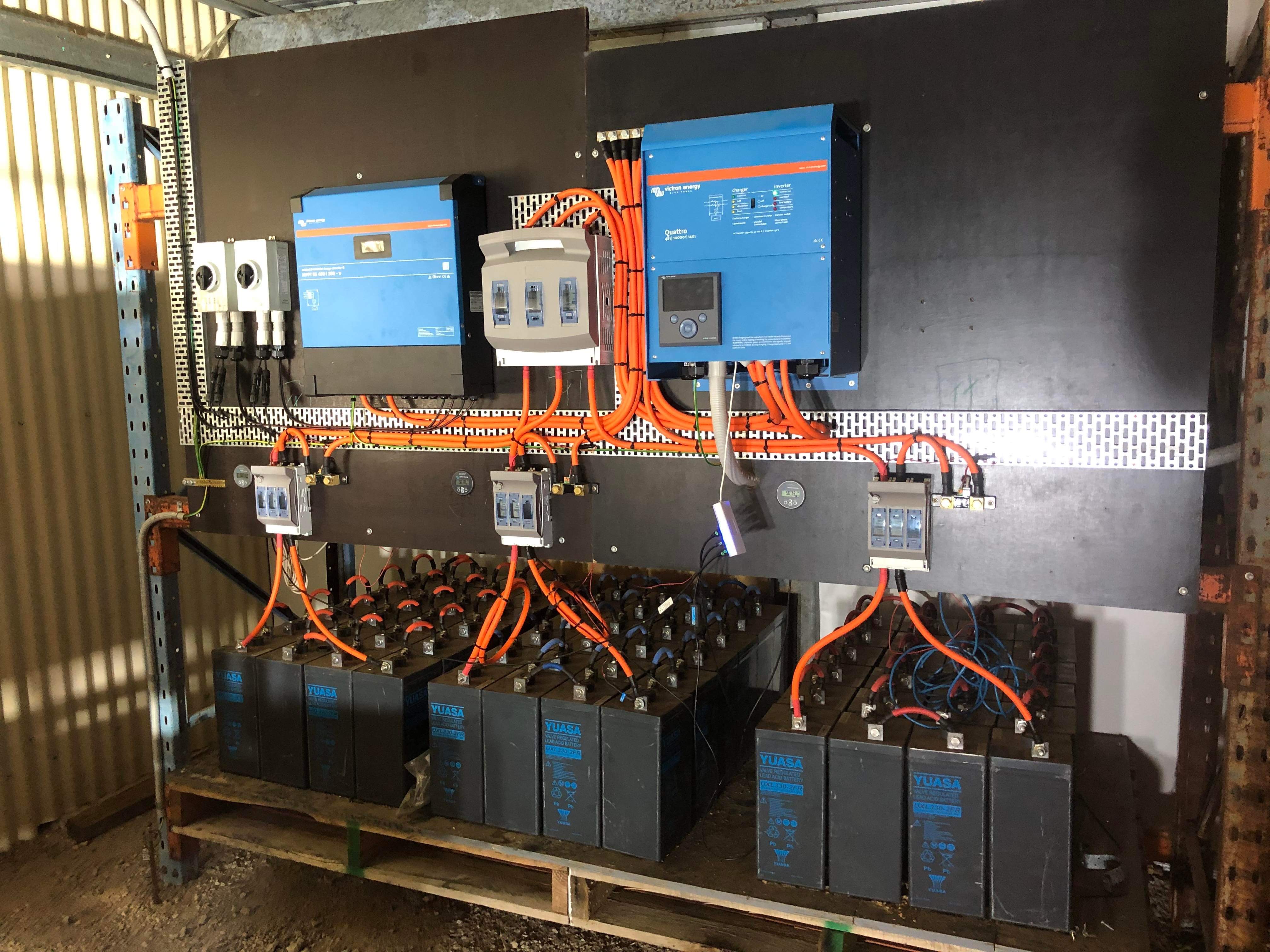
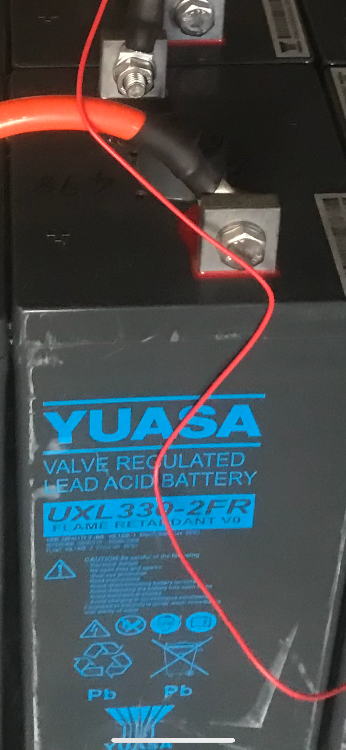
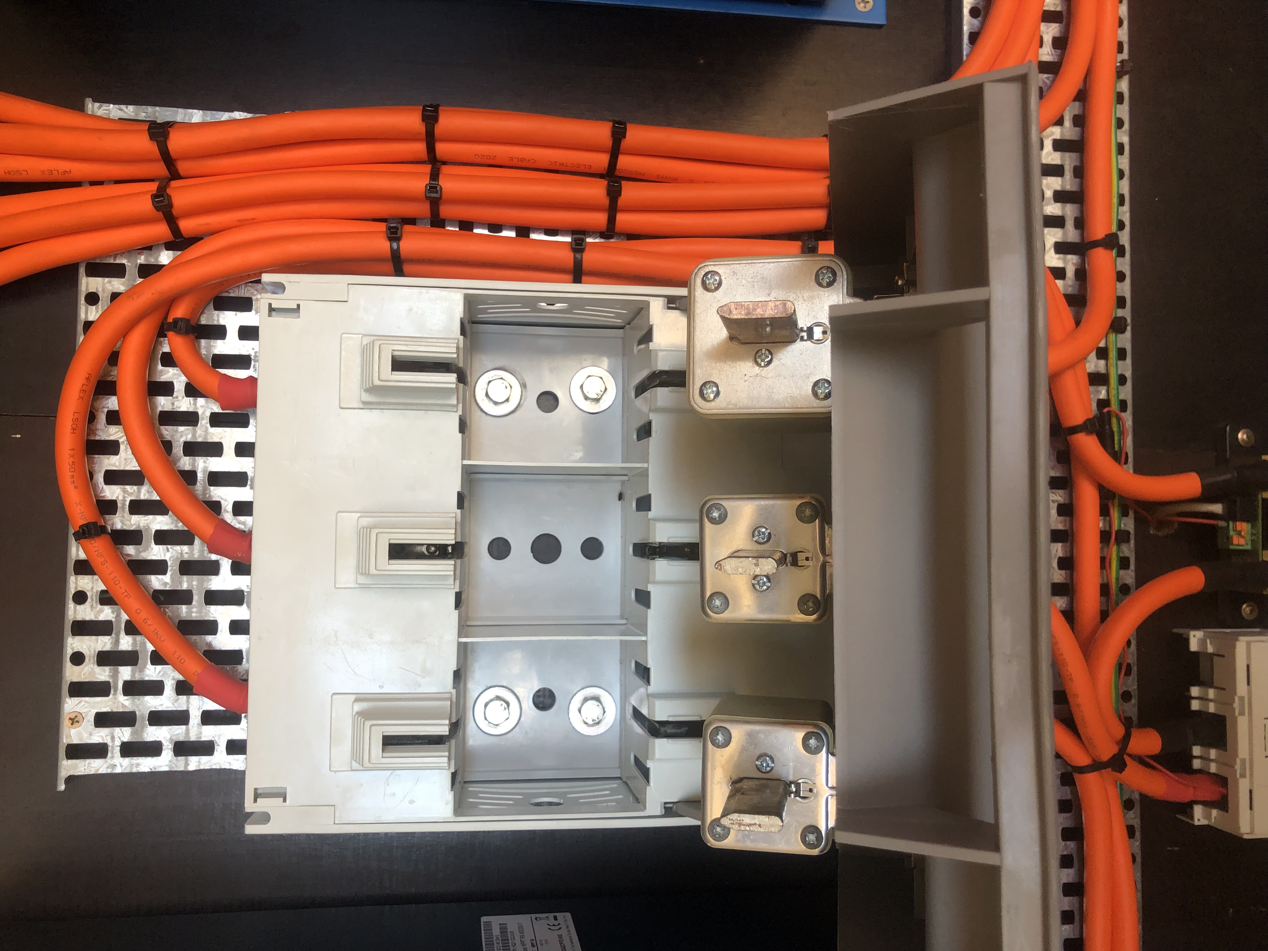
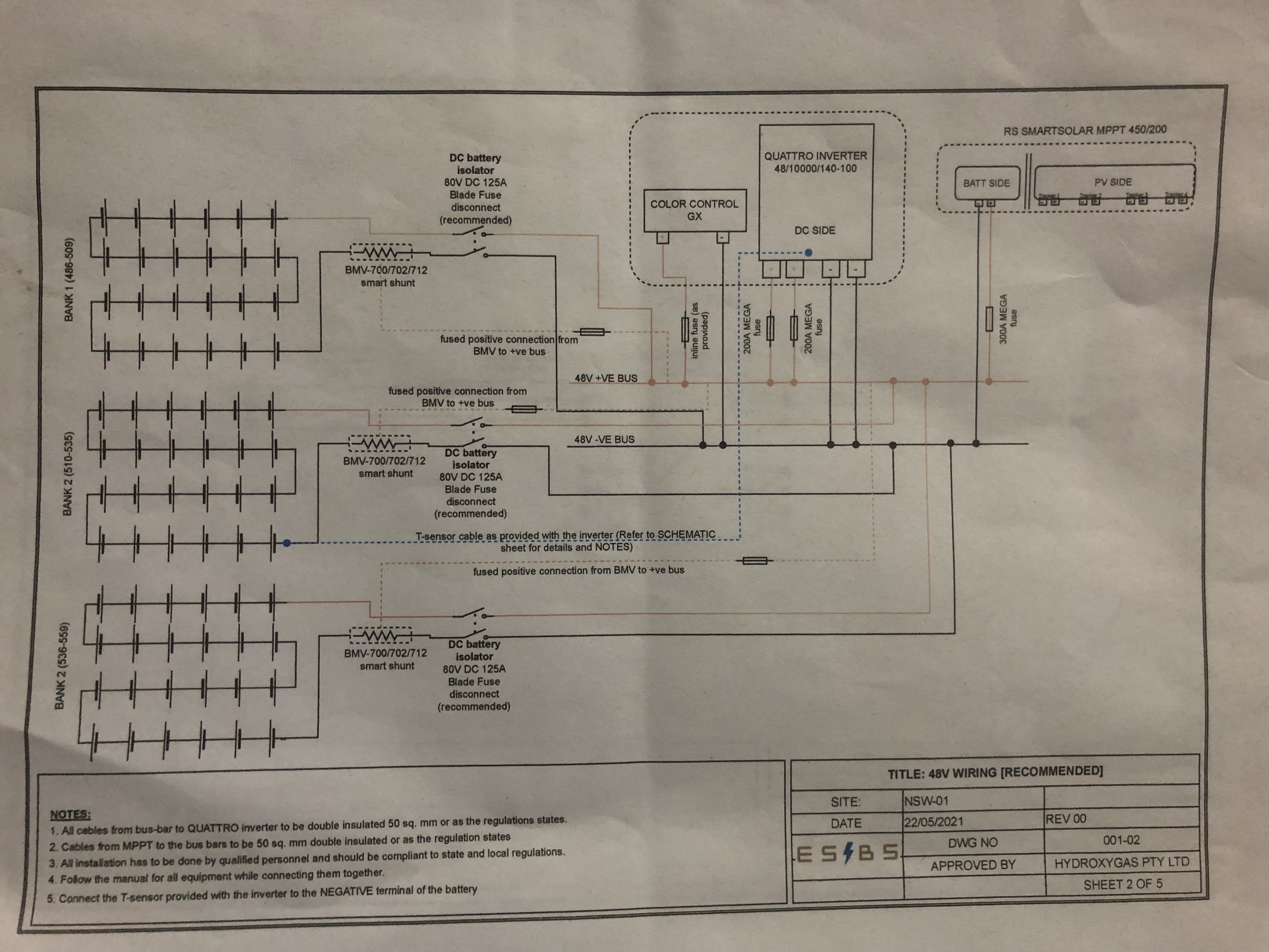
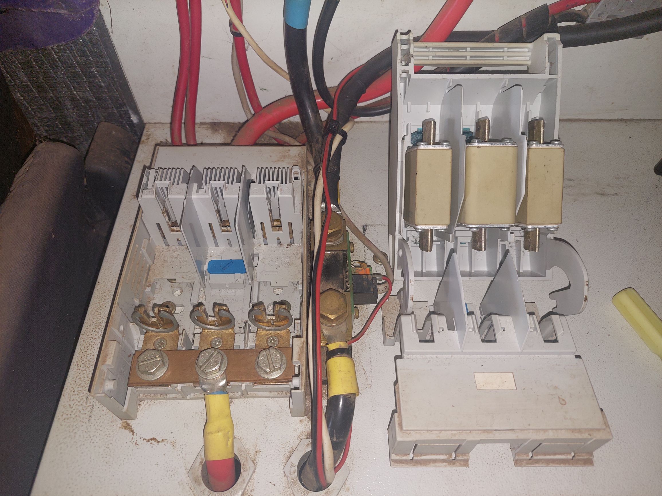
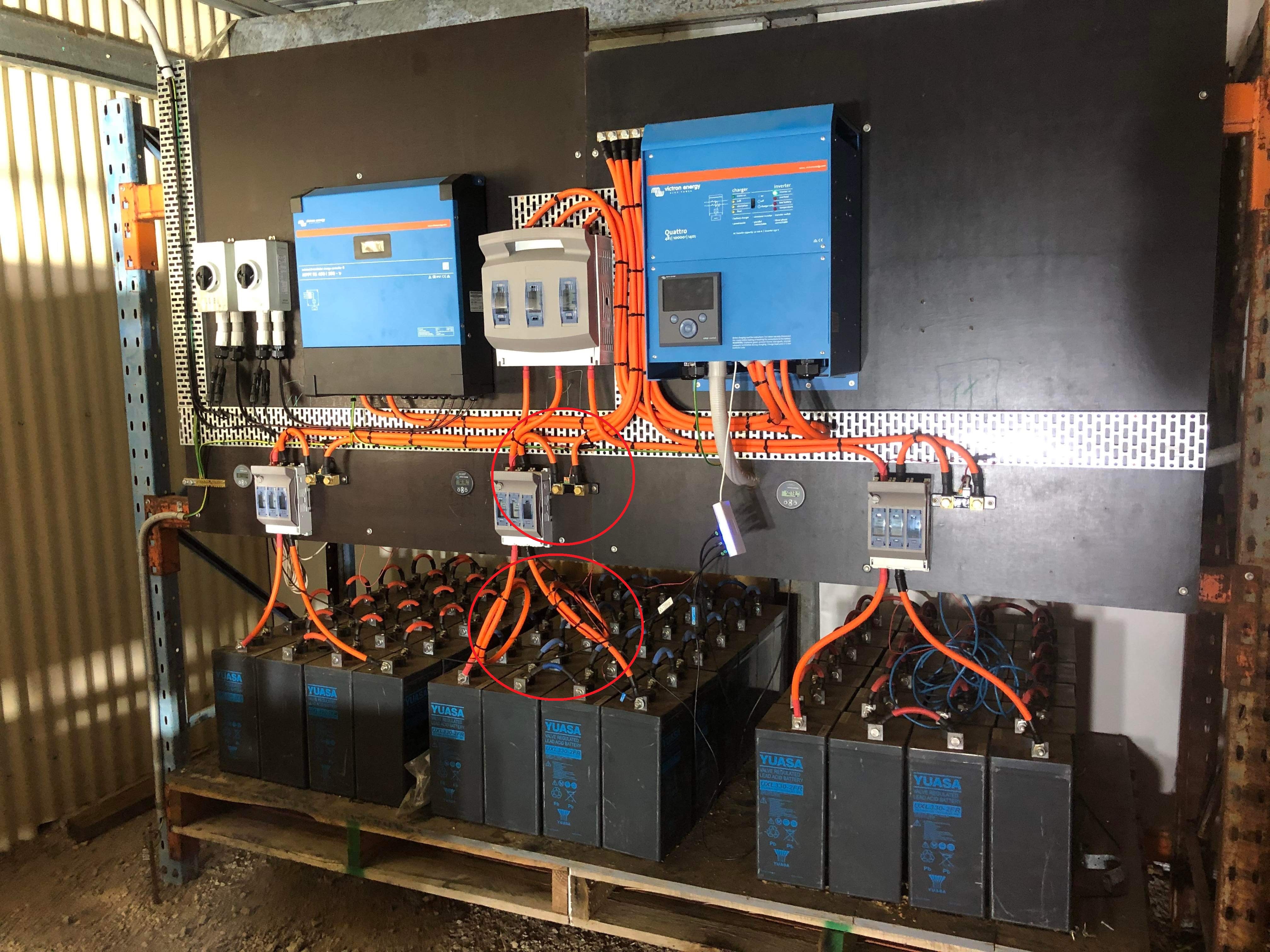
I have a 48v Quattro 10000 140amp with 3 battery banks of 24 2v 330ah Yuasa lead acid.
Stand a lone System

the middle bank is low.
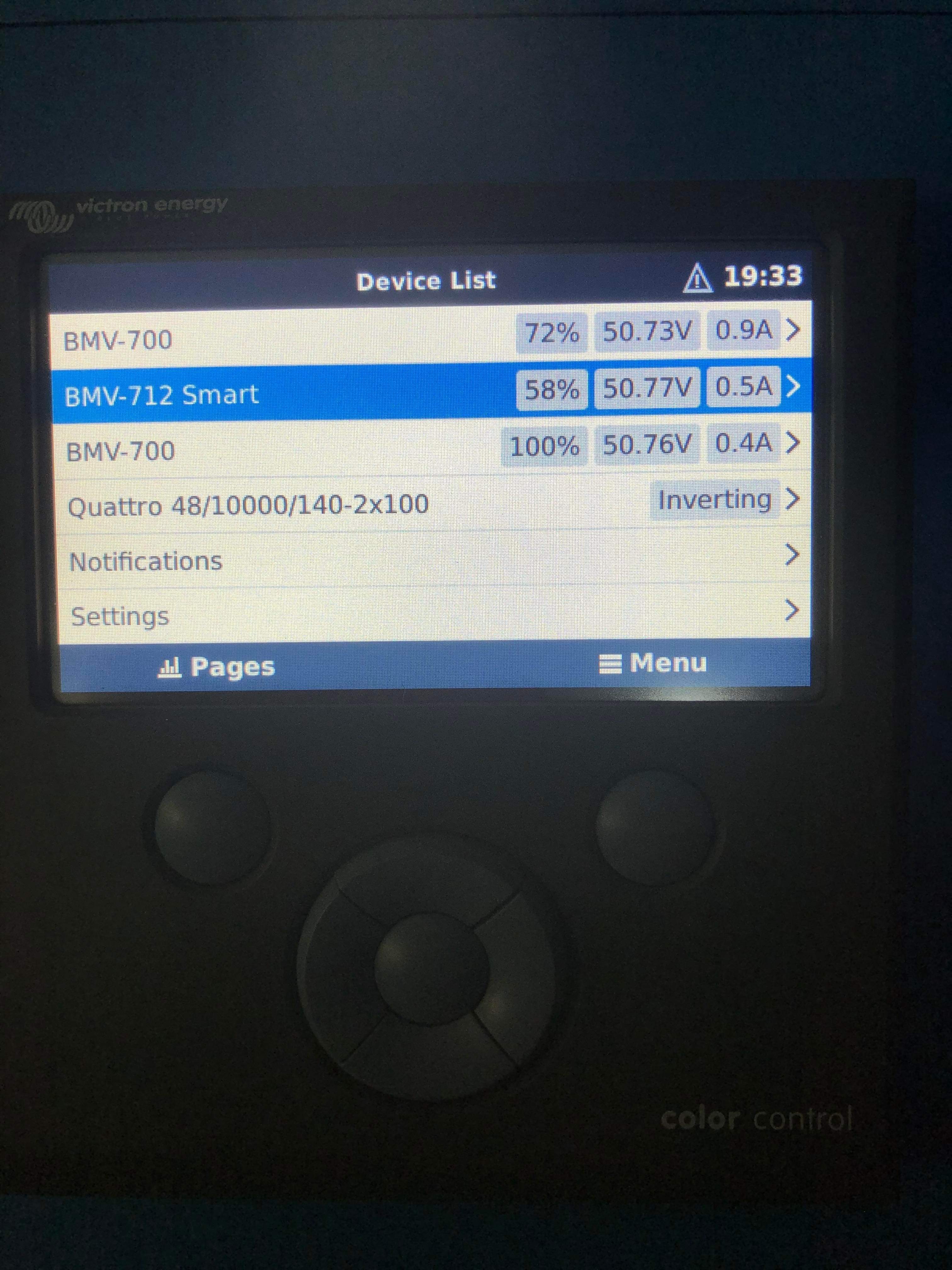
when connected all battery’s where at 100% charge.

lillte over 2 months latter

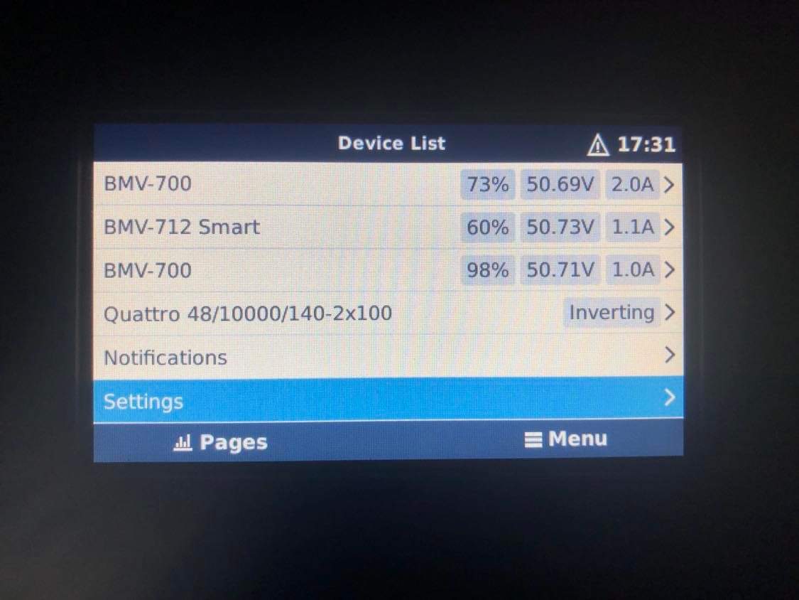
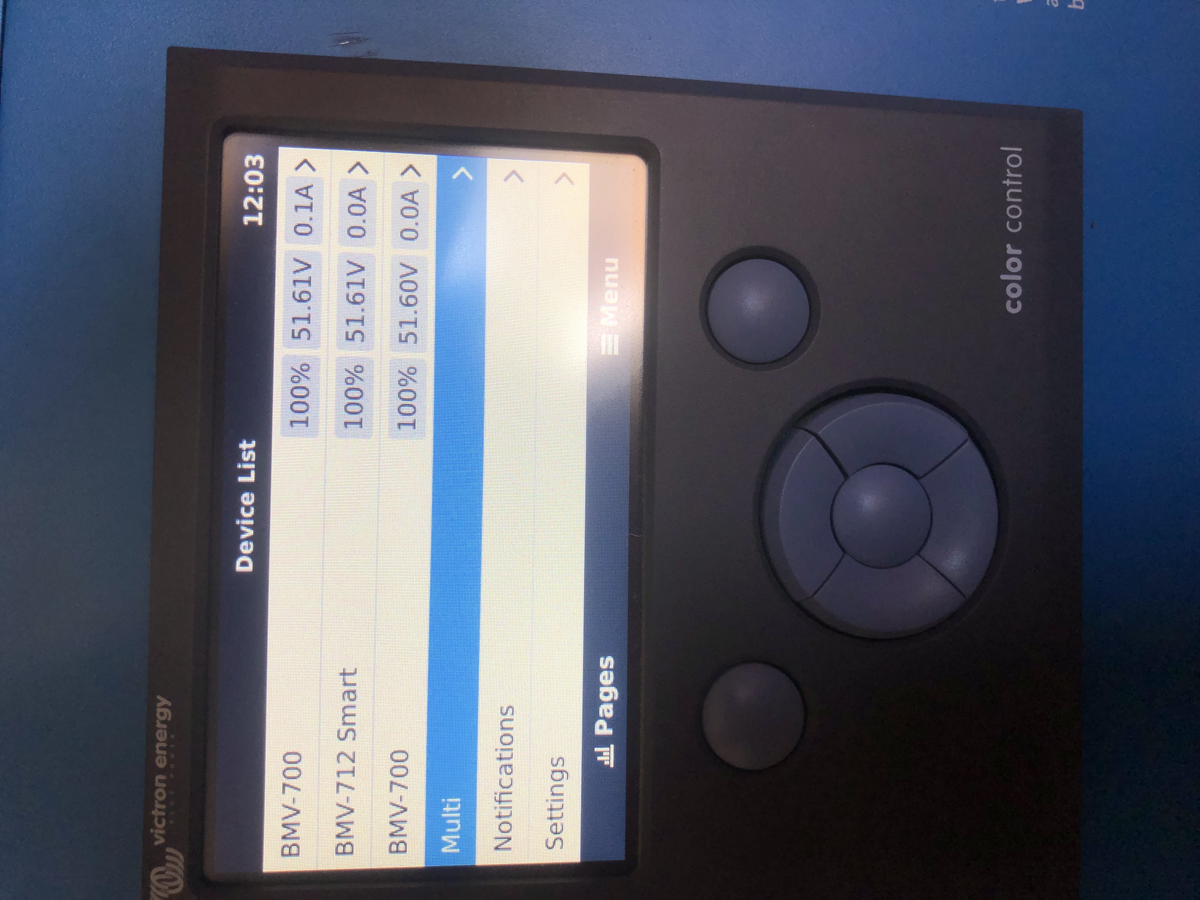
bank 1 is 98% bank 2 is 54% bank 3 76%

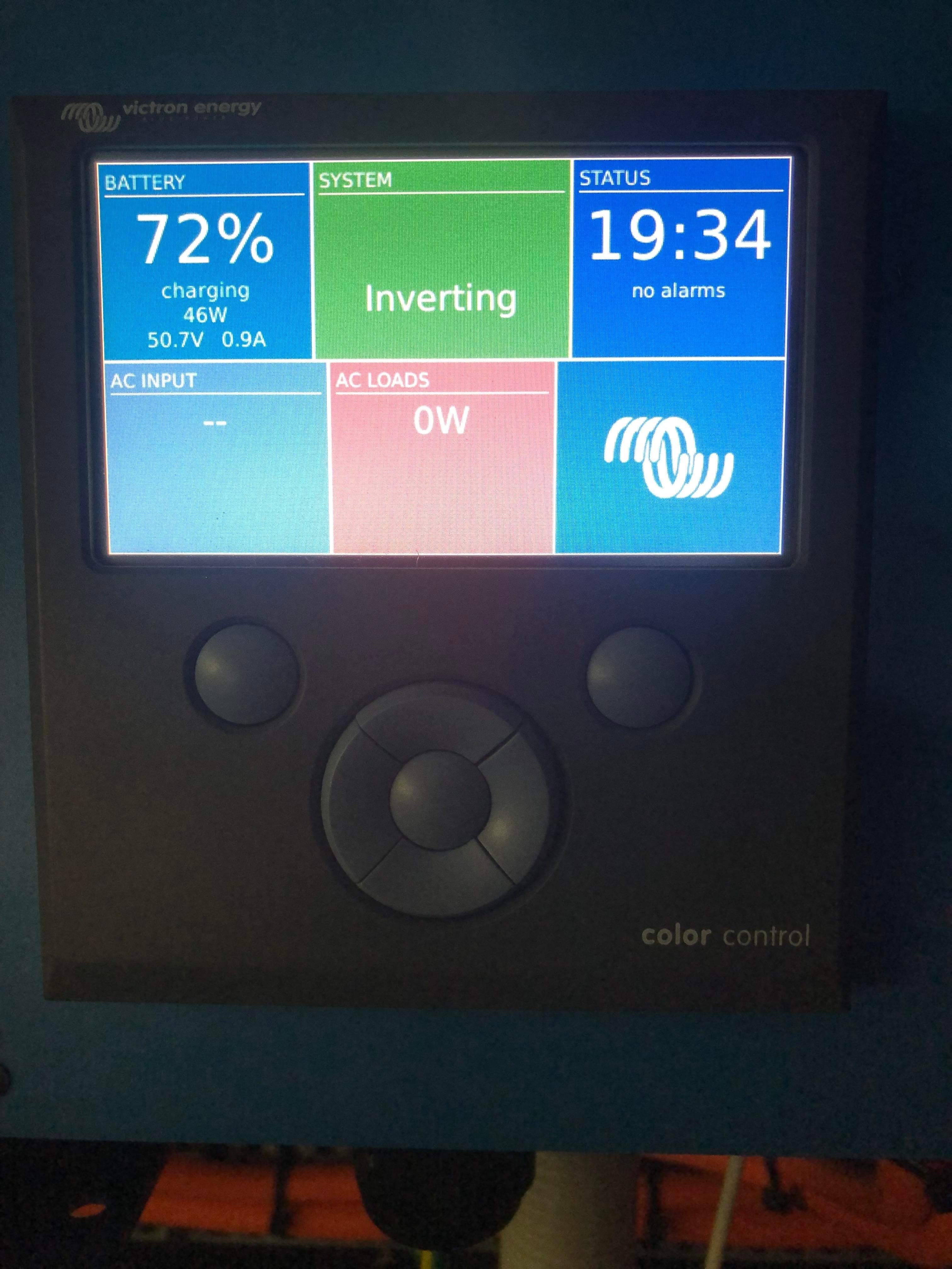
on the display the whole system says it’s at 75%

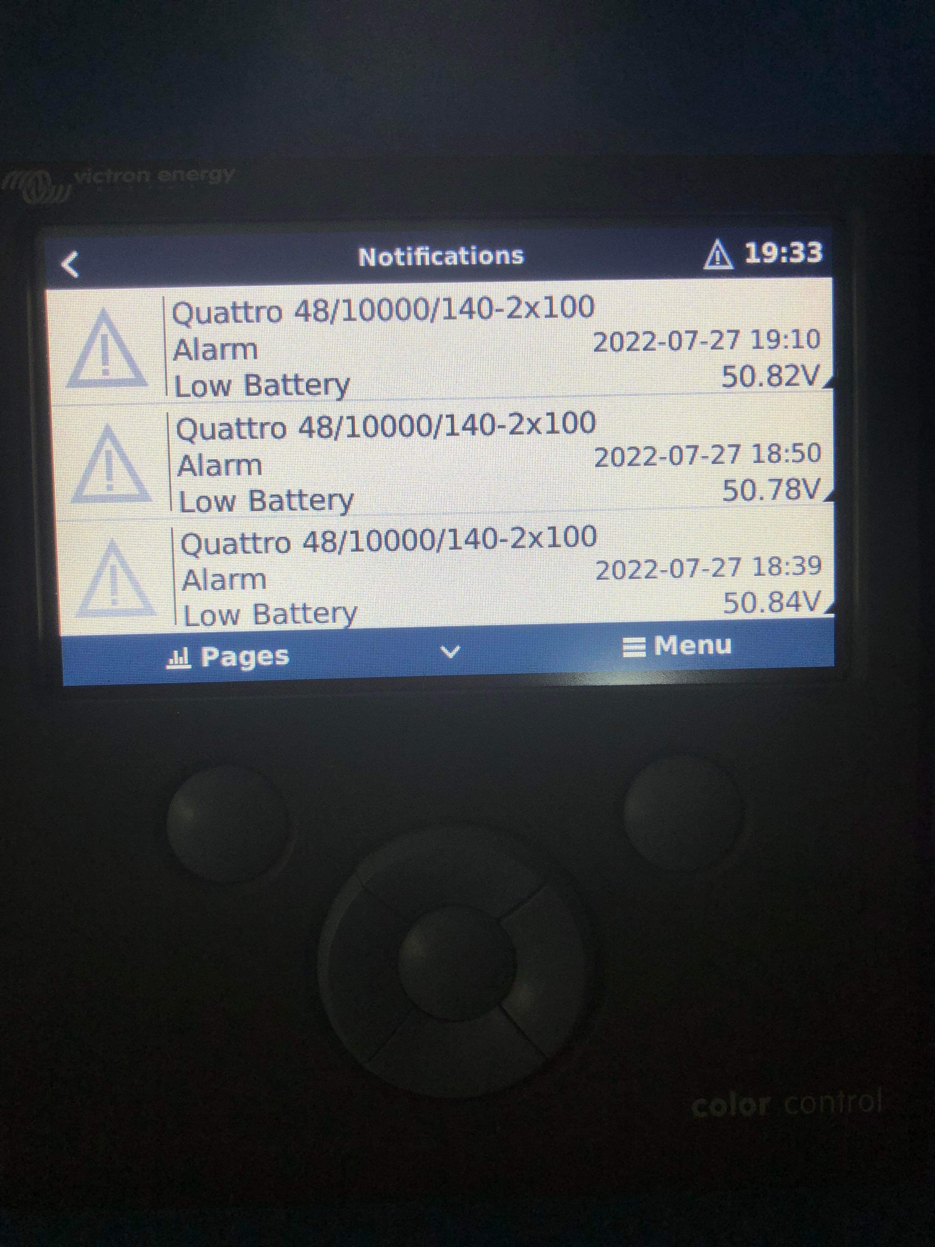
I had 19 low battery alarms last night.

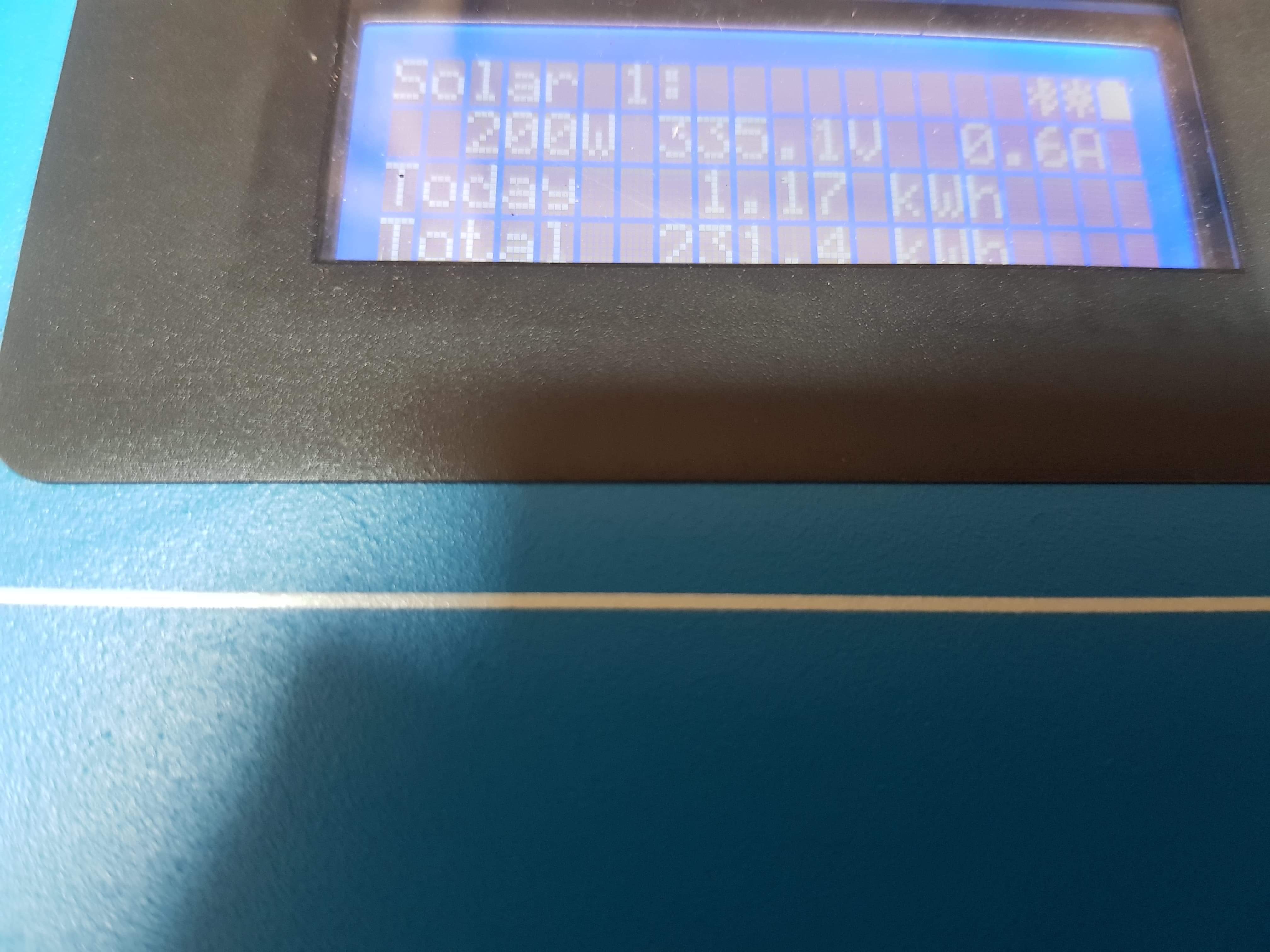
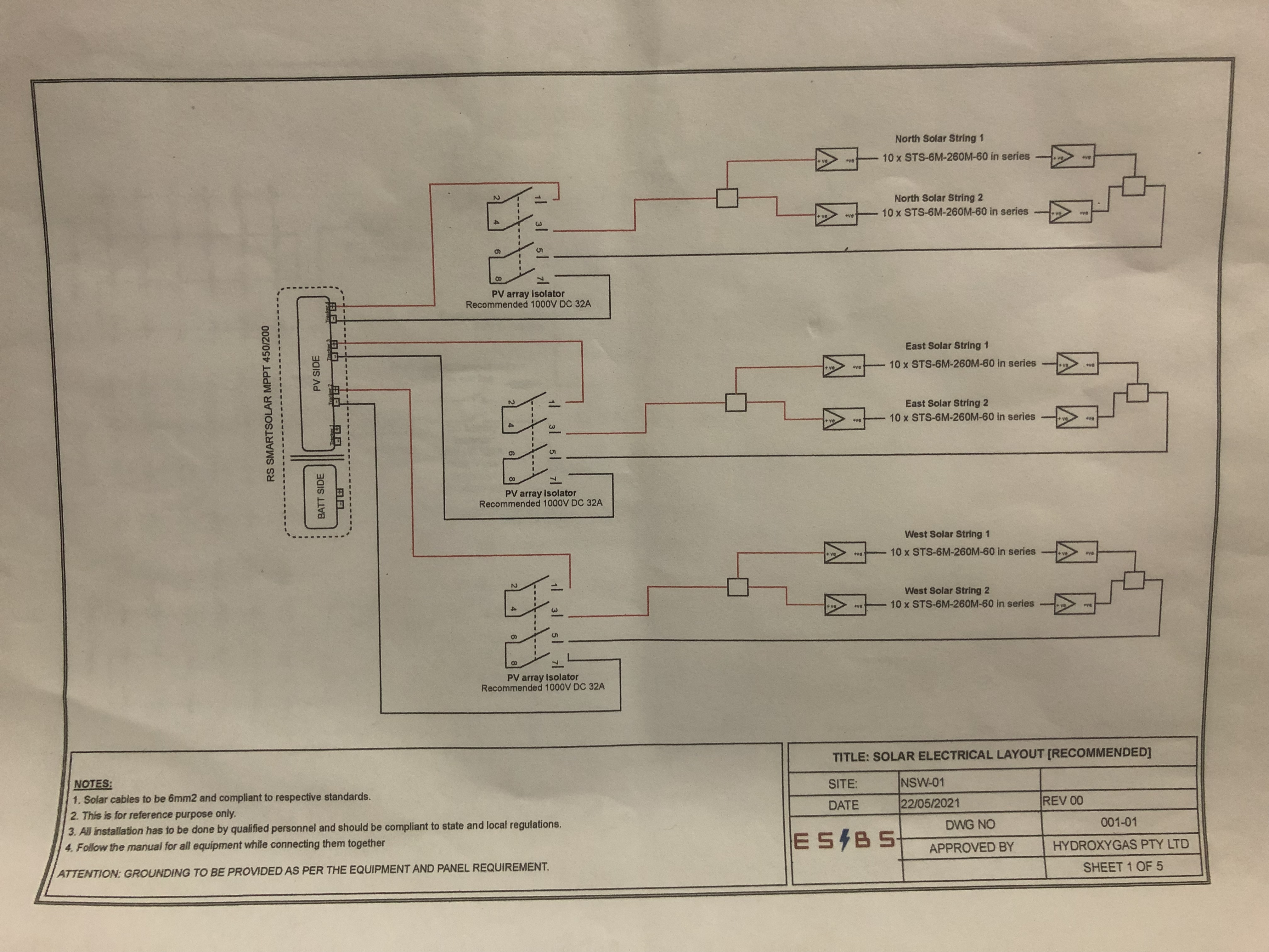
I have 40 250w 30.4v (Vmp) 8.24 a (Imp)

20 panels on each string.

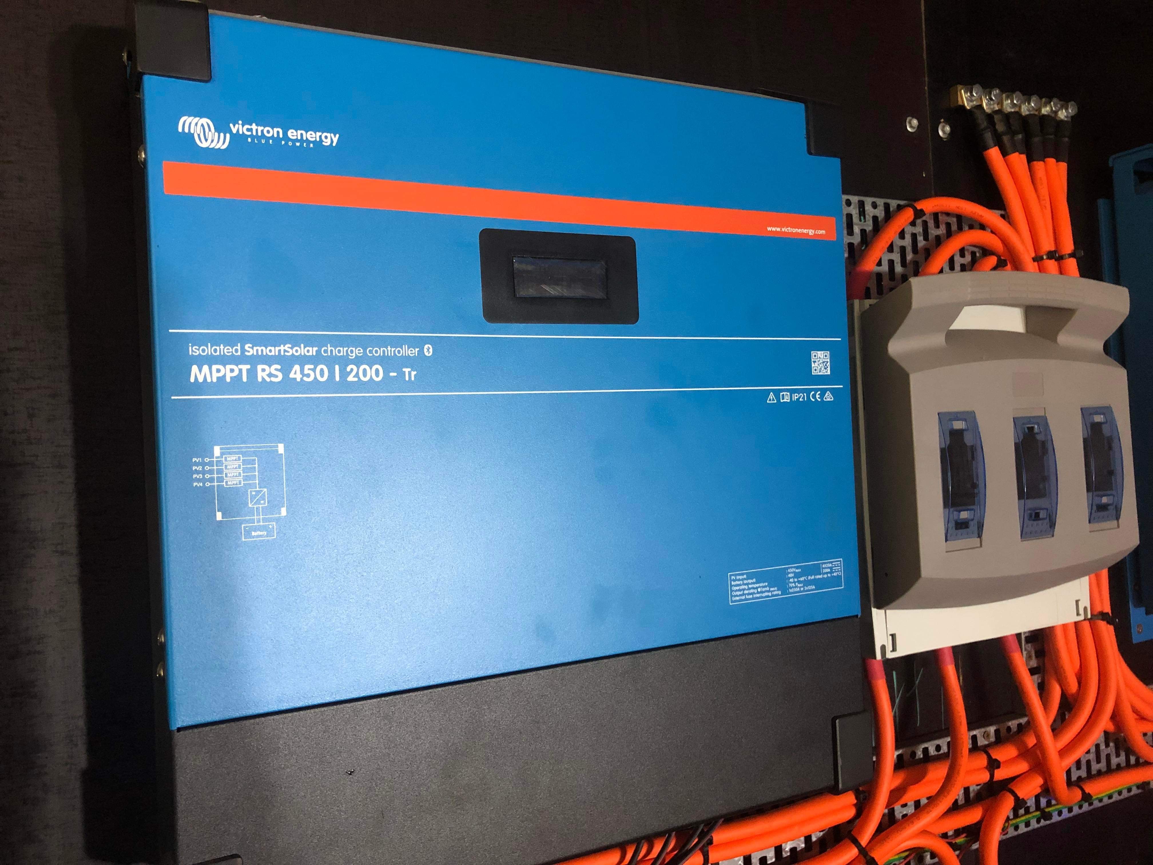
I have only seen the system charging once.

the charger is always saying idle,


my question is how do I get it to charge the bank 2

how can I set it up to use power from the panels 1st.

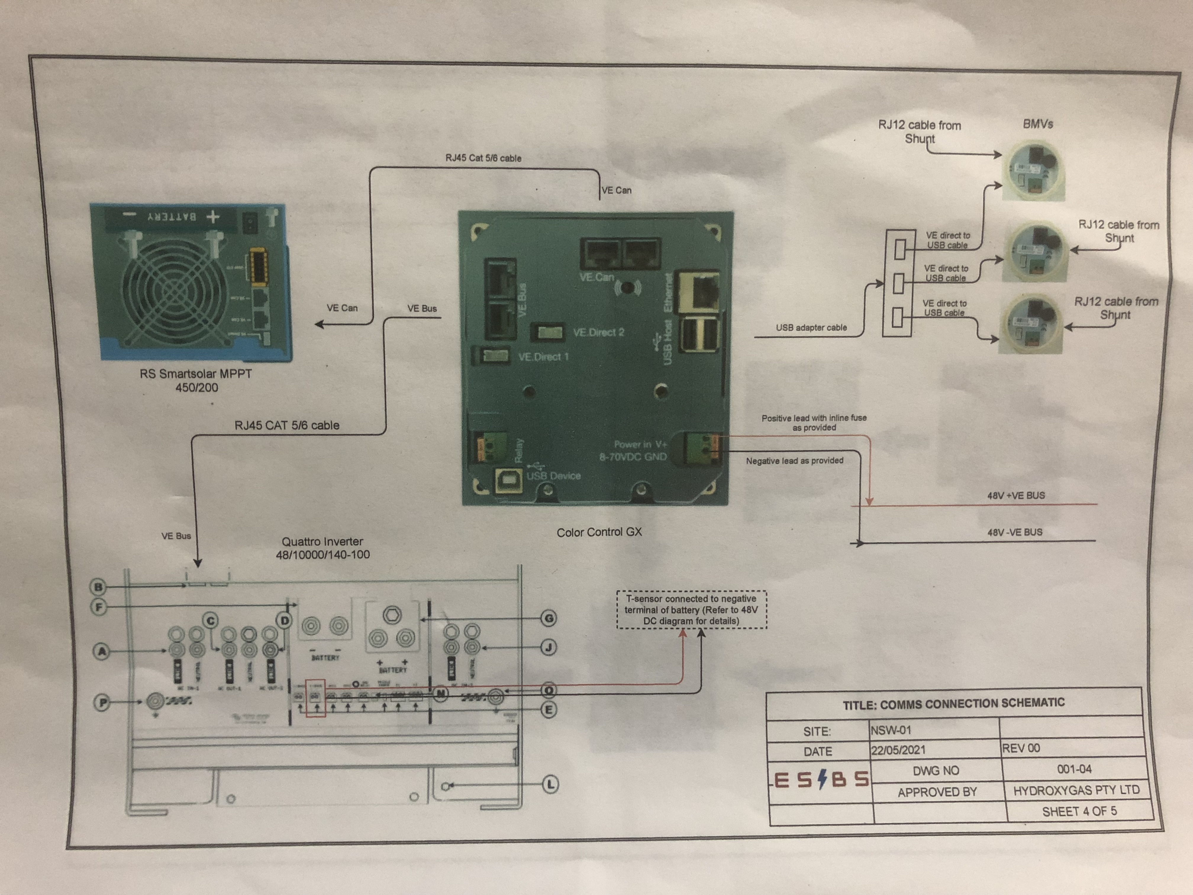
I’m not sure that the charger and the Q48 have been configured to each other yet..

we are about to move in to our house but want to make sure it’s all working 1st.

the business i brought it from hasn’t responded to my or my electricians messages and calls.

Thanks

Scottty

battery charginglow power
1 comment
2 |3000

Up to 8 attachments (including images) can be used with a maximum of 190.8 MiB each and 286.6 MiB total.

Alexandra avatar image Alexandra ♦ commented ·
@Scottty

How are they connected. Some pictures will help.

Is there a gx? Is there grid for charging?

0 Likes 0 ·
8 Answers
scottty avatar image
scottty answered ·

@Alexandra

please see photos.
not sure what a GX is.

I have 40 solar panels up for charging.

if there is any more required in please ask, I will do my best to answer.

Thanks

Scottty.4e2d98f3-22e5-4f21-8bb8-2668c4ac81cb.jpeg

d92fe397-3a5a-49f3-9a91-f4cbeeefcfd6.jpeg

d6c723ae-461b-4aca-91ad-76426e769428.jpeg

7aac0f41-6bf3-4dc3-981f-d627c9fd19fe.jpeg

3fd4f7ae-634c-4c32-a9b9-456308b046f1.jpeg


12 comments
2 |3000

Up to 8 attachments (including images) can be used with a maximum of 190.8 MiB each and 286.6 MiB total.

Alexandra avatar image Alexandra ♦ commented ·

@Scottty

I think your BMVs are talking nonsense. The 100% at 50v is not possible. And they are all the same voltage so most likely at the same state of charge.

I can see there are no loads on the system, does the mppt (solar) charge or produce any power?

How handy are you with a digital meter?

The manual for the mppt is here. It can be connected to by bluetooth so easy to check settings there. The battery charge voltages will possibly be on the side of the battery somewhere.

0 Likes 0 ·
scottty avatar image scottty Alexandra ♦ commented ·

@Alexandra

we are not living at the house yet. So everything is switched off.
mppt power to the house or battery’s. Not sure.
please see photo for one string.

i can be with the right advice. What would you like me to do with the Digital meter.

04487045-5c9f-4f6f-965d-2589fd26b218.jpeg

0 Likes 0 ·
Alexandra avatar image Alexandra ♦ scottty commented ·
@Scottty

I can see from that picture, no charging is happening. 0.6A and there really should be.

And the system is not at float voltage I would expect that to be closer to 53V or 54V. Possibly higher. You will need to learn what batteries they are and check settings for all the components.

Is the system online?

0 Likes 0 ·
scottty avatar image scottty Alexandra ♦ commented ·

No its not.

I my be able to though my phone.
or I can share my screen when logged in with you.

here is a pick of battery’s. Sorry I thought I added them already.

3b8ee09a-2027-47c2-8a37-cc37c049a0e9.png

0 Likes 0 ·
marekp avatar image marekp commented ·

@Scottty

Did your installer explained to you why you have 3 separately measured 48V battery banks instead ONE big battery?

I have a hard time seeing logic in it.

Also, from the safety stand point, the LA batteries should not be placed right under the inverters.

0 Likes 0 ·
scottty avatar image scottty marekp commented ·
Hi Marekp,

no he didn’t.

I brought the system from a business in Melbourne and had an installer local to me install.


0 Likes 0 ·
Alexandra avatar image Alexandra ♦ marekp commented ·

@MarekP

Sometimes it is good to keep an eye on each "battery" separately.

See then like Pylontecs a few in a stack (in this case 3). Each "battery" has its own state of charge. In this case we dont know who the master is. I would wonder if it is the 712 smart?


0 Likes 0 ·
marekp avatar image marekp Alexandra ♦ commented ·

@Alexandra

I have never seen the LA batteries used this way.

Pylontecs are Lithium so it is better to have each cell under control by BMS and the information about SOC of all separate battery units is sent to the charger on one CAN wire.

Here we have three different values of reported SOC and charger is either confused what to do with them or simply ignores two of them. Either way is not healthy for the battery.

As for which BMV is a master, look at the percentage values on each BMV and what GX is reporting as a SOC. Looks like the first BMV-700 shows the 72% reported by GX as a SOC.

If the SOC 100% was correct for one of the batteries than system would still charge this battery as it had 72% SOC and overcharge it.

This is why I do not see the logic in such arrangement.

0 Likes 0 ·
Alexandra avatar image Alexandra ♦ marekp commented ·

@MarekP

It is certainly an interesting setup. It is better for monitoring to see each bank separately.

I guess they did not want to spring for a fourth one as the main one for the entire bank to set as the one for the entire system, that would have been a bit more logical.

But for checking current sharing and checking performance the separate ones make sense.

All if this system is an unknown to the OP unlike yours, you who knows every wire there.

0 Likes 0 ·
marekp avatar image marekp Alexandra ♦ commented ·
@Alexandra

I would make one battery out of 72 cells (4p24s) and use only one BMV. It would be simpler and safer for the battery.

Also OP would not get confused what to do if one battery fuse gets blown. What to do later with that battery? how to bring it to the same SOC like the other two.

0 Likes 0 ·
Alexandra avatar image Alexandra ♦ marekp commented ·
@MarekP

I see your point.

Bank maintenance would still need to happen. The choice is to shut down the whole system and do it or part. As klim8skeptic mentioned. An interesting design and choice of setup.

OP will be checking and re -commissioning his system by the end of everything if there is no help from previous owner or installer.

0 Likes 0 ·
scottty avatar image scottty marekp commented ·

This is an earlier photo I took.


they are changing but not equal.

but not draining the same.

1f261140-87a9-4c50-b354-f3e6b3926568.jpeg

0 Likes 0 ·
klim8skeptic avatar image
klim8skeptic answered ·

Dunno what to think about the Yuasa 330 UXL charging specs ~ 30a?

It is a bit odd that only 2 of the 4 mppt inputs have been used. Maybe for the best, given the above.

A neat enough install, but some odd purchasing, design, install decisions have been made.

1 comment
2 |3000

Up to 8 attachments (including images) can be used with a maximum of 190.8 MiB each and 286.6 MiB total.

scottty avatar image scottty commented ·
There is another 20 panels to come on. And a wind turbine, this is why only two are been used for the moment.


install was done to design by the other guy.
installer has been trying to contact designer but he won’t answer.

might have to scrap it and start again.

0 Likes 0 ·
klim8skeptic avatar image
klim8skeptic answered ·

Looking at the upper fuse/breaker, I can see 3 batteries coming in from the bottom, and at the top 1 cable going to the mppt, and 2 cables going to the quattro.

Where is the bus that ties these 3 positive circuits together?

Photo of connections.


7 comments
2 |3000

Up to 8 attachments (including images) can be used with a maximum of 190.8 MiB each and 286.6 MiB total.

klim8skeptic avatar image klim8skeptic ♦ commented ·

Mppt does not seem to be connected to CCGX. device list.

0 Likes 0 ·
marekp avatar image marekp klim8skeptic ♦ commented ·
@klim8skeptic

Maybe is on the top of the list and we are seeing only bottom part.

0 Likes 0 ·
scottty avatar image scottty marekp commented ·

@klim8skeptic @MarekP

I will get photos of the whole screen tomorrow.

0 Likes 0 ·
klim8skeptic avatar image klim8skeptic ♦ scottty commented ·

There are no comms cables going between the mppt, and ccgx.


Open up the upper fuse holder and take a pic once the cover/fuses have been removed.

It would probably be best to power everything down before yanking the handle..

0 Likes 0 ·
scottty avatar image scottty klim8skeptic ♦ commented ·

Here are you requested photos.

bc5a9f5a-6dff-449a-af5c-7a200a62bf6f.jpeg

system was still at see photo

1a4d833b-59e7-44c3-a65c-74a059731b2b.jpeg
then after I opened all the breakers now it says all the battery’s are at 100%

a0ba334d-67af-47f3-9b58-f0fa66a72e2b.jpeg
I have turned the system off. As I don’t trust it.
I will have to do a test on each bank to see when they come back as.

but here is the the wiring diagram that was sent with the system.

e7bcdf39-ee17-402a-b4a9-6336dd18477f.jpeg

c769b67b-ee18-4fbd-a936-56e807da22ea.jpeg

aa6f9db8-c0b2-492e-93de-f4f7a1a19fec.jpeg

hope this helps.

yes there is 2 banks (left & Centure) that go to the inverter and one that goes to the charger.

0 Likes 0 ·
klim8skeptic avatar image klim8skeptic ♦ scottty commented ·

Only 1 photo came through.

I suspect that the fuse disconnect has been modified somewhat similar to this.

20220731-1100091.jpg


0 Likes 0 ·
20220731-1100091.jpg (591.2 KiB)
scottty avatar image scottty klim8skeptic ♦ commented ·

Sorry I did an edit.


f13afda4-6884-4a6c-89c7-37150e4b0ae7.jpeg

not sure if it’s the same. I will see if I can pull the cover off.

other photos where:

after disconnecting now it says it’s all at 100% I don’t trust it.

before

e57997d4-bc68-4e8e-9629-58fdc42fbed4.jpeg

after

61c67f76-03ca-41a8-882d-767c3add4645.jpeg

and the wiring diagram that we received with the system

a21bdc11-00f3-456a-980b-824cf96614eb.jpeg

eafbc115-c005-4244-af46-d9d3aab89534.jpeg

3b16f3e9-d727-45f2-a46a-bda59e78039f.jpeg

0 Likes 0 ·
jens-due avatar image
jens-due answered ·

It looks like if you follow the cable from the plus on the Mppt that it goes through the left of the three large fuses and down to the left set of batteries

2 comments
2 |3000

Up to 8 attachments (including images) can be used with a maximum of 190.8 MiB each and 286.6 MiB total.

nhuillard avatar image nhuillard commented ·
My guess is that there is a busbar between the upper connections in the main/huge breaker. To be verified by OP.

Cable length and current path is not uniform though...


0 Likes 0 ·
scottty avatar image scottty nhuillard commented ·
No sure. Is there anywhere you would like a closer photo of?
0 Likes 0 ·
netrange avatar image
netrange answered ·

The middle bank has a different derivation from the shunt than the others.
Overall, the lengths are the same, but the measurement could be influenced.
Optically it looks really good but the cable lengths between battery, shunt and system should all be the same length so that all shunts have the same "minus length".
36878-4e2d98f3-22e5-4f21-8bb8-2668c4ac81cb.jpeg


1 comment
2 |3000

Up to 8 attachments (including images) can be used with a maximum of 190.8 MiB each and 286.6 MiB total.

scottty avatar image scottty commented ·
I agree
0 Likes 0 ·
Paul B avatar image
Paul B answered ·

Maybe consider the below.

Bring all he battery negatives to one new neg busbar then use one shunt and go from the shunt load to the inverters (may need a new 1000 amp shunt). The batteries will self level out. this way you measure everything as one bank. and there is only one SOC and readings to consider. also you will need to do equalize once every 2 to 6 mths.

once the batteries die then replace them with lithiums. and then as there will be a BMS make sure its one large bank with one BMS.


2 |3000

Up to 8 attachments (including images) can be used with a maximum of 190.8 MiB each and 286.6 MiB total.

klim8skeptic avatar image
klim8skeptic answered ·

Given how much is deficient with the OP's system, perhaps some advice on battery / mppt charging settings would be a good first problem to solve. Yuasa 330 UXL specs

The 330 UXL seem to be a battery that is used primarily as a backup, not a daily cycler. The specs show a float voltage of 2.23v/cell, but also an upper voltage of 2.4v/cell (all at 25c). That would equate as a bulk/absorb voltage of 57.6v, and a float voltage of 53.2v ??..

Can anyone comment on the temperature compensation figures??

EDIT. I think the temp C/O is 3mv/cell/tempC given the float voltage is listed as 2.25@20c and 2.22@30c


2 |3000

Up to 8 attachments (including images) can be used with a maximum of 190.8 MiB each and 286.6 MiB total.

netrange avatar image
netrange answered ·

According to the documents, the plant is from May 2021

How is sufficient balancing ensured ?


With a configuration of 18 cells in 3 parallel groups, the groups always discharge each other.
The system has now been in operation for just over 1 year.
You would have to measure all the cells individually and first put together a new individual bank so that the system runs again.
Each cell would have to be checked and charged if necessary.

Disassemble ... Measure ... Reassemble

Translated with www.DeepL.com/Translator (free version)

2 |3000

Up to 8 attachments (including images) can be used with a maximum of 190.8 MiB each and 286.6 MiB total.

Related Resources

Additional resources still need to be added for this topic

VictronConnect VE.Bus charging manual