question

shevronseven avatar image
shevronseven asked

Why is the load output on my MPPT not displaying the correct voltages?

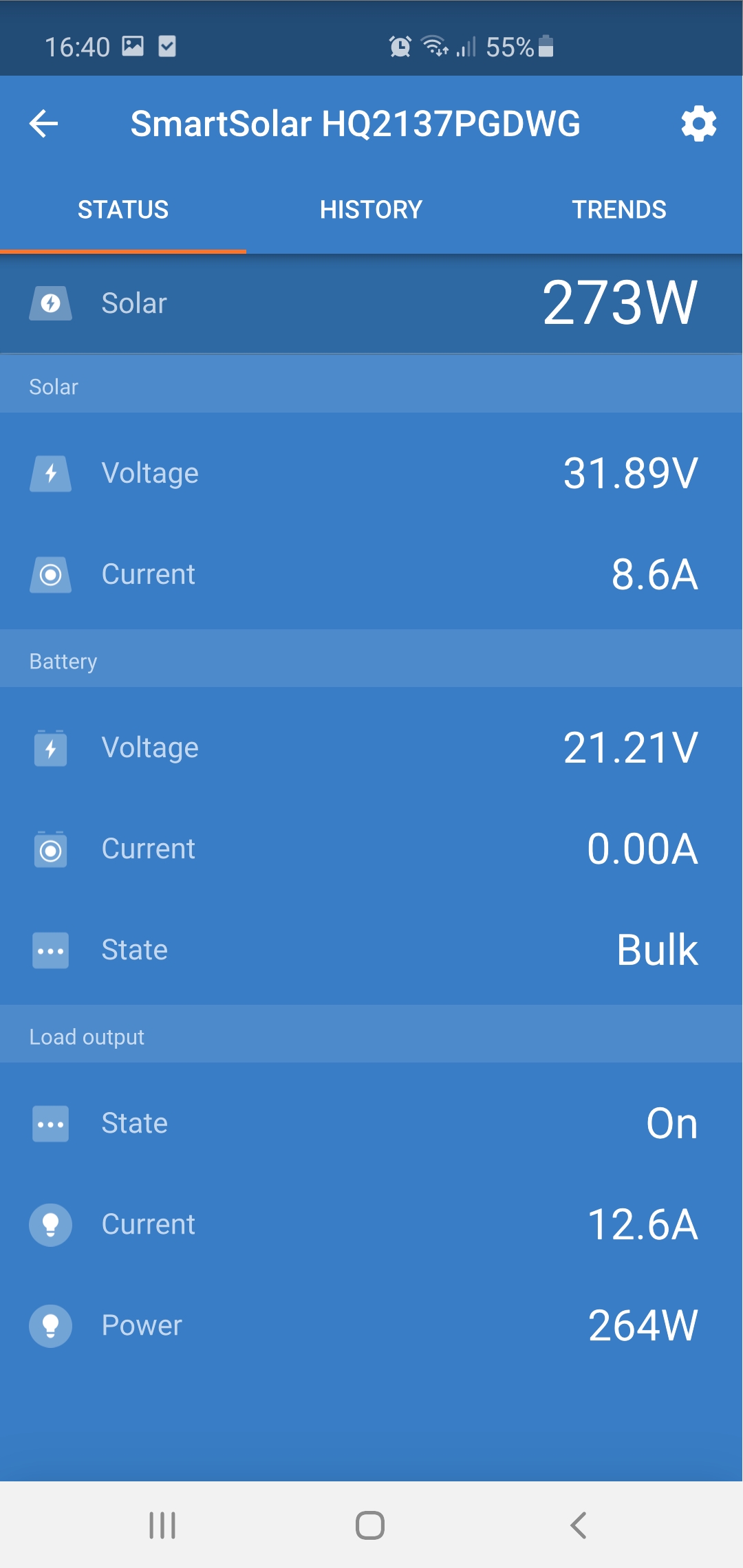
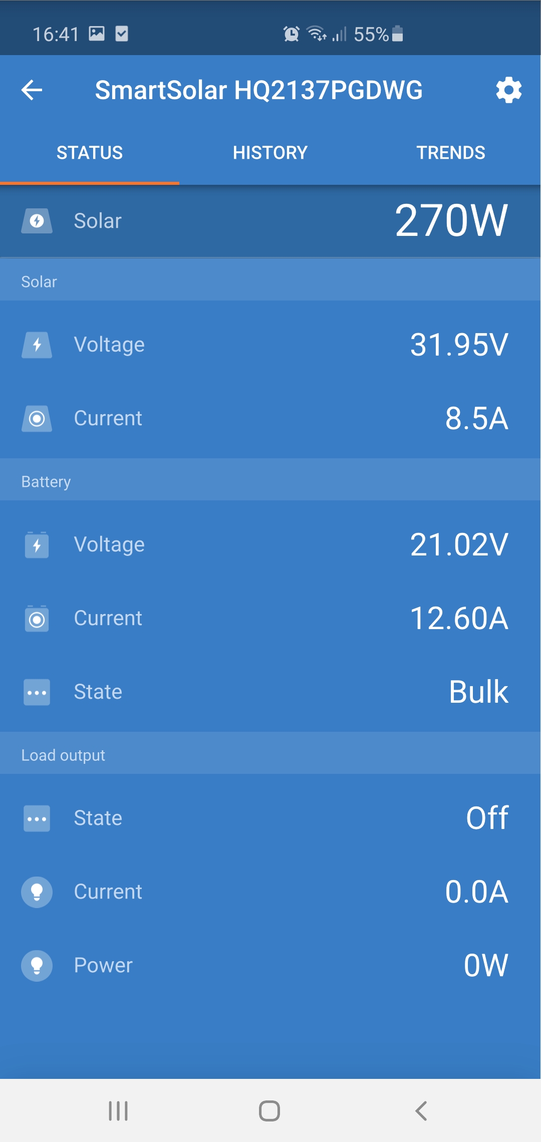
Yesterday I have recieved my MPPT 75/15 SSC controller. Connected it to my 375w PV panel (open 41.6V), 24 V battery, all the systems was working well, I tested load output on my car phone charger, again, averything was going perfect, software controlls of load output was also working (on/off). Then I upgraded load with 600W inverter, after flipping a switch the inverter turned on, but in the app, load output status turned to off, with 0 amp/watt flow at the same time. BUT! The load was energized, and amps where flowing, inverter was working. At the same time PV power increased to 120w and the charging current on the battery by 5 amps (positive increase, allthou it should go with the minus sign). Obviously load output mosfet was blown.

So the questions are.

1.Why you say that load output is short circuit proof, quote "The load output is short circuit proof" Victron energy, smart solar charge controllers (MPPT 75/15), manual, if it is clearly NOT short circuit proof?

2.Why is firmware programmed to ignor load shunt input when the load output is software disabled (in reality working), and display makeup values instead reporting fault or just showing real situation, and also dangerously impact other values like battery charge current?

Not sure - Admin please assign or create
2 |3000

Up to 8 attachments (including images) can be used with a maximum of 190.8 MiB each and 286.6 MiB total.

4 Answers
wkirby avatar image
wkirby answered ·

In the manual, it states not to connect inverters to the load output. Inverters present a complex reactive load to an upstream switch. The upstream switch in this case is the MOSFET in the load output.

The load output does have over current protection which will helps to make the device short circuit proof. Bear in mind a short circuit is an over current event, not an over Voltage event and there is no mention of the load output handling over Voltage events.
A reactive load could produce a very high Voltage when switch off. This is known as flyback Voltage and can be hundreds or even thousands of Volts for a very short period of time, but long enough to destroy semiconductors in the blink of an eye. It is common for inverters to exhibit this and that is why the advice is given in the manual to not connect inverters to the load output.

I don't think the device has been specifically programmed to make up dangerous fault values, it's more to do with the device being damaged and it no longer has the ability to read the current anymore.
Where accuracy isn't critical, it is common practice to use the resistance of the MOSFET channel when it is on as a shunt to measure the current going through it. This is known as the RDSon of a MOSFET and is fairly constant in a working MOSFET and so the Voltage drop over the channel can be used to measure current with a fairly reasonable accuracy. In a melted MOSFET the channel resistance is likely to be extremely close to zero Ohms and so current measurements would also evaluate to zero Amps.
The high Voltage may have also continued is path of destruction further on.

So the answers are:
1) The load output does handle short circuit or over current events, but not over Voltage (flyback) events. In your case I suspect that the unit faithfully responded to an over current event caused by the inrush current to the inverter and switched the load output off which in turn produced a very high flyback Voltage from the inverter and destroyed the MOSFET which drives the load output. The failure mode of the MOSFET was most likely a melted silicon die. All three pins are now melted together and are all short circuited to one another. Drain and Source, the pins over which the current is measured are now reading as close to zero Ohms as practically measurable.

2) Given the likely failure mode of the MOSFET in its short circuit condition a shunt of what is now close to zero Ohms is not going to have a very high Voltage drove over it and so the microcontroller would only measure what is there. If it doesn't measure a Voltage then it would presume there is not current flowing as expected. It does not know that the shunt is melted.
So the firmware is working as expected, it has responded to the over current event and turned the MOSFET off, it shows that it has done so. It can't measure any current because the shunt has gone short circuit and so it shows zero Amps.
Now, even if the MOSFET has blown open circuit, no current flowing through it still, there is still no shunt to measure over. In this scenario the microcontroller would see full scale Voltage for the shunt measurement. This is also an expected scenario when the load output is switched off because the MOSFET channel resistance would be very high. It would need to be programmed to ignore this very high reading as unrealistic, especially when it has instructed the MOSFET to be off.
So if the microcontroller reads full scale at its ADC input and the load output has been driven off, then it would make sense that it reads zero Amps.
It's very unlikely that the microcontroller has an input to detect that the MOSFET has been destroyed.

Basically, it you use the device otherwise as instructed and it ends up getting damaged, then it would be expected that it gives erroneous readings and acts strangely if at all.

2 comments
2 |3000

Up to 8 attachments (including images) can be used with a maximum of 190.8 MiB each and 286.6 MiB total.

shevronseven avatar image shevronseven commented ·
Like your answer mate!

I will set the system up just to get some screens for the argument. I know that the firmware is at faut, because the load output shunt IS working! When you perform a reset, it puts the load output to on, and it's able to use load shunt to display the load (W) value, but when you put soft to allways off, it does show off, then load current is displayed as 0 BUT! Charge current increases by the same amount as the load current.

1 Like 1 ·
wkirby avatar image wkirby ♦♦ shevronseven commented ·
Screen shots would be cool, thank you.
0 Likes 0 ·
klim8skeptic avatar image
klim8skeptic answered ·

1.Why you say that load output is short circuit proof, quote "The load output is short circuit proof" Victron energy, smart solar charge controllers (MPPT 75/15), manual, if it is clearly NOT short circuit proof?

Perhaps you could share a pic/screenshot with the above specs??

The manual, https://www.victronenergy.com/media/pg/Manual_SmartSolar_MPPT_75-10_up_to_100-20/en/technical-specifications.html#UUID-76446d33-4879-0ca6-037b-8b7a5b2e7231


2 |3000

Up to 8 attachments (including images) can be used with a maximum of 190.8 MiB each and 286.6 MiB total.

JohnC avatar image
JohnC answered ·

@shevronseven

#1. The manual also says don't use an inverter on the load terminals. Due to their startup surge, usually filling capacitors. So it's acted as designed and tripped the load output, then may have reattempted and succeeded.

#2. The 'Status' may say it's Off, but that doesn't mean it will stay Off if it's set to do something else. If you want it Off for certain, then select 'Always Off'. And make sure whatever you're using to communicate this selection is actually working. It should show like a green dot when the setting is changed.

Edit/: Crossed with the other guys, but I'll leave it..

6 comments
2 |3000

Up to 8 attachments (including images) can be used with a maximum of 190.8 MiB each and 286.6 MiB total.

shevronseven avatar image shevronseven commented ·

1.So what are you sayin is that manual is written by schizophrenic? Because capacitor surge is hard, but not exacltly short circuit!? Because by healthy logic, short circuit is more hard than capacitor surge!

2.It's not set to something else! It's set to OFF! At the same time it's totaly ON, and all the current is ignored by the software, cause it's displayed as battery charging current 0A, what is not only fault, but also dangerous missinformation!

0 Likes 0 ·
JohnC avatar image JohnC ♦ shevronseven commented ·
Ok, I accept that you broke it. And it's broken.
1 Like 1 ·
shevronseven avatar image shevronseven JohnC ♦ commented ·

You should be accepting that the device manual is missleading and now, because of that, device is broken! And also accept that firmware contains dangerous bug, and shallow fault logic, cause not only it's unable to asume the possibility of shorted MOSFET, but it also reports false reading 0A, even worse, it adds the missing value to other measurment, and even worse than that, compromises the charging algorithm.

Things are breaking, it's normal. What is not normal, for me, is to pay premium price, for a premium device and recieve underengeneerd garbage, that can harm me and my property.

0 Likes 0 ·
JohnC avatar image JohnC ♦ shevronseven commented ·
@shevronseven

Once again.. You ignored the manual and broke it. Little difference to throwing on a 600V solar string and blowing it off the wall. Then blaming Victron for lack of protection from flying shrapnel.

Manuals always have need for improvement, but in your case it's clear that you ignored it or didn't read it at all. Give us a break..

0 Likes 0 ·
shevronseven avatar image shevronseven JohnC ♦ commented ·
600V?? I think before you make a statement, you better read and understand, what is going on! Looks like guys similar to you have coded the firmware, please don't waste my time.
0 Likes 0 ·
nickdb avatar image nickdb ♦♦ shevronseven commented ·

Dude, take a chill pill. Ongoing rudeness and abuse to a volunteer group who do try and help really won't help your cause. If you don't like the answer, you can go back to formal support c/o your distributor, who no doubt will come to the same conclusion - that no one bothered to RTFM. Have a bright and sunny day, hopefully you get the hug you seem to be needing.

1 Like 1 ·
shevronseven avatar image
shevronseven answered ·


screenshot-20220724-164036.jpgImage Caption

Firmware before Britney make the code.


screenshot-20220724-164100.jpgImage Caption

Firmware after the overload!


2 comments
2 |3000

Up to 8 attachments (including images) can be used with a maximum of 190.8 MiB each and 286.6 MiB total.

wkirby avatar image wkirby ♦♦ commented ·
Thank you so much for the screen grabs.

This makes perfect sense to me. There is a shunt from the converter to the DC bus. The battery terminals are on the DC bus. Then the load output comes off the DC bus via its current measurement, be it the MOSFET channel or another shunt resistor. For current to get from the converter to the load output it passes through two shunts in series. Then logic is applied to calculate the direction of the current from which source to which load. The battery can be either a source and a load. The converter output is only a source and the load output only a load.
So if the shunt between the converter and the DC bus has ~12A through it and the load output shunt has 0A through it, then the logic goes that the current must be going into the battery. If the load shunt was reading 4A, then 8A would be calculated as going towards the battery. If the load shunt is destroyed short circuit and reading 0A, the logic still applies and so you see that 12A showing as going towards the battery when it is going to the load output unmeasured.
The shunts may have been arranged in a different manner, but logic would still need to be applied to calculate from where and to where any amount of current is flowing.

The logic works well in a working unit but as I mentioned before, if the unit becomes damaged then it's reasonable to expect it to not work correctly or give false readings.

2 Likes 2 ·
shevronseven avatar image shevronseven wkirby ♦♦ commented ·

The shunt is not damaged! After the overload, firmware locks the load output (it thinks), but everything keeps working. The problem what I am adressing is that because of the poor programing, the app shows me 0A, shunt is working perfectly, even WORSE, it adds the missing amps to the battery charge current. What I am sayin that it is a dangerous firmware bug, because it messes with battery charging algorithm. When there is no PV input, but load is consuming power (load output off) it shows that the battery is on +Amps not -Amps. Also opened up the inverter, on the input there is capacitor array, don't see nothing reactive, can there even exist reactive load on DC!? Anyway, I made my contribution for troubleshooting this dangerous trash, what a waste of money.

0 Likes 0 ·

Related Resources

Additional resources still need to be added for this topic