question

t3z-gb avatar image
t3z-gb asked

Orion smart dc to dc converter 12v 30 amp cooling fan

I have a question, I’m thinking about a couple 12v pc fans in my van electrical cabinet, where I have 2 x victron dc to dc converters and a 2000va inverter, it gets fairly warm when the door is closed, how would I wire 2 of these 12v fans? Could they be wired directly to the battery? Or could I wire them to the output of the dc to dc converters so they only start when the engine starts? Would there be to much amperage for these little fans?

Thanks in advance.

orion dc-dc
2 |3000

Up to 8 attachments (including images) can be used with a maximum of 190.8 MiB each and 286.6 MiB total.

3 Answers
kevgermany avatar image
kevgermany answered ·

OK, Here's the code, most of the documentation is at the end. Some of the stuff you may want to delete, I left in for reference for me.

At the end is code that helps to identify the temp sensors. Suggest you leave it in.

If either temp sensor fails to connect, fan speed is set to max as a fail safe.

It's set up for for me, using Noctua 4 wire PWM fans. I tried it with 120mm and 80mm fans. Smaller ones were noiser. These come with a low noise adapter that reduces fan speed. I use it to move air through the battery compartment.

This compares the ambient temp with compartment temperature and setting fan speed accordingly (my thought was that there's no point in pumping air through if it won't help with cooling).

Part way through the code is a place where you can configure the fan speed percentage dependant on temperature difference between the sensors.


You'll need

Arduino nano (I used a clone)

Arduino nano mount adapter (optional)

Buck or buck boost converter to drop 12V to the Arduino input voltage of 5V

2 x DS1820B temp sensors

2 x 4 wire PWM fans ( I guess you can use as many or few as you want, power consumption is negligible)

LCD display (optional, if it is not there, code will still work, I also tested with two displays in parallel, worked fine)

Wiring:

12V to fans and buck converter

Buck converter to Arduino power in

Arduino pins to

fan speed control (daisy chain the fans using the Y adapter supplied with them)

temp sensors (note these share connections)

LCD

as documented


Identification of the temp sensors is documented in the code, each has an embedded serial number, rather than hard code these in the program, I left it to pick them automatically. But this means you need to know which is which at installation. With the LCD or serial display, it's easy to see which is which.

The only really tricky bit was getting the arduino to run the PWM at a high enough frequency.


//Controls Fan speed of PWM computer case fans based on temp sensor differences
//Much documentation at end of program
//Configured for Arduino nano, may need update for other models
//
//Every read checks for two temp sensors.
// If count wrong, sets fan full speed and alarms on LCD
//When running sets fan speed based on difference between batt temp and air temp
// Configure curve in sub routine calcfanspeed. Watch comparison operators
//Fan will only run if batt temp higher than 25C

//Use permitted under Open Source GPL

//Version History
// 1.0 Aug 2021 Kev Initial Release


#include <OneWire.h>
#include <DS18B20.h>
#include <PubSubClient.h>
#include <DallasTemperature.h>
#include <Wire.h>
#include <LiquidCrystal_I2C.h>

//Initialise 2004 LCD on I2C address 27 (20 cols, 04 lines)
LiquidCrystal_I2C lcd(0x27, 20, 4);

//User parms
int min_fan_temp = 20; //fan will not run below this battery temp
int check_temp_seconds = 300; //Number of seconds between temp checks

//Vars for later use, values here have no effect on operation
long check_temp_millis = 0; //calced interval for delay in loop()
int air_temp = 0;
int batt_temp = 0;
float tempC = 0;
int fanspeed = 0;
int temp_delta = 0;
int temp_sensor_count = 0;

// Data wire is connected to the Arduino digital pin 4
#define ONE_WIRE_BUS 4
// Setup a oneWire instance to communicate with any OneWire devices
OneWire oneWire(ONE_WIRE_BUS);
// Pass our oneWire reference to Dallas Temperature sensor
DallasTemperature sensors(&oneWire);
DeviceAddress tempDeviceAddress;

void setup() {
check_temp_millis = check_temp_seconds * 1000L;
Serial.begin(115200);
Serial.println(__FILE__);
delay(2000);
Serial.println("Initialising");
Serial.print("Temp readings about every: ");
Serial.print(check_temp_seconds, DEC);
Serial.println(" Seconds");
// Serial.print("check_temp_millis=");
// Serial.println(check_temp_millis);


// setuplcd();
lcd.begin();
lcd.clear();
lcd.backlight();
lcd.setCursor(0, 1);
lcd.print("Initialising Battery");
lcd.setCursor(0, 2);
lcd.print("Cooling System");
delay(1000);

//enable outputs for Timer 1
pinMode(9, OUTPUT); //1A
setupTimer1();
delay(1000);
Serial.println("Setup complete, exiting to loop");
}
void loop() {
// If missing sensor(s), set fan to max for safety, enhance for alarm later
checksensors(); // check/setup temp sensors
if (temp_sensor_count != 2 ) {
Serial.println("Wrong temp sensor count");
Serial.print("Expecting 2, found: ");
Serial.println(temp_sensor_count);
fanspeed = 100;
displayfanerror(); //disply error messages on lcd
}
else {
Serial.println("reading temps");
gettemps(); // reads and displays temps
fanspeed = calcfanspeed();
displaytemps();
}
Serial.print("Loop fanspeed=");
Serial.println(fanspeed);
setfanspeed(fanspeed);
// Serial.println("Wait to read again");
delay(check_temp_millis); // Don't want to read too often...
}

void checksensors() {
Serial.println("checksensors()");
// count, identify temp sensors
sensors.begin();
// Count temp sensors on the wire
temp_sensor_count = sensors.getDeviceCount();
// locate temp sensors on the bus
Serial.print("Locating temp sensors...");
Serial.print("Found ");
Serial.println(temp_sensor_count, DEC);
// Loop through each temp sensor, print out address
for (int i = 0; i < temp_sensor_count; i++) {
// Search the wire for address
if (sensors.getAddress(tempDeviceAddress, i)) {
Serial.print("Found device ");
Serial.print(i, DEC);
Serial.print(" with address: ");
printAddress(tempDeviceAddress);
Serial.println();
} else {
Serial.print("Found ghost device at ");
Serial.print(i, DEC);
Serial.print(" but could not detect address. Check power and cabling");
}
}
}

int calcfanspeed() {
Serial.println("calcfanspeed()");

//calc fan % setting based on temperature difference
temp_delta = batt_temp - air_temp;
Serial.print("Temp Difference = ");
Serial.println(temp_delta, DEC);
if (batt_temp <= min_fan_temp ) fanspeed = 0;
else if (temp_delta < 1 ) fanspeed = 0; // allows for sensor differences
else if (temp_delta <= 2 ) fanspeed = 20; // move it early
else if (temp_delta <= 3 ) fanspeed = 40;
else if (temp_delta <= 4 ) fanspeed = 60;
else if (temp_delta <= 5 ) fanspeed = 80;
else fanspeed = 100;
Serial.print("Fanspeed% = ");
Serial.println(fanspeed);
return fanspeed;
}

void displayfanerror() {
lcd.clear();
lcd.setCursor(2, 0);
lcd.print("BATTERY COOLING");
lcd.setCursor(0, 1);
lcd.print("*Temp Sensor Fault*");
lcd.setCursor(0, 2);
lcd.print("Expected 2, Found");
lcd.setCursor(18, 2);
lcd.print(temp_sensor_count);

lcd.setCursor(0, 3);
lcd.print("** Fan Set to MAX **");
// Flash backlight 4 times
for (int i = 0; i < 4; i++)
{
lcd.backlight();
delay(250);
lcd.noBacklight();
delay(250);
lcd.backlight();
}
}

void displaytemps() {
lcd.clear();
lcd.backlight(); //just in case, could be off when recovering from error/missing sensor
lcd.setCursor(0, 0);
lcd.print("BATTERY COOLING");
lcd.setCursor(0, 1);
lcd.print("Air Temp : ");
lcd.setCursor(12, 1);
lcd.print(air_temp);
lcd.setCursor(0, 2);
lcd.print("Batt Temp : ");
lcd.setCursor(12, 2);
lcd.print(batt_temp);
lcd.setCursor(0, 3);
lcd.print("Fan Speed% : ");
lcd.setCursor(12, 3);
lcd.print(fanspeed);
}

void gettemps() {
Serial.println("gettemps()");

// read air and battery temps from sensors
sensors.requestTemperatures();
sensors.getAddress(tempDeviceAddress, 0);
tempC = sensors.getTempC(tempDeviceAddress);
air_temp = int(tempC + 0.5);
Serial.print("Sensor 0 temp = ");
Serial.print(tempC);
sensors.getAddress(tempDeviceAddress, 1);
tempC = sensors.getTempC(tempDeviceAddress);
batt_temp = int(tempC + 0.5);
Serial.print(", Sensor 1 temp = ");
Serial.println(tempC);
// delay(2000);
}

void printAddress(DeviceAddress deviceAddress) {
// print a device address
for (uint8_t i = 0; i < 8; i++) {
if (deviceAddress[i] < 16) Serial.print("0");
Serial.print(deviceAddress[i], HEX);
}
}

void setfanspeed(int fanspeed) {
Serial.println("setfanspeed()");
Serial.print("Fanspeed=");
Serial.println(fanspeed);

// calc pwmwidth, reformat and pass to port
uint16_t PWM1A = 0 ;
float pwm1a_fanspeed = 0;
if (fanspeed == 100) PWM1A = 320;
else {
pwm1a_fanspeed = float(fanspeed) ;
pwm1a_fanspeed = pwm1a_fanspeed * 3.2 ; //fanspeed is %, PWMIA range is from 0 to 320
PWM1A = int(pwm1a_fanspeed);
}
Serial.print("PWM1A= ");
Serial.println(PWM1A);
OCR1A = PWM1A;

// OCR1A = (uint16_t)(320*PWM1A);
//setPWM1A(0.2f);
// delay(10000);
// pwmwidth=char(PWM1A);
// pwmwidth.concat('f');
// Serial.print("pwmwidth=");
// serial.println(pwmwidth);
// setPWM1A(pwmwidth);
// setPWM1A(0.0f);
// Serial.println(" Fan setting = Off");
// Serial.println("Off");
}

void setPWM1A(float f) {
//equivalent of analogWrite on pin 9
f = f < 0 ? 0 : f > 1 ? 1 : f;
OCR1A = (uint16_t)(320 * f);
}

void setuplcd() {
lcd.begin();
lcd.clear();
lcd.backlight();
lcd.setCursor(0, 1);
lcd.print("Initialising Battery");
lcd.setCursor(0, 2);
lcd.print("Cooling System");
delay(1000);
}

void setupTimer1() {
//Set PWM frequency to about 25khz on pins 9,10 (timer 1 mode 10, no prescale, count to 320)
TCCR1A = (1 << COM1A1) | (1 << COM1B1) | (1 << WGM11);
TCCR1B = (1 << CS10) | (1 << WGM13);
ICR1 = 320;
OCR1A = 0;
}
//Fan control timer1 changes from Frederico Dossena
//Configures Timer 1 (pins 9 only) to output 25kHz PWM
// see version 7 for pins 10 and 3
// does not screw up delay()
// does not screw up millis()
//PWM Fan Wire colours for Noctua
// Pin 1 - Black Ground
// Pin 2 - Yellow +12V
// Pin 3 - Green Tach signal Out (not used here, signal too noisy)
// Pin 4 - Blue PWM speed control In
//Noctua fan stops when PWM set to zero, so relay not needed

//NB. Relies on DS18B20 temp sensors which give readings within 1C of each other
// AND the one with lower address must be used for external/air temp
// If replacing a sensor check as below and if needed, swap positions in van.
// To check, connect, turn on and hold new sensor. This warms it and will
// show on display and affect fan controls.
// Warmer batt temp sensor will turn fan on (min air temp > configured value below).
// Warmer air temp will turn fan off.

//Wiring
//Nano
// D9 PWM signal to fan(s) (Blue on noctua, connector socket 4)
// +5V <- 5V input from buck converter
// +5V -> Red on temp sensors
// +5V -> via 5K pull up to yellow on sensors
// GND -> Black on temp sensors
// GND -> Common GND for all devices
// D2 -> Yellow on sensors
// A4 -> SCL on I2C/LCD
// A5 -> SDA on I2C/LCD
//
//Sensors
// These share common connections, so join yellow to yellow, red to red, black to black
// See Nano for connections
// Nb. 5V via 5K pullup to yellow
// See notes above if a sensor needs to be replaced
//
//Buck converter
// Needs 12V DC feed
// Adjust output to 5.2V, current max of 0.5A (current with 2 display was under 100mA)
// Output connected to Nano 5V and GND
//
//Fan(s)
// Have a 4 pin female connector, pin 1 is marked on side of connector
// Low noise adapter in series optional, limits max rpm
// Pin 1 - Black Ground
// Pin 2 - Yellow +12V
// Pin 3 - Green Tach signal Out (not used here, signal too noisy)
// Pin 4 - Blue PWM speed control In
// Supply 12V direct across Pins 1&2, can share 12V feed to buck converter
// Ground must also be connected to GND on the nano
// Pin 3 not used as tacho signal too noisy/crappy for nano to read reliably
// Pin 4 takes PWM from nano
//LCD Screens
// NB contrast adjuster on back of screen/I2C connector may need adjusting
// These are I2C, connected in parallel
// Assumed same I2C bus address (See what's coded above)
// SDA to nano A4
// SCL to nano A5
// GND to common GND with nano
// VCC to common +5V
//
/*
//fan speed tests. All follwing syntaxes work :-))
//Retained just in case
Serial.println("Fan Speed 0");
OCR1A = (uint16_t)(0.0f);
delay(8000);
Serial.println("Fan Speed 20");
OCR1A = (uint16_t)(64.0f);
delay(8000);
Serial.println("New Syntax Fan Speed 0");
OCR1A = 0;
delay(8000);
Serial.println("Fan Speed 50%");
OCR1A = 160;
delay(8000);
Serial.println("Fan Speed 100%");
OCR1A = 320;
delay(8000);
Serial.println("New Syntax with variable Fan Speed 0");
uint16_t spd;
spd = 0;
OCR1A = spd;
delay(8000);
Serial.println("New Syntax with variable Fan Speed 50");
spd = 160;
OCR1A = spd;
delay(8000);
Serial.println("New Syntax with variable Fan Speed 100");
spd = 320;
OCR1A = spd;
*/

4 comments
2 |3000

Up to 8 attachments (including images) can be used with a maximum of 190.8 MiB each and 286.6 MiB total.

t3z-gb avatar image t3z-gb commented ·
Thank you for this @kevgermany really helpful.

Will let you know how I got along.

1 Like 1 ·
kevgermany avatar image kevgermany ♦♦ t3z-gb commented ·
Good luck. Ask away if any questions. Best to tag me like you did above, so that I see it.
0 Likes 0 ·
kevgermany avatar image kevgermany ♦♦ commented ·

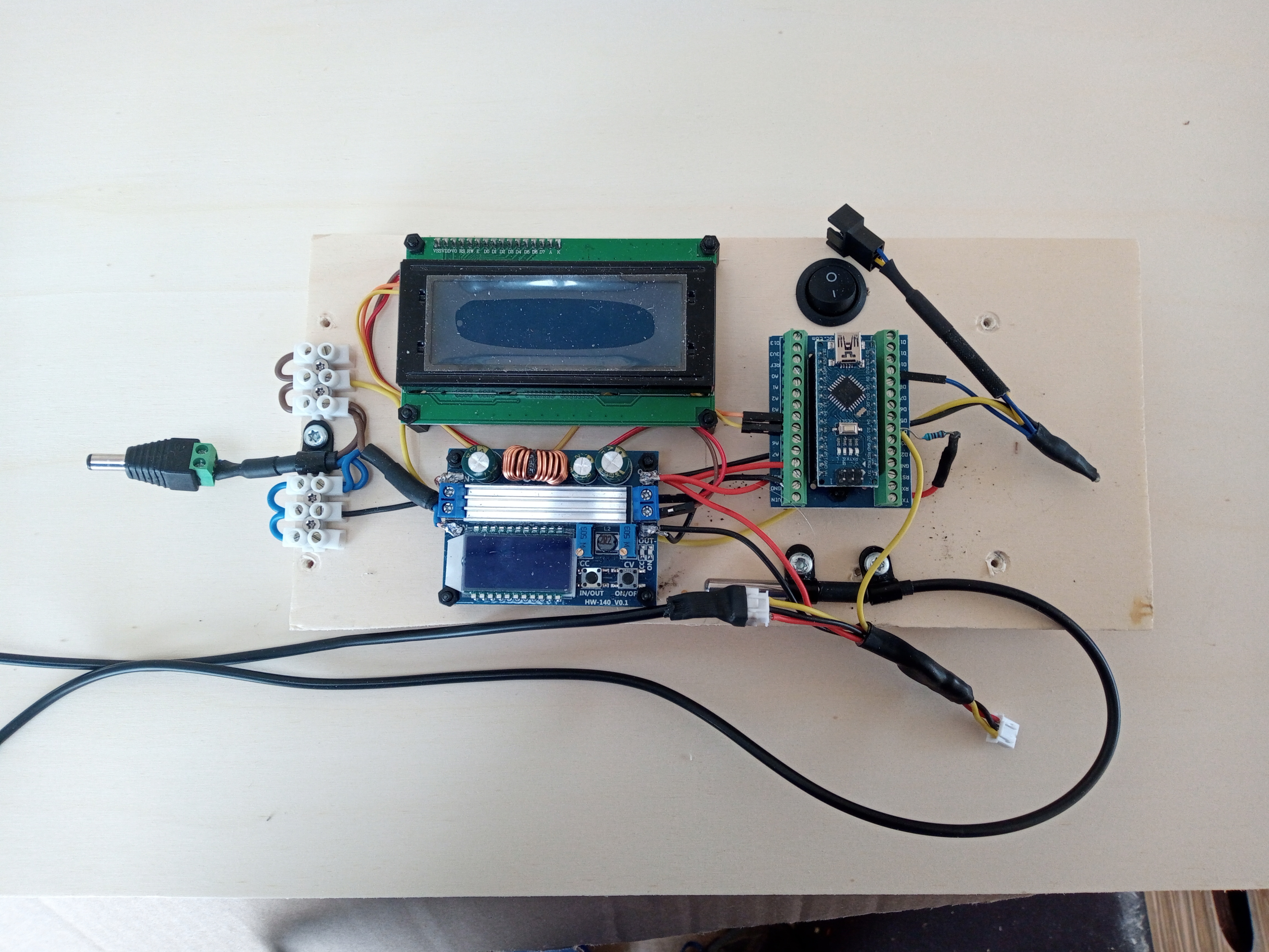
img-20210922-125615-789.jpg

On off switch is for the LCD backlight

0 Likes 0 ·
kevgermany avatar image kevgermany ♦♦ commented ·

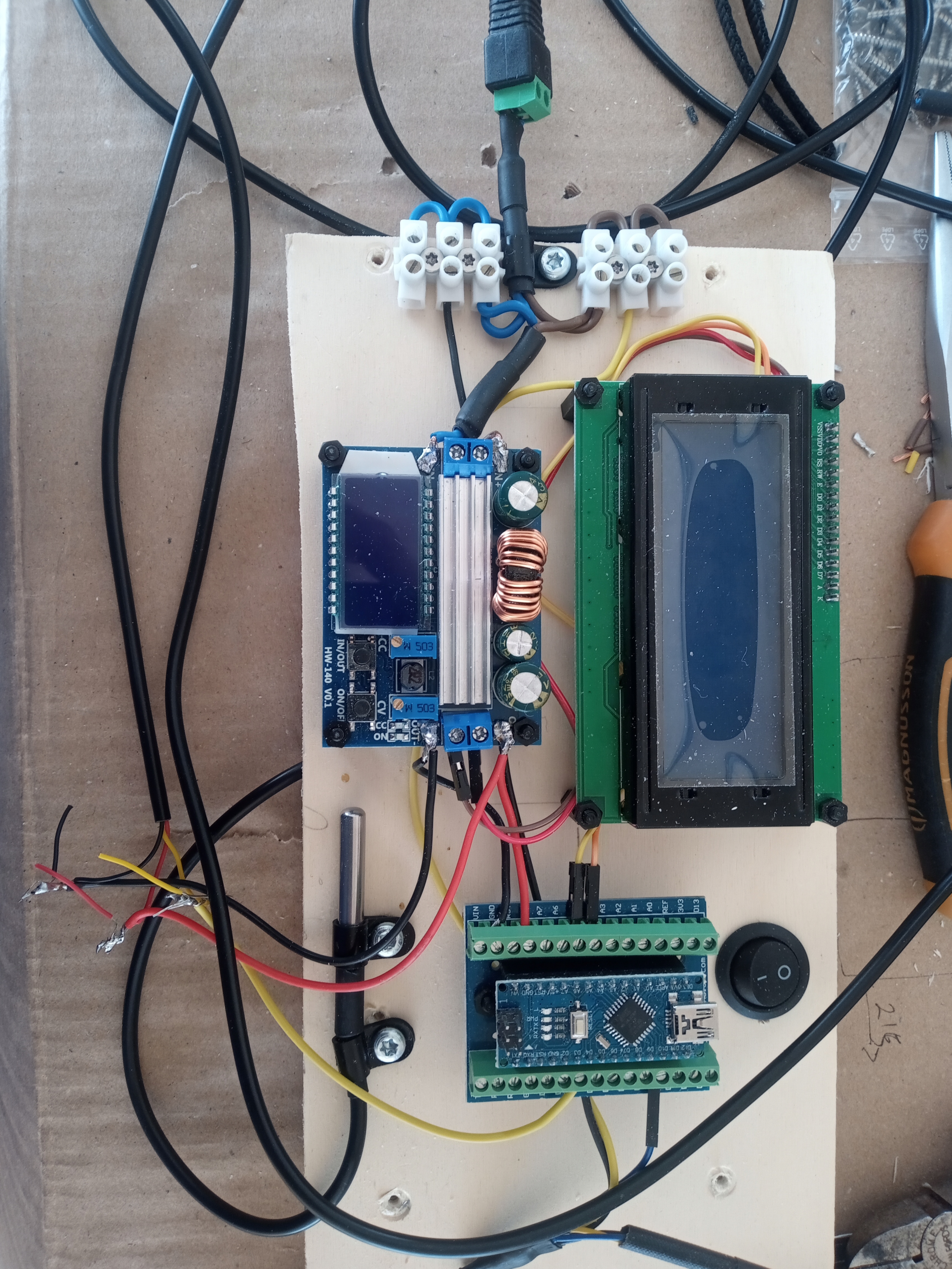
Fully assembled, obviously the wiring was tidied up afterwards

img-20210921-135308-531.jpg

0 Likes 0 ·
kevgermany avatar image
kevgermany answered ·

Output side of the Orions will be permanently connected to your leisure batteries, input side to starter battery, so switching automatically isn't an option.

PC fans require 12V input, should tolerate charging voltages.

Ideally get an integrated thermostatic pwm fan control.

I couldn't find one, so built my own, using a microprocessor, temperature sensors, cheap dc:dc voltage controller (just in case) and lcd display. If you want to try that, I'd be happy to share details, code etc.

2 comments
2 |3000

Up to 8 attachments (including images) can be used with a maximum of 190.8 MiB each and 286.6 MiB total.

t3z-gb avatar image t3z-gb commented ·
Hi @kevgermany

Thank you for your reply, yes please can you share your solution. Would be very helpful.


Regards.

0 Likes 0 ·
kevgermany avatar image kevgermany ♦♦ t3z-gb commented ·
Give me a little time to document, all in my head and camper at the moment. I'll move this to the modifications space.
0 Likes 0 ·
t3z-gb avatar image
t3z-gb answered ·

Hi @kevgermany this might be a stupid question but will the fan melt or explode connecting it directly to the battery ?

2 |3000

Up to 8 attachments (including images) can be used with a maximum of 190.8 MiB each and 286.6 MiB total.

Related Resources