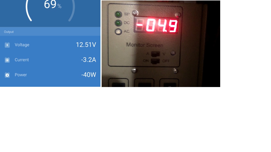
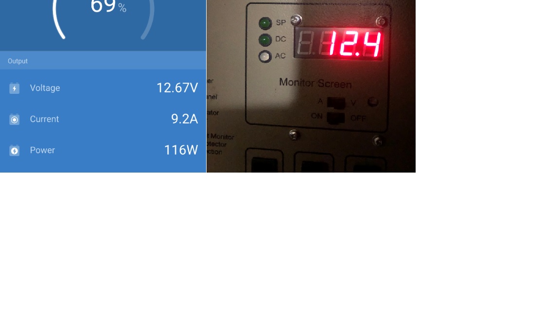
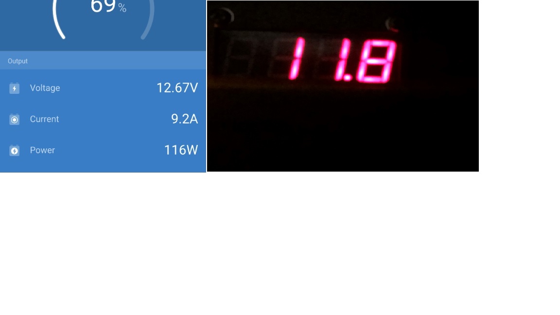
I have installed a new BMV-712 on my camper that has 2 x 12v 115AHr AGM's in parallel. I also have a separate Volt/Amp meter installed. The BMV reads current lower than what it actually is. 3-5 Amps on Charge and Discharge. 10mm cable used to connect the shunt?
I have no idea if the BMV is just not a very accurate device or how to investigate the problem
asked
BMV-712 Inaccurate Amp readings
The unit is definitely a lot more accurate than 3-5 amps, so something is wrong.
Please take some photos of your installation and post them, it might help to diagnose.
Also, how do you know it is the BMV that is giving the inaccurate reading, and not the other measurement device?
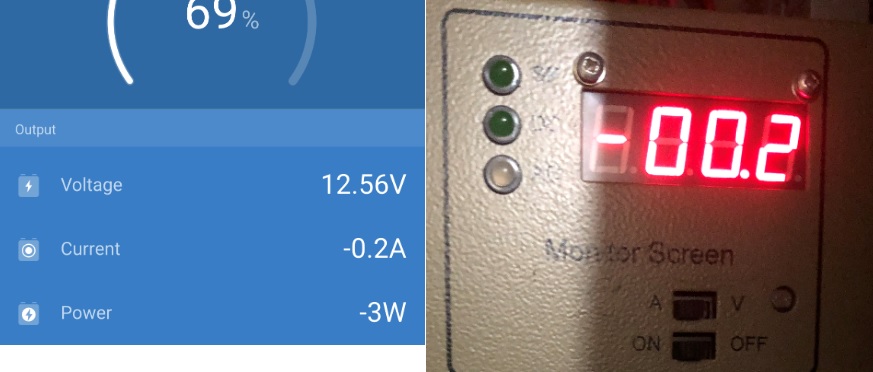
In addition to Guy's comments, did you perform a Zero current calibration when there is actually Zero current flowing?
This device should be very accurate. If it is not, then something is wrong.
@RynoRBO Please post photo's of the installation of the Shunt, this might help solve the issue.


The reason I am trusting the DB reading is because it has a 12Amp charger inside
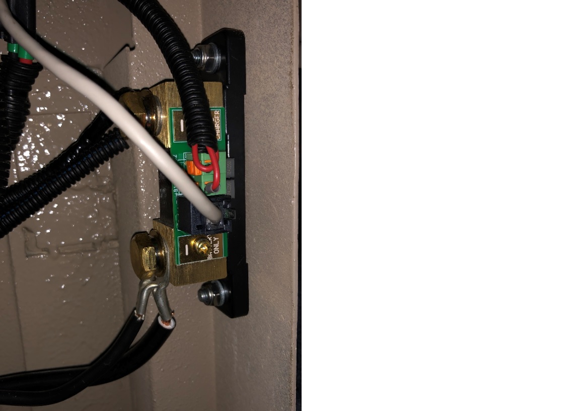
The picture and description with the shunt has me thinking.
I assume that the two wires between the battery and the shunt are just in parallel and go to the same battery terminal?
What does concern me is that after the shunt you say one wire goes to the DB and the other one goes to chassis. What this means to me is that there are now two different current paths for each shunt. The BMV shunt can have current from the DB and from chassis return to battery (current that will have bypassed the shunt tin the DB).
If you have two shunts then they need to be in series with one another with nothing branching off in between them otherwise they won't be measuring the same circuit.
The botom 2 wires comes directly from the -Neg of the 2 battery terminals
According to the Victron installation guide nothing other than the -Neg battery terminals must be connected there.
You make a good point on the chassis earth. I will have to investigate the potential of different paths
Your comment is quite a brain tease... What if I disconnect the chassis earth? Then the load cable goes directly to the -Neg of the DB board only.
That should eliminate multiple paths.. right? Even if just temporary to prove the point...
PS: The Camper was wired by the manufacturer. I just added the monitor
Some thoughts / recommendations;
1- Are BOTH current shunts positioned / wired directly to the battery terminals BEFORE ANY connections to loads or charge sources?
Or is the shunt related to the display that's reading higher current positioned / wired to / near the output of the charge source?
2- If both current shunts are positioned / wired on the negative side / cable, are they wired in SERIES?
3- Have you tried to PHISICALLY disconnect the wiring from all other loads & circuits (except the charger), then check the readings? (This test should prove/disprove a wiring issue with the 2x current shunts)
4- Do ALL devices / circuits in the system have a proper negative cable / wiring all the way back to the current shunts? (NOT just earthed to body / chassis & using that as the negative)
5- There have recently been a few BMV issues related to the UTP cable. You could try to slowly move the cable around near the connections on either end while watching the BMV display to see if anything changes.
6- Probably unrelated & I don't know what your max system current is, but 10mm2 wiring is very small for main battery cables. I would recommend at least 35mm2 as a minimum for most systems
7 - Lastly, if everything checks out OK, as already mentioned, there is a good chance that the BMV is the unit that reading correctly & not your other reference...
Good luck, Mark
1 - Yes the 2 Battery terminals are connected to the Battery screw on the shunt, other side is the Negative Ground and going to the DB Board
2 - I have only one shunt
3 - Low readings are in sync the higher it goes the bigger the difference
4 - Hmm I want to say yes
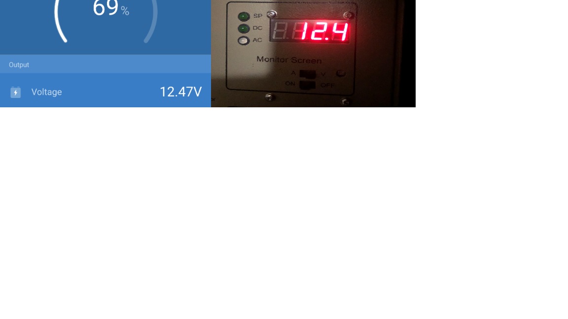
5 - The volts are completely in Sync, its just the Amps
6 - Wow 35mm , okay I suppose it can be the thickness, but would I not also see a voltage drop as an indicator. also note the cable is only 100mm long
7 - Good point - I would have to get a multi-meter and do another comparison
1 to 4- In order to measure current, your 2nd monitor must still have a current shunt/big resistor inside (wired in series) or alternatively it may have an inductive pickup that one of the wires run through.
Using an inductive pickup will provide a less accurate reading in comparison to a calibrated current shunt.
Grounding of battery negative should also normally be done directly at the battery terminals, rather than after the shunt. But you MUST be sure that no components in the system use earth as the negative conductor or there will be a direct path back to the battery that bypasses the shunt.

Now for your 2nd monitor to read the same as the BMV (due to the way you have it wired to the shunt) ALL loads & charge sources MUST be wired to the load / charger side of your 2nd monitor. Is this the case currently?
5 - The UTP cable issue can also effect the BMV current readings, but as things match under no load it's probably not that.
6 - There is no single correct cable size, it all depends on the max current (discharge or charge), the TOTAL cable length (in 2 directions - pos & neg), the max cable operating temperature & if the cable is run as a bundle or individually. If you are running a decent size inverter on 12v for example, yes 35mm2 or even much larger may be required.
7- If you can get hold of a high quality fluke multimeter (or similar) then you could use that to run some current verification tests, by breaking the circuit temporarily (at a few locations) and wiring it in series. You just have to be careful to ensure that the current is kept under the 10A multimeter limit during the tests.