question

James B avatar image
James B asked

MultiPlus 2 bespoke meter input

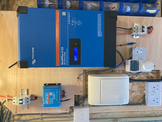
I would like to set up a MultiPlus 2 GX device as an ESS at home to optimise self-consumption. This will require a meter at my grid input.

I want to re-use my existing Aeotec ZWave meter that is input into Home Assistant so that I don't require any additional hardware at my already-cramped meter/consumer unit. However I see from the MultiPlus manual that currently only the ET series of meters are supported. This will also add ~£400 to my cost so I want to avoid that.

Reading through the mode-2 and mode-3 info here: ESS mode 2 and 3 , I can see there is a lot of scope for customers implementing their own control loops. I'd just have to continually update the 'Grid Power Setpoint' parameter via Modbus-TCP or MQTT, using either Home Assistant or some other adapter.

However, I'd like to let the MultiPlus perform the control loop itself via Mode 1 or 2, but input the meter data myself, ideally via TCP.

Does anyone know of a way to do this?

Ideally I could just publish the current grid import/export power in Watts via MQTT, DBus, or Modbus-TCP. Either to the GX device or directly to the MutiPlus device.

But if that isn't going to be possible, I'm thinking something like simulating an ET-112 meter by adapting my existing meter data into the correct Modbus format, and sending that in via TCP. If that's not possible I will adapt it into RS485, then the MultiPlus wouldn't be able to tell the difference between my adapter and the 'real' ET-112 connected via RS485.

The ET-100 series meters Modbus formats are described in detail here: ET100 Series Communication Protocol

One problem with this approach is I don't know precisely which values are queried by the MultiPlus, and at what sample rates. I don't want to purchase the ET-112 to reverse engineer the exact exchanges between it and my MultiPlus.


Anyone done anything like this? Does my approach sound ok, or is there a better one?

Thanks

Multiplus-IIESSEnergy MeterModbus TCPMQTT
2 |3000

Up to 8 attachments (including images) can be used with a maximum of 190.8 MiB each and 286.6 MiB total.

3 Answers
James B avatar image
James B answered ·

For future reference, here's a related (but fundamentally different) question: Grid meter over TCP/IP

This seems to indicate it is possible to bridge the Carlo Gavazzi sensors over ModbusTCP, so my "faking it" approach should theoretically work...but might be a pain to implement all the message exchanges/registers that the GX device makes use of.

A nicer solution would be to write in the grid meter data in a meter-agnostic format (i.e. so the MultiPlus/GX thinks its talking to a generic meter rather than a specific EM/ET-series one)

1 comment
2 |3000

Up to 8 attachments (including images) can be used with a maximum of 190.8 MiB each and 286.6 MiB total.

James B avatar image James B commented ·

Another relevant link to anyone trying to solve this problem - some good example code for integrating with Modbus TCP

My attempt at playing with Python Modbus & MQTT

0 Likes 0 ·
lifeingalicia avatar image
lifeingalicia answered ·

same reason no more space I use the current sensor and have it extended by 3 meter high quality earphone cable extension. If you use it dont forget to tick external sensor in ve config. I use Openhab and modbus but do grid set manually on the fly but this can easily be automated by complex rules etc..

1652703317331.png

hope it helps

I also use Iammeter as digital meter @ 150€ but it only updates every 30 seconds but the supporting cloud produces nice graphs....


1652703317331.png (11.5 KiB)
2 comments
2 |3000

Up to 8 attachments (including images) can be used with a maximum of 190.8 MiB each and 286.6 MiB total.

James B avatar image James B commented ·

Thanks, although that would be nice and simple + cheap, I don't think that will suit me either though (unless I absolutely have to)...

It's physical, aesthetic, and financial constraints driving this really.

The MultiPlus will be located in a shed 15 metres away, but with no good cable runs to get out to the shed - the CU is in the middle of my house, can't run any new cables under tiled floor to outside - would have to go up and across, which is a big pain. I don't want to risk doing all that then finding that the CT clamp signal is too degraded to use.

To expand further why I don't want an ET-112 or similar DIN-mounted meter...

The cupboard I have my Consumer Unit etc inside has almost no free space. There are no DIN slots left in my 16-module consumer unit for the ET-112, and a larger one would need me to build a whole new wider cupboard for it to go in. Also, my wife doesn't like that idea as it would chop off her shoe storage! That would lose me a lot of credit for messing around with solar stuff :)


Then I'd have to consider the price of the ET-112 (£80), two RS485 to Zigbee converters (£100 each = £200), a new Consumer Unit (£85) and somebody to fit it for me because I can't isolate the meter tails to fit the new CU myself.

So the wireless CT clamp I already own is perfect for my situation - if Victron offered one of these (at reasonable price) I'd almost definitely go for it. I just have to figure out how to adapt it...

0 Likes 0 ·
pau1phi11ips avatar image pau1phi11ips James B commented ·

You can get the ZigBee to RS485 converters for about £30 each from China if you ever did go that route btw. Looks like you're making good headway though.

0 Likes 0 ·
James B avatar image
James B answered ·

Just a quick update on my project...


My MultiPlus arrived in the post yesterday and I hurriedly installed it. After the physical installation was done I began work on setting up the control loop part of the ESS.

I ultimately decided not to go the route I suggested in my earlier post (Mode 1+ custom meter input), after discovery how easy Mode 3 was.


I now have Home Assistant running my control loop with a small set of Automations, the most complicated of which is basically a 5-line 'if' statement with some exponential moving average filtering (aka low pass).

I've made it so I can move a slider in HomeAssistant for "maximum watts to take from the battey" (aka AC Setpoint), and an overall binary toggle switch to enable/disable battery discharge at all. In future I will schedule this appropriately.

Anyone implementing Mode 3 needs to be aware of two important discoveries I've made (please correct me if I'm wrong here):

  1. You need to keep writing into the AC Setpoint register (slave 228/addr 37) periodically, or the MultiPlus will time out and disable all charge/discharge, falling back into ESS Passthru mode. This is a *brilliant* feature by Victron, because I was worried if my control loop crashed/rebooted/etc that the MultiPlus would be 'stuck' on whatever the last command I sent was, and this is dangerous. So Victron have put a timer on it (about a minute) so that stale data can't destroy your equipment. If Victron hadn't have done this, I was thinking I'd have to implement a watchdog script on the GX device itself, which I wasn't looking forward to, so thanks Victron :)
  2. This AC Setpoint watchdog timer requires different values to be written! So you can't just keep refresh/writing the same exact value in Watts. To resolve this, simply add a random number every time you write the register - I use [-1, 0, +1]. Another awesome feature by Victron that detects when the control loop still publishes data but the logic gets 'frozen' somehow. So this feature in is great at detecting that the mode 3 control loop logic is really alive.
  3. All the register indices are out by 1 in qModMaster. So for the AC Setpoint register (37), you actually need to read/write 'starting address' of 38. This is annoying, and not really documented anywhere. Not Victron's fault, its just a mismatch of industry standards. I'd say qModMaster should have an option for this really.
  4. Mode 3 is a *lot* easier than I thought it would be. Seriously. I was a bit concerned it would be far too low level, and I'd somehow wreck my MultiPlus or burn something out with it. When you're developing things make sure to set really low limits for things like charge/discharge/AC Setpoint so you can't accidentally command it to draw a massive amount from your batteries that would blow the fuse.

Lots more to improve in my control loop in future, but what I have now is better than I thought I'd have after less than a day of work.

Some pics...

img-6077.jpg

image0.png

image1.png

Moveable 4x12v Battery tray:

img-6043.jpg

Forgot to order a VE Direct cable...so DIY'd one:

image3.jpegimage4.jpegimage5.jpeg


img-6077.jpg (86.3 KiB)
image0.png (164.1 KiB)
image1.png (151.4 KiB)
image3.jpeg (141.5 KiB)
image4.jpeg (133.7 KiB)
image5.jpeg (92.3 KiB)
img-6043.jpg (126.4 KiB)
1 comment
2 |3000

Up to 8 attachments (including images) can be used with a maximum of 190.8 MiB each and 286.6 MiB total.

James B avatar image James B commented ·

Extracts from my HASS config YAML files, for those who are interested

configuration_fragment.yaml.txt

automations_fragment.yaml.txt


Here's a quick paste of the main control loop YAML (included in the automations attachment):

(Triggered by meter update, conditional on boolean toggle switch)

service: input_number.set_value
data:
  entity_id: input_number.slider_multiplus_ac_setpoint
  value: >-
    {% if is_state('input_boolean.grid_neutral_toggle', 'on') %}
    {%  set grid = (states('sensor.home_energy_meter_gen5_electric_consumption_w')| float) %}
    {% set acsetpoint = (states('input_number.slider_multiplus_ac_setpoint')| float) %}
    {% set maxfeed = (states('input_number.slider_multiplus_max_feed')| float) %}
      {
                    { [0, ([maxfeed,
                 (0.15 * (grid+acsetpoint)) +
                 (0.85 * (acsetpoint| float))] |
            min)+ ([-1, 0, 1] | random)] | max | int}}
    {%- else -%}
    {[0, 1, 2] | random}}
    {% endif %}

That automation writes out to a slider. Another automation triggers off the change to the slider and writes via modbus:

service: modbus.write_register
data:
  address: 37
  slave: 228
  hub: victron
  value: >-
    {% set val = states('input_number.slider_multiplus_ac_setpoint') | int %}
    {% if val < 5 %}
      {
                    {0}}
    {% else %}
      {
                    {65536 - val | int}}
    {% endif %}

The forum's formatting corrupts the double-{ above, it adds a newline...you'll need to fix if you copy/paste.

This YAML isn't very "polished" yet, it is the product of a single late night coding, so probably not the best example to copy paste - use with caution ;-)

It doesn't even do export limitation yet - so I still allow excess PV to be exported to the grid. Easily avoidable by changing the range on the slider.

1 Like 1 ·