question

love2learn avatar image
love2learn asked

Solar Design- Inverter and MPPT on bus bar

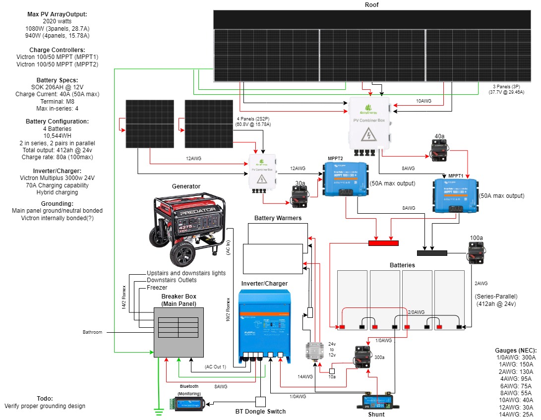
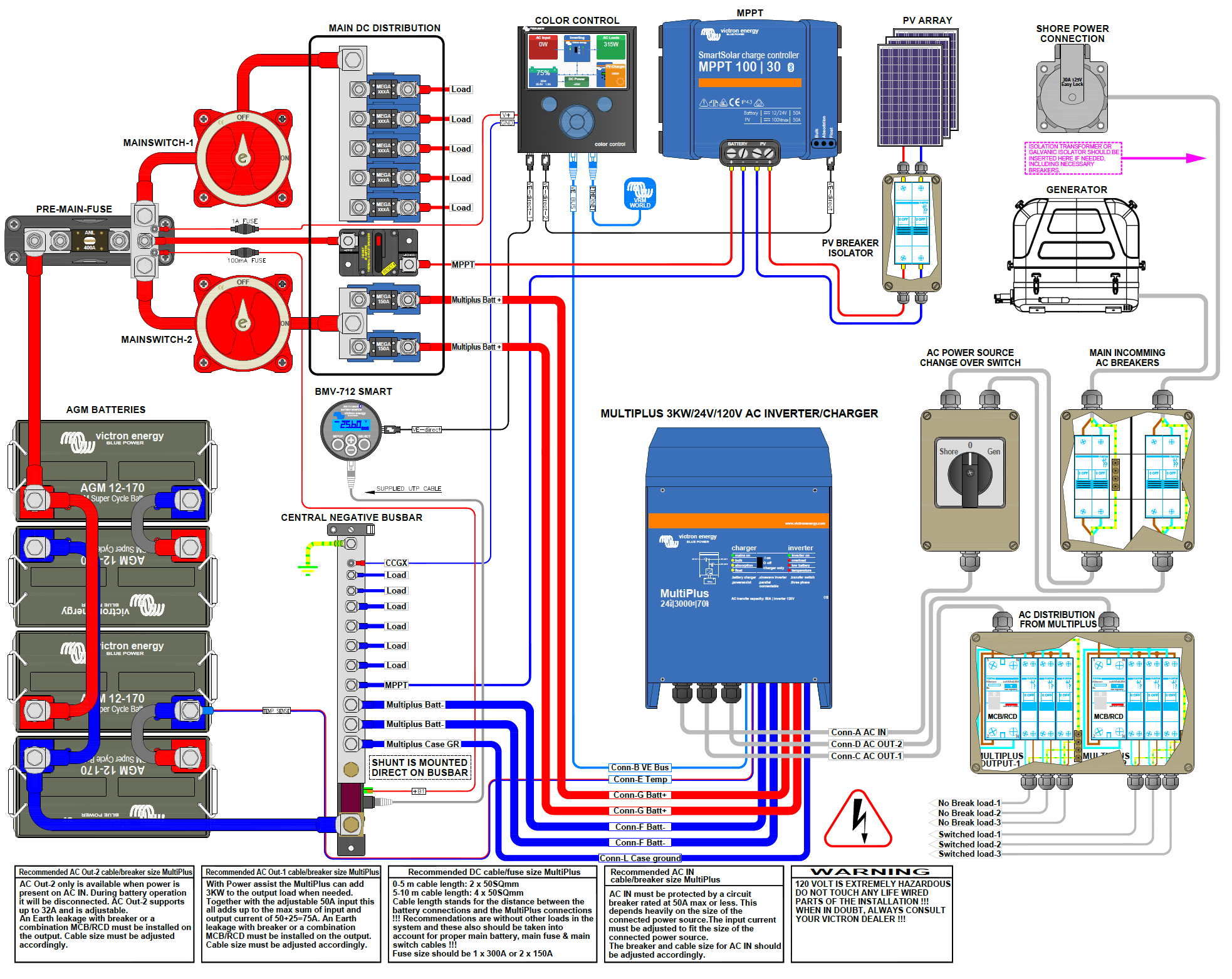
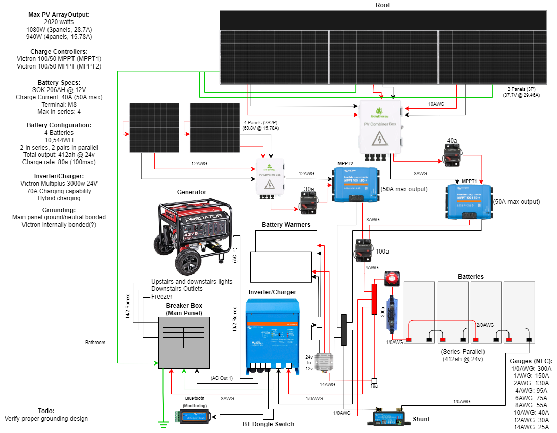
I was looking at the Victron Wiring Diagram.pngfor the 24v 3000w Multiplus and noticed that they have both the MPPT and inverter connected to ->busbar->battery bank. In my setup (Solar System Design (24v).jpg) I am using 4 batteries, 206ah @ 12v, 10.5kwh. The batteries are in 2S2P, so an effective 24v @ 416AH. I think this means I can discharge 200a? In my diagram you'll see that I have the 2 MPPTs on busbars, and those busbars are on the outer battery terminals. My inverter is connected to the inner terminals of the paralleled batteries. Which configuration is better and allows for more even charging and discharging?


(Note, the 300a fuse will actually be a 300a ANL fuse)

MPPT ControllersMultiPlus Quattro Inverter Chargerbattery chargingbattery
1 comment
2 |3000

Up to 8 attachments (including images) can be used with a maximum of 190.8 MiB each and 286.6 MiB total.

Alexandra avatar image Alexandra ♦ commented ·

@Love2Learn

How much amps you can discharge rather does depend on your battery bms.

0 Likes 0 ·
3 Answers
Sarah avatar image
Sarah answered ·

Because you are not monitoring both battery charging and discharging you will not get a state of charge (SOC). You will be forever guessing how charged your batteries are. Also given that you don’t have a significant DC system the inverter will give you a good indication of the actual load. If you want an accurate load measurement you can install a second smart shunt and configure it as a DC meter. Have a play with the smart shunt in Victron connect (demo Library) and you will see the differences. Finances permitting an install of this size would benefit from a Cerbo GX which will give you everything on one screen. As for maximum DC discharge current this will depend on the type of batteries - have a look at the spec sheet. Given your config the total discharge current (@24v) would effectively be twice the Individual discharge (@12v).

4 comments
2 |3000

Up to 8 attachments (including images) can be used with a maximum of 190.8 MiB each and 286.6 MiB total.

love2learn avatar image love2learn commented ·

You're right. My usage is all 120VAC loads, with the exception being the battery warmers in winter which are DC. I have a 24v to 12v converter post-shunt which should mean all loads are accounted for in the shunt right?


I updated my diagram to be more like the Victron reference. It sounds like this should give me accurate SOC readings now?Solar System Design 24v (busbars).png

0 Likes 0 ·
klim8skeptic avatar image klim8skeptic ♦ love2learn commented ·
I think you could wire the 2 warmers in series and do away with the 24>12 converter.

Worth asking the supplier?

0 Likes 0 ·
love2learn avatar image love2learn klim8skeptic ♦ commented ·
I'll give that a shot. Thanks!
0 Likes 0 ·
Sarah avatar image Sarah love2learn commented ·

The revised design has the correct location for the smart shunt.

0 Likes 0 ·
klim8skeptic avatar image
klim8skeptic answered ·

The smartshunt wont measure solar generation with your wiring proposal.

2 comments
2 |3000

Up to 8 attachments (including images) can be used with a maximum of 190.8 MiB each and 286.6 MiB total.

love2learn avatar image love2learn commented ·

I thought the shunt only measured egress, and that the MPPTs measure the ingress? So then in my setup, if I were charging at 50 amps, and consuming 20 amps, logging into the shunt would show "-20A" instead of the "30a" if it were wired like Victron's diagram?

0 Likes 0 ·
shaneyake avatar image shaneyake love2learn commented ·
No. The only negative connection to the battery should be the shunt and everything gets connected to the shunt. Load or Charger.
0 Likes 0 ·
wazycolen avatar image
wazycolen answered ·

Where did you get this information from?

2 comments
2 |3000

Up to 8 attachments (including images) can be used with a maximum of 190.8 MiB each and 286.6 MiB total.

southsideph avatar image southsideph commented ·
Which information are you looking for as I'm in the process of designing similar, Question has been answered but I may be able to point you in the right direction for some information


Rgds

0 Likes 0 ·
love2learn avatar image love2learn commented ·

Im not sure what you're asking. Where I got the battery discharge info from? Where I got my diagram from? Where I got the Victron diagram from?

0 Likes 0 ·