Hello Community. Two questions for you this morning.
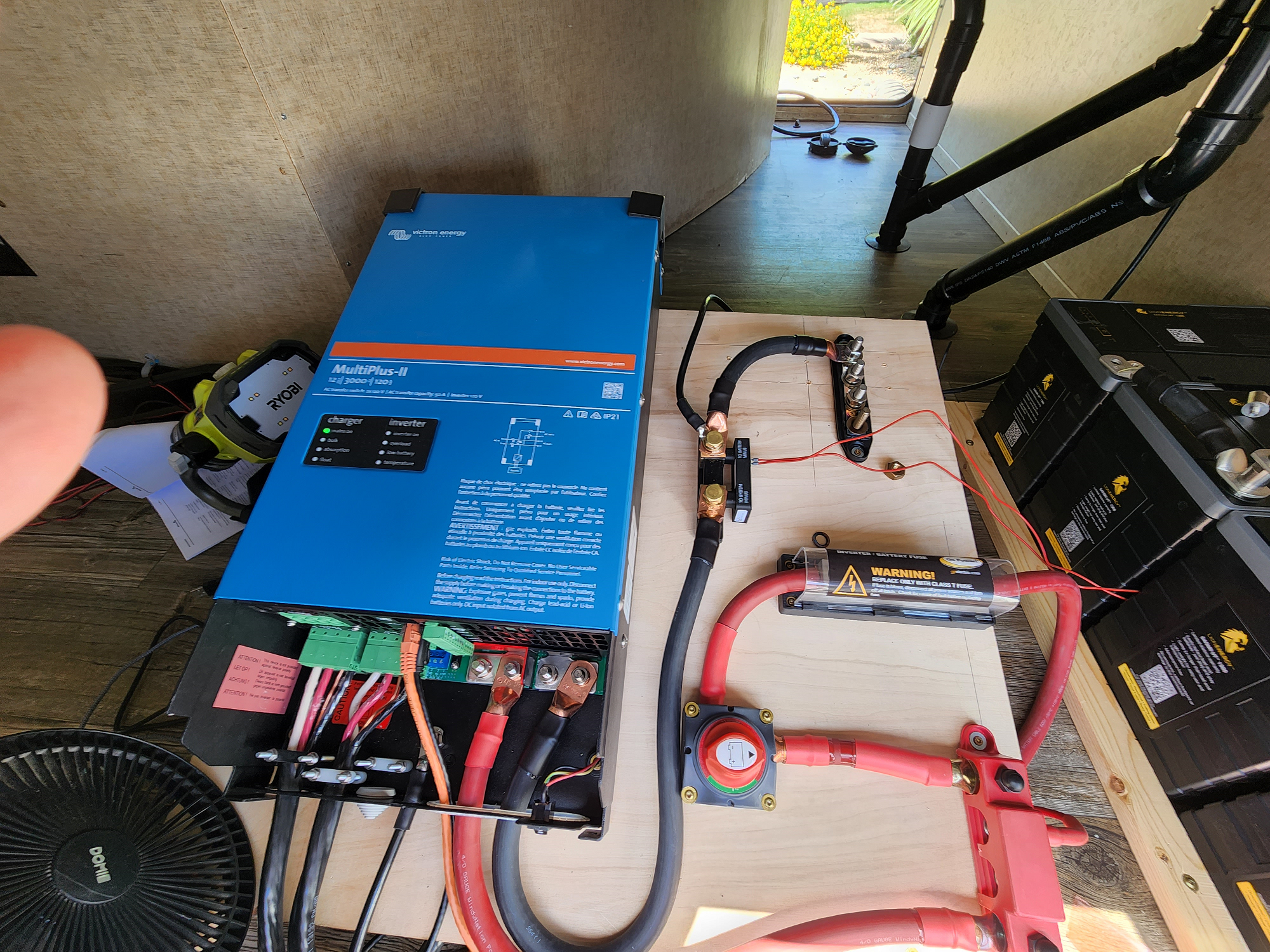
I just installed a MultiPlus-II 12V/24V 3kVA 2x120V in my 5th wheel. Power on is good and everything looks OK. Connected to 50a shore power. Both AC runs, everything seems to power OK - Victron is a little warm, but manageable. But when I connect the battery bank (4x 100Ah LiFePO4 connected in parallel), the battery cables get VERY hot - too hot to touch and the compartment is extremely warm to the point Victron will eventually shut off. Specifically the negative side is very hot. Positive is warm, but not bad. What could cause that? The batteries were about 50% charged when I connected it. I enabled Lithium setting in the Victron Connect SW. I used 4/0 cables. Built cables myself.
Also, rookie mistake (HUGE oversight, I know that), I left the ACs on, then disconnected my shore power because Victron and batteries were running too warm last night. This morning when things warmed up, ACs came on and hammered my batteries, which made the negative cable smoke and completely melted the plastic on my bus bar. I consider myself very lucky I didn't burn down the place. Now, I'm worried if there is a power outage or bad connection, that I'd really cause an issue because I didn't know it switched to battery and AC still runs. Is there a way to have the battery power draw cut off at a certain level so I don't cause a fire is this happens?
Here is my setup.
asked
MultiPlus II & Batteries Very Hot
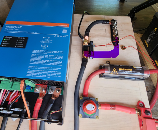
I think you should move the negative busbar to the other side of the shunt, and not run the multi through it.
@klim8skeptic Thank you. Do you mean take the bus bar out of the negative path from Victron to the neg battery post? I did intend to have a one or two connections there.
https://www.cerrowire.com/products/resources/tables-calculators/ampacity-charts/
According to this link, at the currents you will have, your cabling will run very hot...
Sounds like you have some serious (dangerous) voltage drop. How much current is flowing through the 4/0 cable when this occurs (or under max load)? Hopefully you have a DC clamp-on ammeter.
You said you used 4/0 cable. What is the total run length from the battery to the inverter on the pos & neg sides? How did you crimp the terminals?
While under max load, measure the voltage at the battery terminals. Measure the voltage at the inverter input. Ideally you'll have 2% or less voltage drop while under max load.
If you're reading significantly higher than 2%, you'll need to measure the voltage drop at each subsequent terminal crimp and connection to find the exact source of the voltage drop while under max load. Keep one test lead on the pos battery terminal, then work incrementally towards the inverter pos input with the other test lead. Do the same on the neg side.
Good luck!
@ks_vic My total run thru fuse, switch, and bus bar is about 40" for positive and about 36" for negative.
Thank you for the instructions on testing voltage drop. I crimped the cables myself using a hammer lug crimper and my table vice. Is there a better way? I do have a DC clamp-on ammeter. I will test based on your instructions.
4/0 cable is rated for 200amp
200a X 12V = 2400W
there it is your problem, yo are at limit with that unit on wire size, use a second 4/0 cable and you should be fine.
And also check you connections and read the amps flowing with an Amp Clamp meter.
@SebastianLehmann I agree. My primary mistake was leaving the AC on. Do you think it's worth putting a 200a breaker on both the neg and positive side to cut off power if the ACs were left on again?
Thank you all for looking at this. After looking at this more, I think I've made some other critical errors outside the previously stated.
- Leaving the ACs on was my biggest mistake. I didn't/don't plan to run either unit off battery, I'd always be plugged into generator or shore power for AC. Having both running easily pulled close to 3000w, which was not intended.
- The two bus bars are only rated at 250a. Most of the hot areas where at those junction points. I'll upgrade.
- I don't think the wire from neg battery to buss bar was tightened properly.
- The fuse I have on the positive side is 500a, which makes no sense to me. I'll admit, I'm a rookie. Why would I need 500a if I need it to trip much lower to protect the battery? That's me following a guide blindly and not thinking it thru. Replacement on the way.
- If I factor in the bus bar, fuse, switch, the total length from pos terminal to Victron is about 40" - negative is about 36". Is that too long?
Fuses protect (or should protect) the wires. Not the equipment.
The fuse should blow well before the current gets close to dangerous levels for that wire.
you can program you multiplus to Only have AC out 2 powered when AC In is available. so Connect your ACs units on that one and this would never happend even if you miss it.
I didn't know this was possible. Thank you. That would be a very easy solution and peace of mind.
If I remember right that AC2 out is only 35A, but even running two Air conditionings at ~12-14a each, I think it could handle it. I guess I'd pull the hot wires on both ACs from the existing breaker panel, put on an inline breaker, and tie the ACs to that. Probably adding a soft start to at least one AC unit would be good too.
Look on it this way. You've had a relatively cheap melt down which could have been much worse.
All parts of the system should be able to handle the full rated power through them, in this case the battery connections/DC side. This must handle full power continuously. The suggestion above about doubling the 4/0 cables may not be enough if you have 2 A/C units that can draw the full inverter output. So must the batteries. AC out 2 limit is effectively the full inverter capacity... And with both A/C units running off them, you're discharging at about 1C. Probably twice the permissible max.
Fuses are for errors/faults. You should design so they don't blow. Otherwise the system will be unreliable