question

skaada-xx avatar image
skaada-xx asked

Probleme Controlling victron with a plc

Hello,

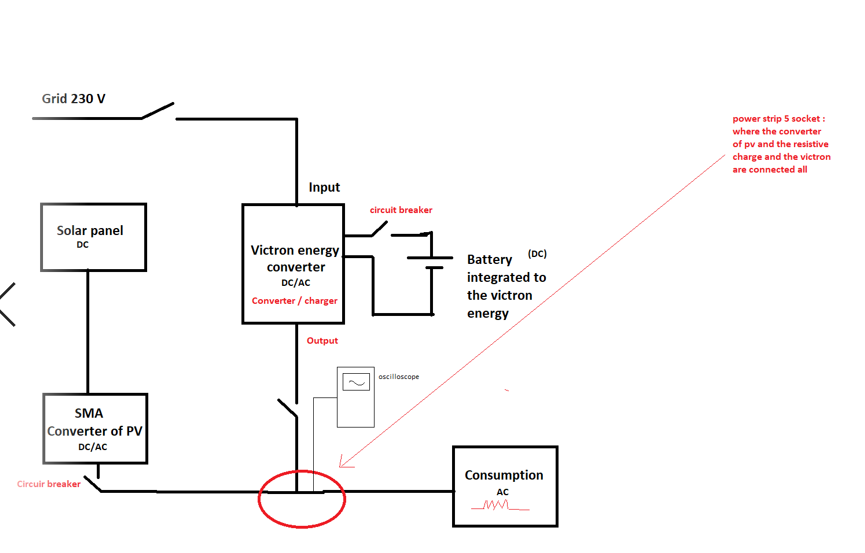
i'm working on a victron system connected too 2 sources of energy (Grid and PV, NOTE : the 2 inverter are not interfaced together, they are independant ) so i have a :

- Battery lithium-ion 2kWh

- MultiPlus-II 48/3000/35-32 (victron)

- Venus controller

- an SMA inverter 2000 W

- 6 Solar panel ( 365 Wc)

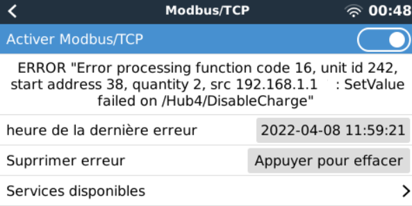
- the communaction with the victron and plc is via modbus TCP/ip

- plc (modicon m340)

what i have to do is to create a code in a plc (modicon m340) where i can control the system and maximise a self consumption, the priority is to take from the PV, and not from the grid, send the surplus to the battery if its SOC is low, not feeding into grid unless if we have critical cases (like when the battery is full, and no loads are applied, in this case we can feed in the production of the pv into grid),


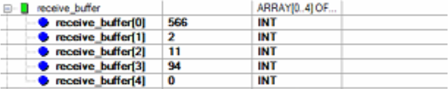
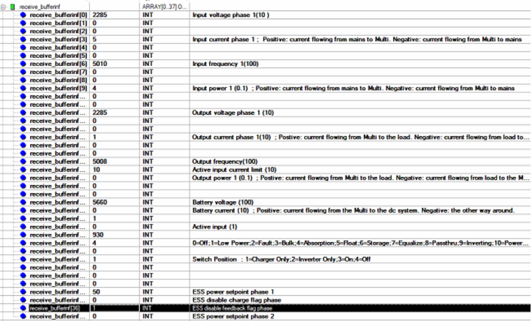
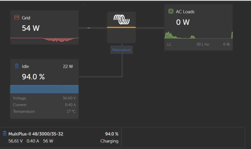
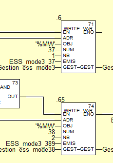
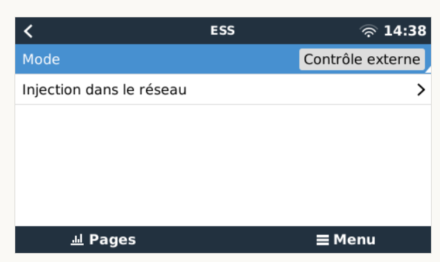
so for now i have did a program where i use ESS mode 3 ( using register 37,38,39), but my problem is when i run the code, and verify the vrm portal, it doesnt do what i tell him, the grid set point is never taken by consideration ( that's a first probleme), its continu feeding into grid even if i disable this, the power taken to charge the battery is always low ( 14W) even if the pv are producing 1600W, if i set the gridset point on 0W (it means not giving power from grid) but it continu sending power to the multi, is it possible to controle the power sent to charge the battery ?

how can we calculate the value of the grid setpoint ( it said its from -32668 to 32668 but when i choose for example to take 0W, it doenst work, take 500W it doesnt also workk, no value is working),


i've read the manual of ESS mode 3 and 2, and implement even the examples writen in it, (how to charge, discharge, ..... but none of these example worked )

if i set 37:0W & 38:0 & 39:1 ==> it has to charge the battery without feednig back into grid but no it continu feeding into grid, and the power taken to charge the battery is very low (over 22W) ,


Please if someone already faced these problems can he respond me with a correct answers, what i have to do, what i'm doing wrong, what should not do ? plsss plsss


Thank you for help,

and plss if someone sees my question and know how to help me, it will be very helpful pls

Multiplus-IIModbus TCPSolar Panelvictron productsvictron community
2 comments
2 |3000

Up to 8 attachments (including images) can be used with a maximum of 190.8 MiB each and 286.6 MiB total.

Best to first use mode2, and if that works well, go to mode3 if you need that.
0 Likes 0 ·
shaneyake avatar image shaneyake Daniël Boekel (Victron Energy Staff) ♦♦ commented ·
It turns out, it is a battery problem. Battery is currently commanding CCL 0A and DCL 0A. Cell imbalance it looks like, so inverter won't respond to commands which is expected is this condition.
0 Likes 0 ·
2 Answers
tnt369 avatar image
tnt369 answered ·

It is necessary to write the registers (37-39) every minute or more often. Otherwise they will be ignored.

Have you tried to write the Grid-Setpoint to the System-Unit (100) in Register 2700? This is how my system works. I don´t use the registers 37-39.

7 comments
2 |3000

Up to 8 attachments (including images) can be used with a maximum of 190.8 MiB each and 286.6 MiB total.

skaada-xx avatar image skaada-xx commented ·

thank you for you response i areally appreciate that,

yes i already did that, i write every 30 s in the register 37,

when you said (37,39) you meant both or all of them (37,38,39) ?


you use 2700 so its the ESS mode 2 ( in the vrm i have to set optimised not external control ?) , i've tried it also but it didn't work also, can you share with me more details pls if it not confidential plss

thank you so much


0 Likes 0 ·
tnt369 avatar image tnt369 skaada-xx commented ·
okay, step by step:

Are you able to see values by reading via modbus? For example DC-Voltage, State-of-Charge ...?

Is the bms of the battery connected to the venus controller?

And show me a drawing of your wiring, so i want to understand how your system ist build.

0 Likes 0 ·
skaada-xx avatar image skaada-xx tnt369 commented ·

heello, sorry for my late response,

yes i'm able to read the different information of the battery , for example in the image below i read the values of the registers 840 to 8441649530179341.png

and in this photo there is the values that i read from register 3 to 39,

1649530229286.png

a simple wiring of the system that i've drawed my self is like that :


1649529916247.png

i forgot to mention before that we are using a charge resistive like a consommation

1649530001476.png

and this is a photo of the vrm

1649530116541.png

0 Likes 0 ·
shaneyake avatar image shaneyake skaada-xx commented ·
I can't see the images you posted.
0 Likes 0 ·
skaada-xx avatar image skaada-xx shaneyake commented ·

i'm going to repost my comment so that you can see the images :

heello, sorry for my late response,

yes i'm able to read the different information of the battery , for example in the image below i read the values of the registers 840 to 844

1649540688466.png

and in this photo there is the values that i read from register 3 to 39,

1649540733159.png

a drawing that represent the wiring of the system that i've drawed my self is like that :

1649540820758.png

i forgot to mention before that we are using a charge resistive like a consommation

1649540852915.png

and this is a photo of the vrm :

1649540881699.png


0 Likes 0 ·
1649540688466.png (90.3 KiB)
1649540733159.png (408.4 KiB)
1649540820758.png (57.2 KiB)
1649540852915.png (269.2 KiB)
1649540881699.png (57.6 KiB)
kevgermany avatar image kevgermany ♦♦ skaada-xx commented ·
@tnt369

@skaada xx

Moved to modifications community. Better there.

0 Likes 0 ·
skaada-xx avatar image skaada-xx kevgermany ♦♦ commented ·
sorry i didn't understand ?


0 Likes 0 ·
shaneyake avatar image
shaneyake answered ·

Okay, just to get some details correct.

This is a single phase system.
You have set ESS to mode 3.
You are sending valve: -100, register: 37, Slave ID: 227, Function code: 6
Does it export 100W?
On the GX - > Settings -> Services -> Modbus TCP ->
Do you see any errors?

5 comments
2 |3000

Up to 8 attachments (including images) can be used with a maximum of 190.8 MiB each and 286.6 MiB total.

skaada-xx avatar image skaada-xx commented ·

hello, yes this is a single phase system, i'm using ESS mode 3, i tried sending many value to the register 37, unit id 242, it does show me in the table of animation that any value i've sent is taken as shown is the images below, but the victron does not take by consideration any of these values when i check in the vrm, i don't know why !

(the function code that you sais what does it mean ?)

normally the register 37 is from -32668 to 32668 ( how do you calculate the exacte value that you want to send, for example if i want to take 100W i just have to write 100 or there is a methode, formul, that i have to use?) bc i heared that there are some values that the victron does not know them,

i'm actuaally trying to use 0W (to not feed back and to not take from the grid when i 'm charging the battery from the surplus of the pvs, but eveen 0W does not function :/)


0 Likes 0 ·
skaada-xx avatar image skaada-xx commented ·

and for the error that you asked, this is my first time knowing this part of (( services --> modbus TCP )) , i checked it now and this is what it shows

1649631051617.png

0 Likes 0 ·
1649631051617.png (74.2 KiB)
shaneyake avatar image shaneyake skaada-xx commented ·

Function codes are part of modbus, it is like the type of request.

You can read here for all the options supported by Victron.
https://www.victronenergy.com/live/ccgx:modbustcp_faq

From the modbus spreadsheet, you will see a scale column for register 37 it is 1.
So writing 100 is 100W. Observably if you try set like 4000 and your inverter can only really do like 2500W, it will just max out at 2500W.

One thing to keep in mind is that modbus can be funny as some equipment counts 0 as the first register and others count 1 as the first register.
As you can see by the error it says you tried to write 38 and not 37. Just reduce the number on the PLC by 1. I would also try to a single write code 06 and once that is working switch to a multiple write 16, like the error said you tried.

Can you post a screenshot of your ESS menu?

0 Likes 0 ·
skaada-xx avatar image skaada-xx shaneyake commented ·

ok i will try to do that now and see what will happen, and tell you if it works

but even that its a little bit weird what i see it the error bc i'm already trying to write separatly in 37, and (38-39 together) look :

1649680658933.png

(by the way i'm using UNITY PRO as software to controle the victron by plc)

here is a screenshot of my ESS menu ; it is set to exetrnal control bc i'm using mode 3

1649680702940.png

0 Likes 0 ·
1649680658933.png (10.0 KiB)
1649680702940.png (26.3 KiB)
shaneyake avatar image shaneyake skaada-xx commented ·

Okay, Can you try to only write to 37 and see if you get an error on the GX?

0 Likes 0 ·

Related Resources