As someone trying to install one of these isolators I have searched high and low to try and answer my question. Jeff from Yacht systems has multiple YouTube videos but seems to gloss over most of the important details of the install. I find Victron installation instructions bland and lacking in explanation making the diagram irrelevant for most real world boat applications.
The Isolator Negative and energize connections are shown simply and without advice on purpose or placement. Also there are several posts that discuss back-feeding issues; blowing fuses and funneling power through what is supposed to be only a low amperage circuit. There is very little description of what this circuit is doing inside the Argofet or the Argo Diode systems.
I am hopeful people that understand these can try to compile answers here for others to understand more easily as well as help my own situation.
My application: 2001 Chaparral 240 Signature single engine Mercruiser 5.0 w/ 70 amp alt (3 wire), two AGM group 31 Batts, 4 position switch, currently a 20 year old Guest diode isolator, and wired in typical fashion with the alternator B+ output to the starter post then back to the isolator and then batteries.
Questions:
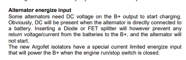
#1 On an application with a typical stock internally regulated mando, mercruiser, GM style alternator. How relevant are the energize inputs on these isolators in that setting? Victron manual states the Energize circuit is optional...
(seems it would be nice to keep it simple and avoid back-feeding issues by omitting the positive energize connection)
#2 If it is not used what will the unit not be able to accomplish? (will voltage drop be higher without?)
#3 Is anyone able to confirm that the energize circuit is truly only needed for older alternators that do not have a self excite, or an externally regulated alternator? (if truly optional who can omit?)
#4 If the Positive energize connection is needed... -
Diagrams show that it is spliced into the alternator Sense position. Will this not back-feed through the harness to other loads? I am assuming I can not simply wire this directly to my alternator and separate the sense (purple) from the rest of the harness. I would imagine that would disrupt an input to the PCM and confuse something important. It is hard to tell weather the isolator wants to output a voltage at the excite or input a voltage from the excite.
#5 Could someone clarify the purpose of separating the charge current path from the Isolators point of view. (remove daisy chain from alt to start, and wire direct to batt/isolator.)
I really hate the part in every video from Pacific yacht systems where the installer states "I am not going to go into details why".... but then elaborates on needless points the rest of the video, just adds to the mystery.
-Is this only to maximize the voltage and limit the drop through the multiple connections?
#6 Can the same answers be applied to the ArgoDiode series of isolators?
Thank you to anyone who is able to contribute.
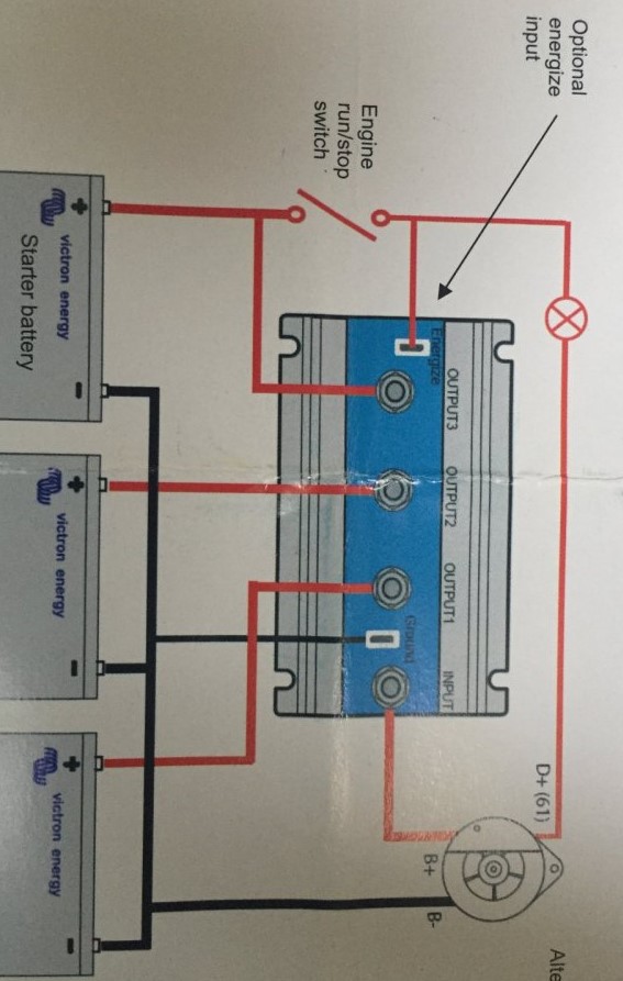
Photo shows Victron suggested install diagram. D+(61) = energize circuit