question

zulu-55 avatar image
zulu-55 asked

BMV712 Smart Battery Monitor question

Hello,

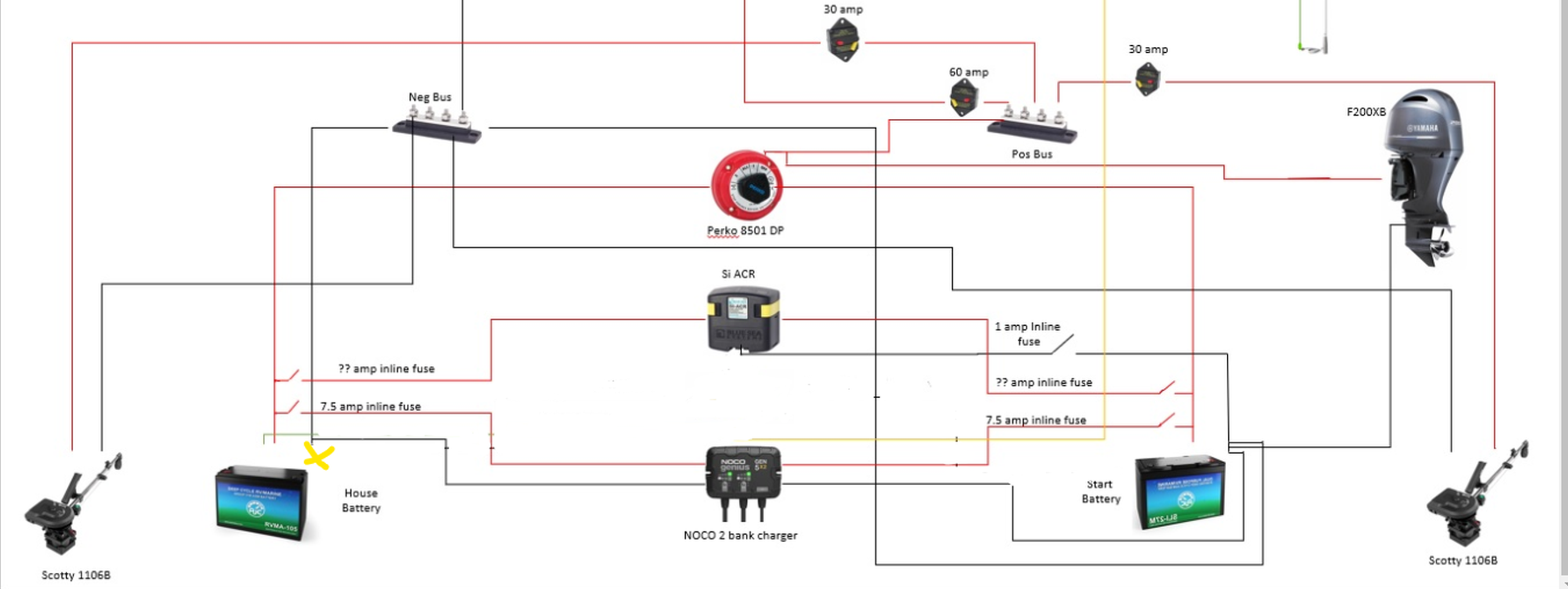
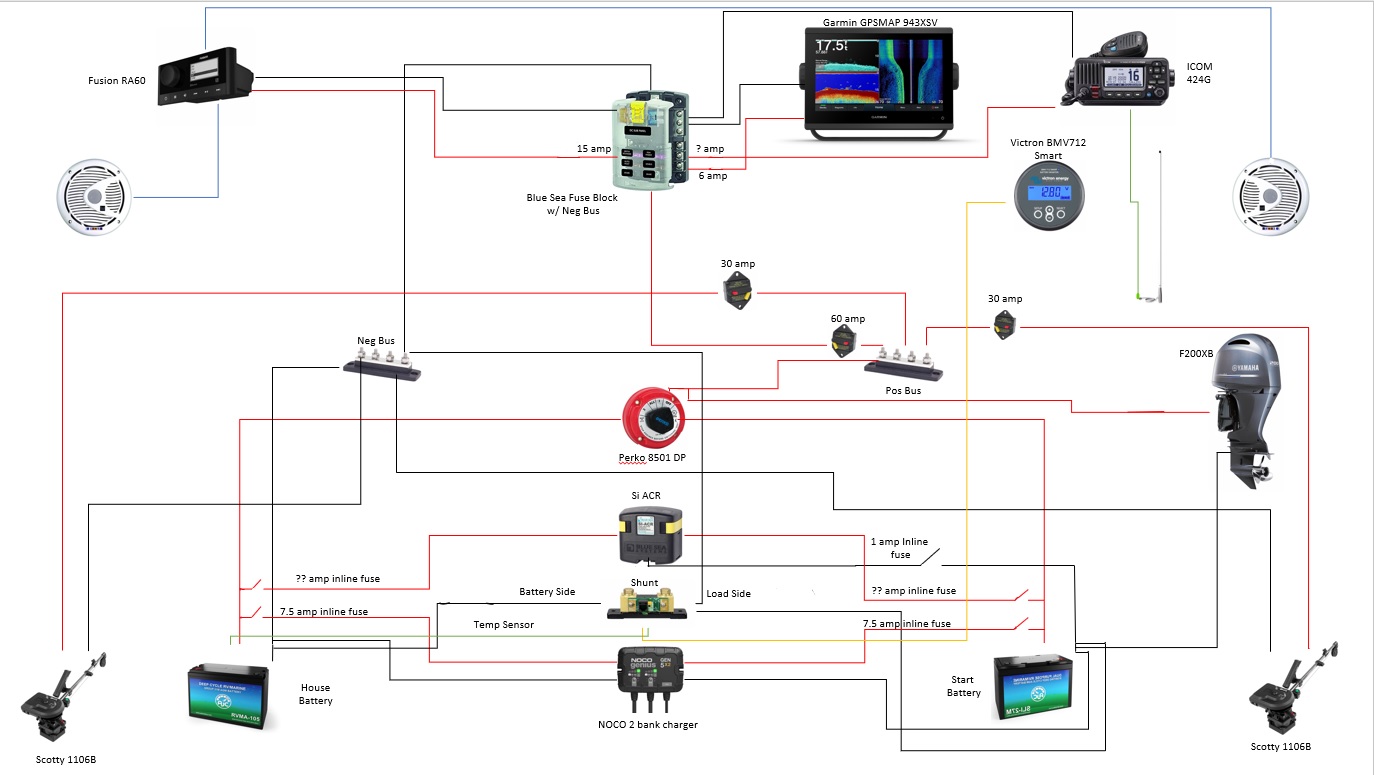
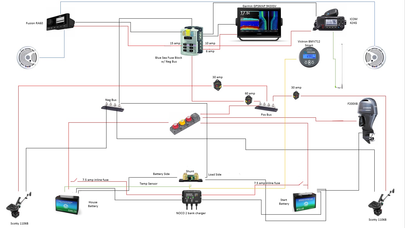
I have a BMV712 Smart battery monitor and I am trying to connect it to a dual battery setup on my boat. I have the temp sensor version. I am having difficulty interpreting where I should hook the sensor up. Should I have two because I have two batteries? Or prioritize a single battery (which one?) I've attached my schematic for your review. I appreciate any assistance you may be able to provide.wiring-schematic-final-version.jpg

BMV Battery MonitorTemperature Sensorschematics
1 comment
2 |3000

Up to 8 attachments (including images) can be used with a maximum of 190.8 MiB each and 286.6 MiB total.

Kevin Windrem avatar image Kevin Windrem commented ·

If you want to fully monitor both batteries, including state of charge then you will need 2 BMVs, one connected to each battery. You can not monitor both batteries with one BMV because it needs to measure current in and out of the battery (bank). Most people only monitor voltage on the starter/crank battery.

As mentioned previously, the shunt of the BMV needs to connect directly to the battery negative with NOTHING else connected to that side of the shunt. In fact, your diagram shows BOTH sides of the shunt connected to the house battery negative and the negative busbar.

Here's a diagram that might help:

https://www.victronenergy.com/upload/documents/DS-Lucians-Victron-Van-Automotive-Alternator.pdf

0 Likes 0 ·
4 Answers
kevgermany avatar image
kevgermany answered ·

As I understand it, your question is starter or house battery.

Most starter batteries get used for little except starting the engine, then the alternator takes over and handles the loads. Also they're charged direct from alternator which has no temperature compensation. So little need for it on the starter side.

The BMV is designed to monitor a single battery bank fully, and voltage only on a second battery.

Looking at your schematic, it looks as if you're not wiring the BMV properly.

It should be connected directly to the negative pole of the house battery. Nothing else should be connected there. All the negative connections, including battery grounding, should be to the load side of the shunt. No exceptions.

There must also be a good connection between the house and starter battery, looks like that's in. If they're separate systems, voltage on the starter will be wrong.

So temp sensor to house battery, look at shunt wiring.


5 comments
2 |3000

Up to 8 attachments (including images) can be used with a maximum of 190.8 MiB each and 286.6 MiB total.

zulu-55 avatar image zulu-55 commented ·

Ok, so if I understand you correctly:


The two batteries will be connected via negative terminals, then, 1 neg wire to the shunt. Then, 1 neg wire from load side of shunt to the neg bus. All other neg connections attached to the neg bus? I do believe I have it that way in the schematic. The only other wires going direct to one of the neg terminals is a small ACR wire (which I have been advised must be connected directly to the neg terminal of one battery, I had assumed crank battery so that it can ensure the crank battery is always good to go? But I now see my schematic has the ACR neg wire going to the house battery, I can change that so that it is connected to the crank battery) and my dual bank battery charger (which I was also advised must be connected to the neg and of course pos terminal on each battery). Looking at it closely though, I do also see the engine Neg wire is hooked direct to the neg terminals. Should I relocate that to the neg bus? Or is that a no-no? I figured it was best connected direct to the neg battery terminals.

With respect to the temp sensor wire, thank you so much. I will ensure it goes to the house battery :-)

0 Likes 0 ·
kevgermany avatar image kevgermany ♦♦ zulu-55 commented ·

Starter battery neg to load side of shunt/neg Bus. You must wire so this only keeps voltage the same. This makes sure no current that should be measured for the house battery can bypass the shunt.

0 Likes 0 ·
zulu-55 avatar image zulu-55 kevgermany ♦♦ commented ·

Ok, so starter battery neg to the load side of the shunt. Then, load side of shunt to the negative bus? Does this mean the battery only side of the shunt goes to the house battery?


Also, I see that the "load" and "charger" are referenced as the same side on thebmv-quick-guide.jpg 
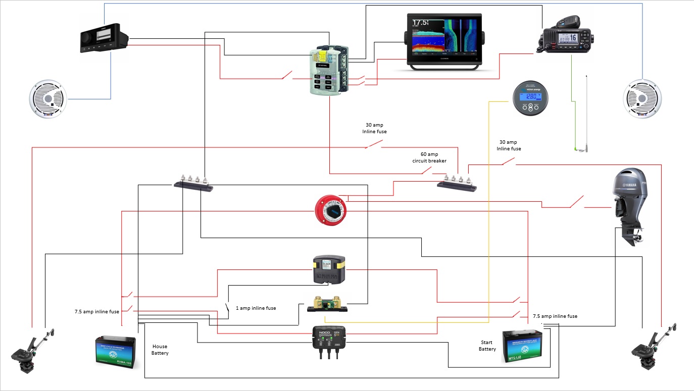
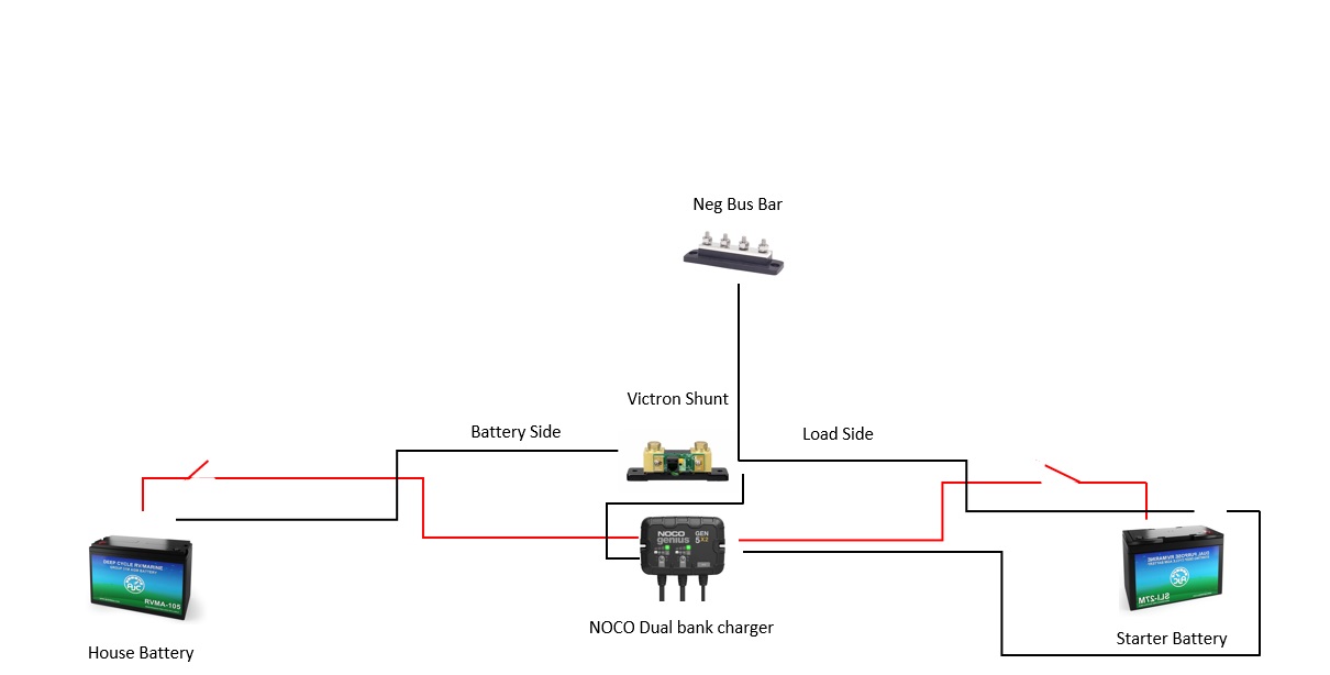
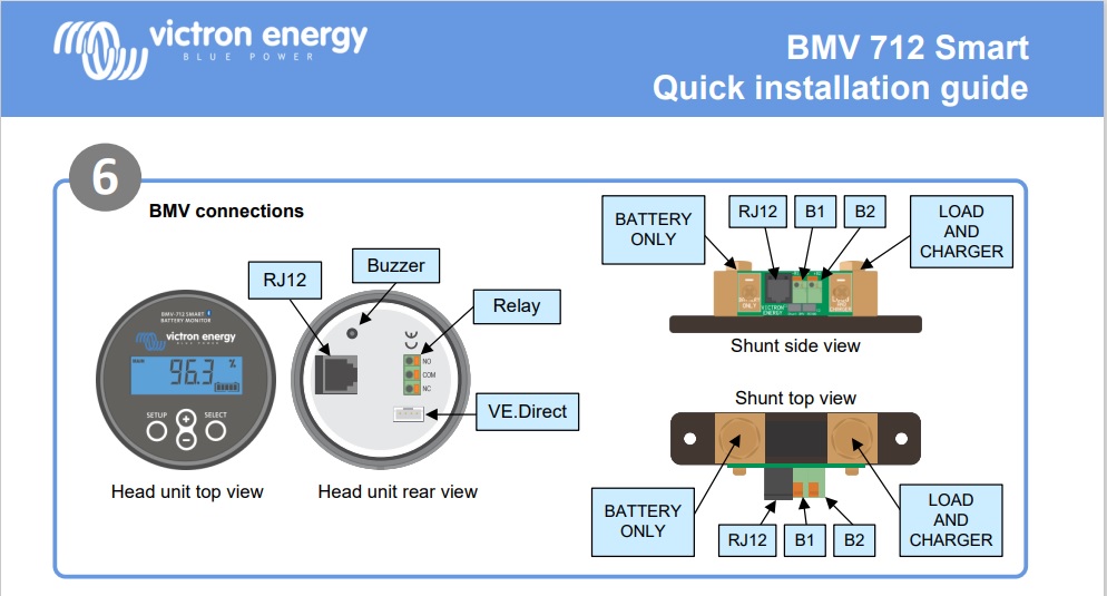
instructions but I had no plan to connect the NOCO charger to the shunt, only to both batteries + and - terminals as per the charger instructions. Is this correct?

0 Likes 0 ·
bmv-quick-guide.jpg (120.0 KiB)
Kevin Windrem avatar image Kevin Windrem zulu-55 commented ·

No. The ONLY thing that connects to the house battery negative is the battery side of the shunt. Most instructions for devices like the noco charger don't consider things like the BMV's shunt.

Again: the house battery negative connects ONLY to the shunt's battery terminal. Nothing on the shunt battery terminal either besides the battery. ALL negative connections to ALL other devices connect to the load side of the shunt.

If you still have doubts, I suggest you find a local installer.

0 Likes 0 ·
zulu-55 avatar image zulu-55 Kevin Windrem commented ·

Ok. Thank you for this answer. So, how do I connect the two batteries (house and starter)? Currently, they have a neg wire connecting the two. I'm assuming this is incorrect based on your answer?


It seems like I should instead make the only connection that they have in common be the neg bus? My only other thought is what I do with the ACR which requires connection to one of the grounds (starter battery as I understand). Otherwise, they are just connected to the + terminals of each battery.

I'm attaching a revised schematic based on your feedback for review.updated-schematic-bmv-consideration.jpg

0 Likes 0 ·
kevgermany avatar image
kevgermany answered ·

The negative connection between the batteries goes from the load side of the shunt to the negative side of the starter battery.

2 |3000

Up to 8 attachments (including images) can be used with a maximum of 190.8 MiB each and 286.6 MiB total.

kevgermany avatar image
kevgermany answered ·

Your updated schematic is still not going to work.

Should be:

House battery neg - shunt battery

Shunt load - neg Bus.

Starter battery neg - shunt load.

All other negatives to neg Bus.


Note: nothing except shunt battery to house negative.


There's another problem. Your charger connects the positives of the starter and house battery. I don't know the charger, but unless it's built to charge both types of battery at the same time and without allowing a cross current between them, Don't do it.


13 comments
2 |3000

Up to 8 attachments (including images) can be used with a maximum of 190.8 MiB each and 286.6 MiB total.

klim8skeptic avatar image klim8skeptic ♦ commented ·

@kevgermany Is this the right spot for the shunt?

shunt-placement.png


0 Likes 0 ·
shunt-placement.png (487.9 KiB)
kevgermany avatar image kevgermany ♦♦ klim8skeptic ♦ commented ·
As in X marks the spot?

Yes, yellow X is correct.


0 Likes 0 ·
zulu-55 avatar image zulu-55 commented ·

Thank you so much for helping me out with this. I truly appreciate it. I am going to have to contact NOCO to confirm that my dual bank charger to inquire about cross currents as I am not aware.

I updated my schematic again and believe it reflects what you last explained. version-30-schematic.jpg

0 Likes 0 ·
kevgermany avatar image kevgermany ♦♦ zulu-55 commented ·
Sorry, but NO.

You still have connections to the negative pole of the house battery bypassing the shunt.


0 Likes 0 ·
zulu-55 avatar image zulu-55 kevgermany ♦♦ commented ·

Oh, yes I see. I apologize for my lack of understanding. I've looked all over to find a schematic of a dual bank system with ACR, Shunt, Battery switch (Off, 1, 2, Combine) and a charger.


Here is another version where I eliminate the house battery ground that went direct to the neg bus instead of to the bus via the shunt. This better?version-40-schematic.jpg

0 Likes 0 ·
klim8skeptic avatar image klim8skeptic ♦ zulu-55 commented ·
You still have 2 negative wires on the house battery..

Look at my post from 21 hours ago.

0 Likes 0 ·
zulu-55 avatar image zulu-55 klim8skeptic ♦ commented ·

I'm sorry. I'm doing my best to understand. From the schematic, the only negative wire going to the house battery is from the battery side of the shunt. There is one more negative wire, but that is the charging wire. NOCO advises this should be installed in this matter. But, I don't know how experienced they are with shunts, etc.


I'm only clarifying because 1 of the 2 negative wires you mention that are on the house battery is the one leading to the shunt and the other is just for the charger.

On a side note, I've added a schematic with a BEP cluster which may clean up things a bit and would:schematic-with-bep-cluster.jpg

0 Likes 0 ·
Kevin Windrem avatar image Kevin Windrem zulu-55 commented ·
Regardless of instructions from other devices, the ONLY, repeat ONLY thing that connects to the house battery negative is the battery terminal of the shunt. No exceptions.


The shunt measures current in and out of the battery to determine state of charge. Anything connected to the battery will not be counted. So the charge provided by the charger will not increase house battery SOC, but obviously it IS increasing the SOC because it is pushing current into the battery.

0 Likes 0 ·
zulu-55 avatar image zulu-55 Kevin Windrem commented ·

Thank you. I apologize for the requirement for extra clarification but I do appreciate your help very much. So, it appears my dual bank battery charger setup is the issue. I'm having problems seeing how the dual bank battery charger would work properly on the house battery if I attach the neg lead to the load side but perhaps it would cause no issues? It's just that the other side of the charger will be connected direct to the starter battery which has a neg lead to the load side of the shunt and will then meet the neg lead that is normally attached to the house battery. I'm wondering if that will cause issues?

I'm attaching a smaller schematic describing what I think you're saying with just the shunt and the dual bank charger.shunt-dual-bank-charger.jpg


Do I even need a dual bank charger setup? I assumed I do with dual batteries but perhaps the BEP cluster switch makes it unnecessary as the VSR switch would help charge the house battery once the starter battery has been topped up?

0 Likes 0 ·
Kevin Windrem avatar image Kevin Windrem zulu-55 commented ·
I don't know the specific charger unit but feel you are always better keeping charging of two battery banks separate. I would only tie the two battery banks together in an emergency if your primary charging source is the Noco.


Your BEP cluster will tie the battery banks together when the engine is running which is OK as long as both battery banks are the same type. Directly connecting lead-acid and lithium battery banks isn't recommended, plus charging a lithium from an alternator could damage your alternator due to the litihium's much lower internal resistance. In this case, a DC-DC charger is a better solution because it will limit charging current protecting your alternator.
0 Likes 0 ·
zulu-55 avatar image zulu-55 Kevin Windrem commented ·
Great. Thank you. The batteries are of the same chemical makeup (one is a starter type and one is a house type though). So, with that being said, is the type of charger I have ok? Or should I be looking at just a single bank charger with the assumption that the VSR will activate and essentially ensure both batteries are being charged when my boat is parked in my driveway and the battery charger is plugged in?
0 Likes 0 ·
Kevin Windrem avatar image Kevin Windrem zulu-55 commented ·
I can't help you with an answer to this question since I don't know the behavior of the Noco charger or the VSR in your switch array. It is possible that the charger would produce a sufficient voltage to energize the VSR and tie the house battery to the starter battery and get charged that way. It is also possible that won't work, again depending on the charger output and VSR trigger points.


I would recommend a separate charger for your house battery so that it isn't limited by starter battery condition and it's charging sources. Not sure what your Noco charger will output but if it is about 10 amps per battery, it could take a very long time to charge your house battery. The alternator path MAY provide faster charging but that depends on it's output also.


0 Likes 0 ·
zulu-55 avatar image zulu-55 Kevin Windrem commented ·
Thank you for all of your help. I really appreciate it :-)
0 Likes 0 ·
kevgermany avatar image
kevgermany answered ·

There's a good diagram in the quick start guide. Number 11 is your starting point.

2 |3000

Up to 8 attachments (including images) can be used with a maximum of 190.8 MiB each and 286.6 MiB total.

Related Resources

Victron BMV battery monitors product page

Additional resources still need to be added for this topic

Victron temperature sensor disambiguation table - which product supports which sensor