question

yamlcase avatar image
yamlcase asked

Ground Relay on autotransformer with 3rd party inverter and grid input

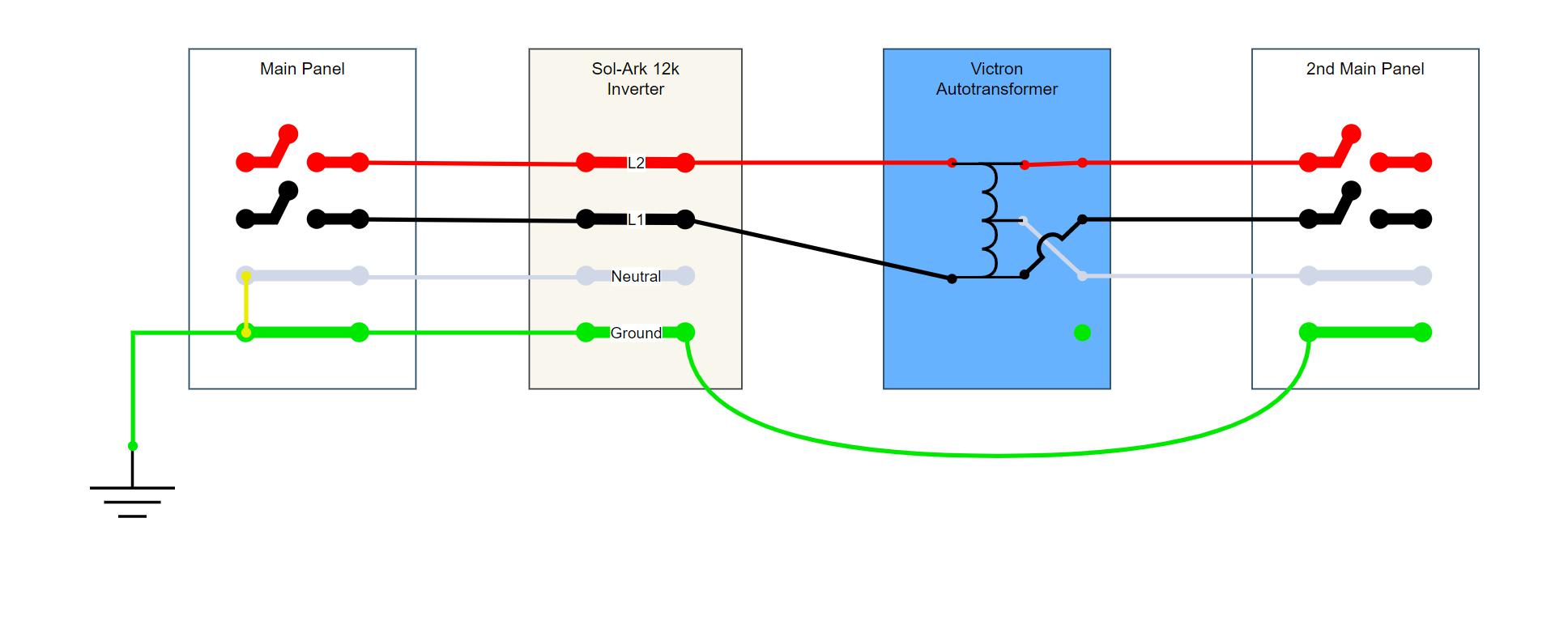
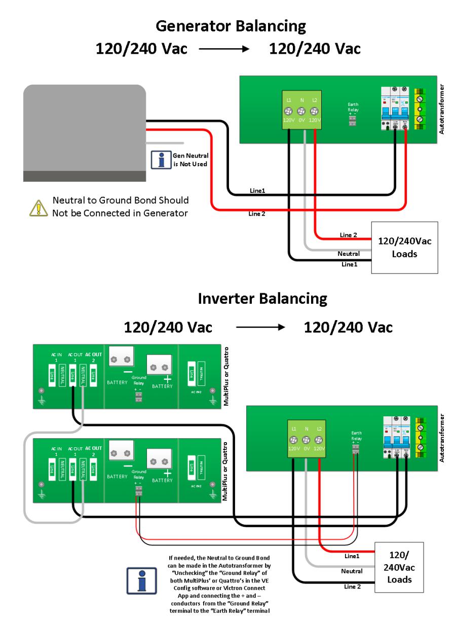
I am attempting to add the 100A autotransformer to my Sol-rk 12k setup for balancing the load (single-phase 240v). My setup most closely resembles 2.3.1 "Balancing a Generator or Stacked Inverters" in the manual except that my inverter supplies the load from the grid when sun's down and batteries are empty.

What's the recommended way to maintain that grounded neutral path back to my main panel at the service entrance since I'm creating a new Neutral at the AT? The manual isn't clear on how to utilize the ground relay with non-Victron inverters.

at-wiring.jpg

RelayGroundingAutotransformer
at-wiring.jpg (74.4 KiB)
2 |3000

Up to 8 attachments (including images) can be used with a maximum of 190.8 MiB each and 286.6 MiB total.

3 Answers
Kevin Windrem avatar image
Kevin Windrem answered ·

The autotransformer is creating a completely independent neutral circuit and should NOT to be bonded back to the service entrance. But you do need a neutral to safety ground connection at the output of the autotransformer. This connection provides a path for fault currents from one of the two hot legs in your "2nd Main Panel".


Edit: actually you are showing an ISOLATION transformer and what I said above applies to that type of transformer, not an autotransformer. An autotransformer would not be appropriate in your application.

2 |3000

Up to 8 attachments (including images) can be used with a maximum of 190.8 MiB each and 286.6 MiB total.

yamlcase avatar image
yamlcase answered ·

I made two changes to my diagram:

1. The autotransformer symbol has been corrected to avoid confusion. my cliparts didn't have autotransformer, so I originally subbed in a transformer symbol.

2. Bent the ground wire line to show AT not connected to ground.


@Kevin Windrem , thanks for the quick response. This is the 100A Autotransformer, not an isolation transformer.

"But you do need a neutral to safety ground connection at the output of the autotransformer"

I'm not sure how to properly ground the AT. There's the "Earth PE" terminal, but in the instruction manual it shows not to connect that to anything for my setup. This seems fishy to me, perhaps the diagram is wrong/incomplete? And how would I bond the neutral and ground at the AT output, in the 2nd Main Panel?

manual-231.jpg


manual-231.jpg (118.2 KiB)
2 |3000

Up to 8 attachments (including images) can be used with a maximum of 190.8 MiB each and 286.6 MiB total.

Kevin Windrem avatar image
Kevin Windrem answered ·

The rule is ONE and ONLY ONE safety ground to neutral connection in the entire system.

When you have a grid/shore power connection, the neutral to safety ground connection is made at the service entrance. The inverter's input relays close and their internal ground relays open.

Some generators make this neutral to safety ground connection internally. Some do not. When the generator does not make this connection internally, it must be made at the generator's output connections.

When the inverter is inverting (not using AC input), it's input relay opens and it's internal ground relay closes making the neutral to safety ground connection because the one made at the service entrance or generator no longer reaches the inverter outputs and the loads.. When the autotransformer is used on the inverter's outputs, the inverter's ground relays do not close, rather they command the one in the autotransformer to close.

There is no connection between the inverter output neutral and the neutral that go to the loads. This is because the autotransformer is creating a new neutral, allowing the two inverters to see the same load. Any load imbalance in the loads must be handled by the autotransformer.

2 |3000

Up to 8 attachments (including images) can be used with a maximum of 190.8 MiB each and 286.6 MiB total.

Related Resources