question

daschlichi avatar image
daschlichi asked

Quattro 48/15000 grounding Question for AC-In 1, 2 and AC-Out 1, 2

Dear Community,
I am about to wire my 3-Phase Quattro-15k-Setup and did not find the required answer in the Manual (also pictures googled... did not lighten things up yet)

Situation:

- ESS-Setup is planned with a coupled grid, but no Generator (yet, maybe in future)
- Grid delivers L1,L2,L3 and a PEN!
- PEN is connected to earth of the Building and splitted into PE and N from there onwards.

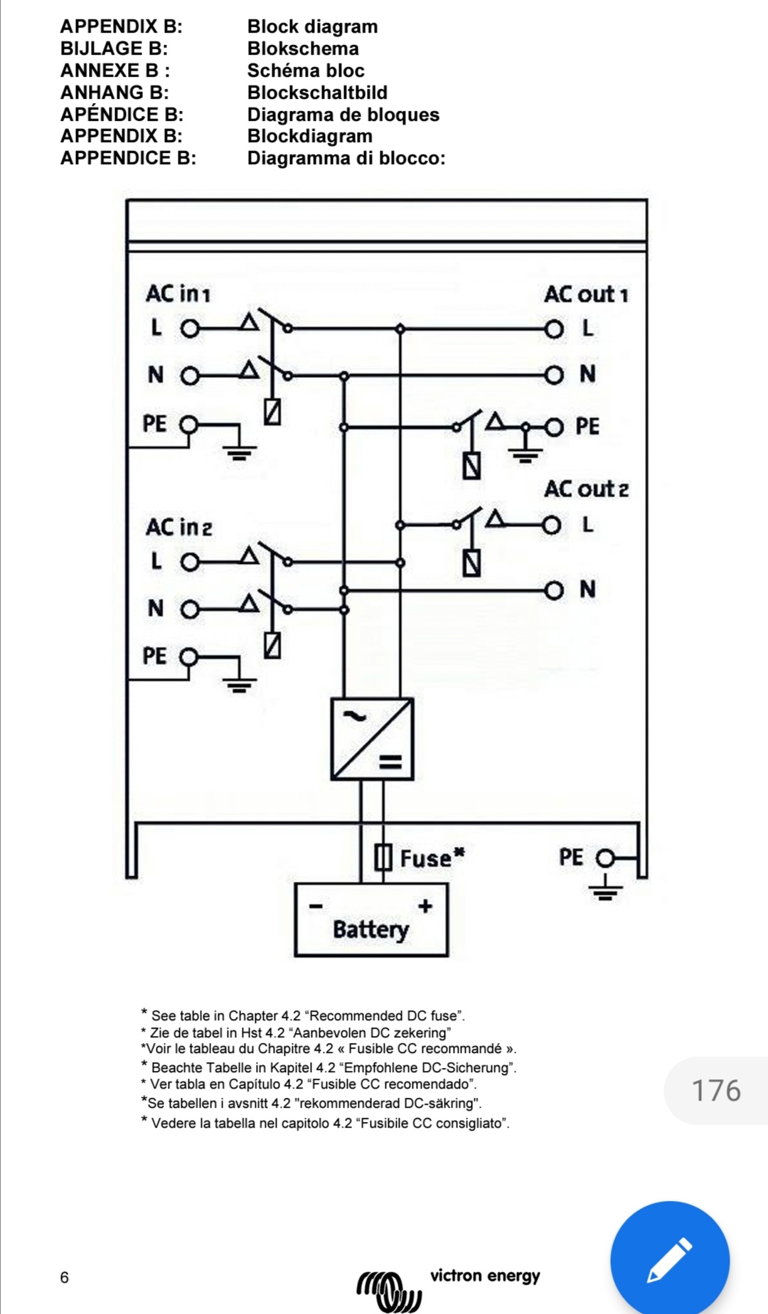
So far so good... from there onwards I want to connect my three Quattros 15K, but I am not sure how to wire the "four" grounds of each device (in total 12 Grounds-Connectors)...
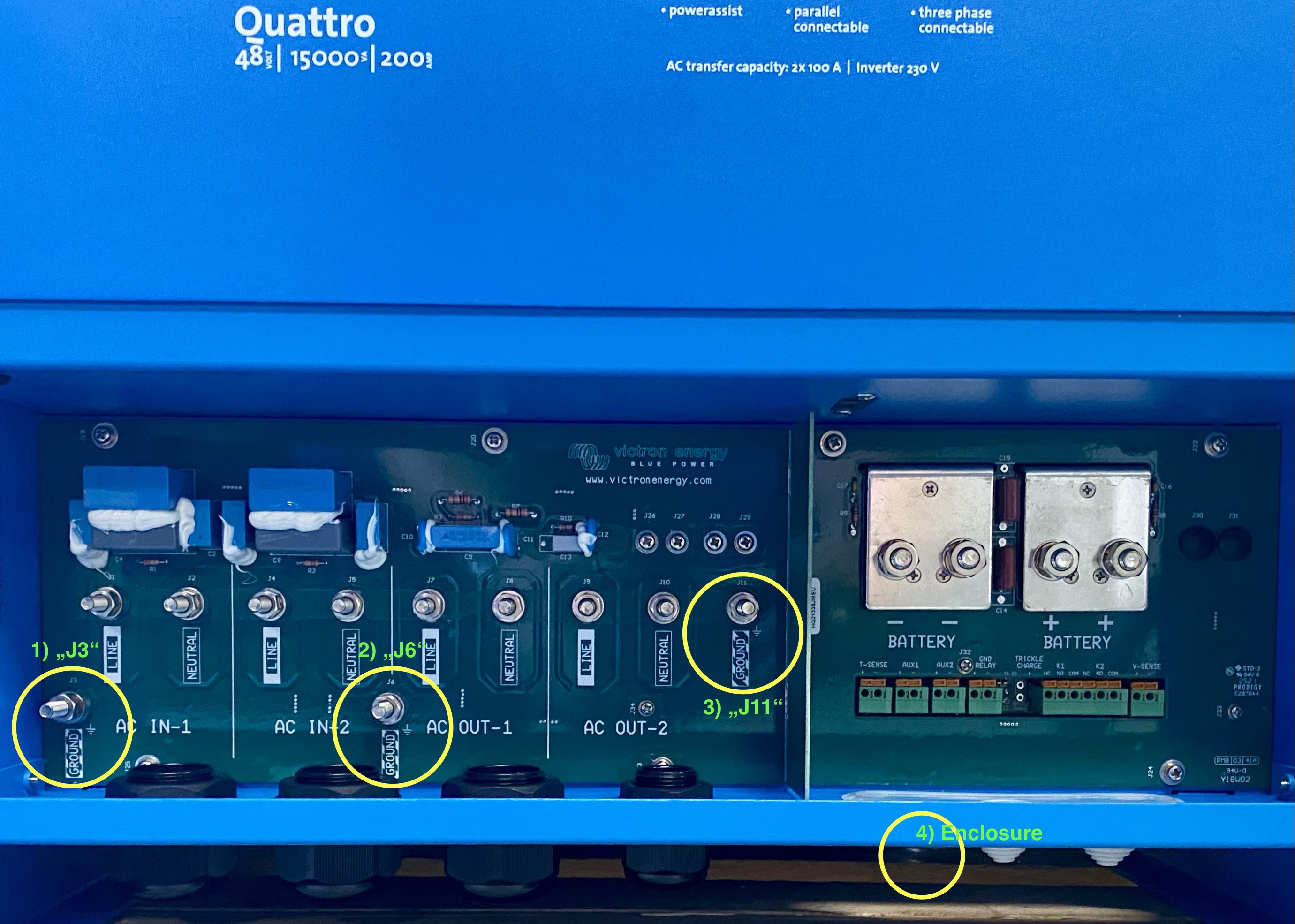
Each Q-15K has...

1) a Ground at Connector "J3"
Q: ? --> Only "Input" for AC-1 and with "Building-PE"

2) a Ground at Connector "J6"
Q: ? --> "Input" for AC In-2 or "output" for AC Out-1

3) a Ground at Connector "J11"
Q: ? --> "Output" for AC Out-2 ?

4) a Ground at the Enclosure underneath the connection-Area
Q: ? --> Most probably intended to be connected to the "Building-PE"?

Probably the essential Question is: Is PE somehow "switched" (and needs serial connection in which way), what kind of makes me nervous..., or can PE`s (1,2,3,4) just get connected in parallel? I don't get it yet... and I did not find a picture showing/explaining the Situation for the 15KVA-Model...

I probably need advice from someone understanding the internals of the device... 100%

img-0943.jpeg


Cheers, Daniel

MultiPlus Quattro Inverter ChargerwiringGrounding
img-0943.jpeg (1011.4 KiB)
2 |3000

Up to 8 attachments (including images) can be used with a maximum of 190.8 MiB each and 286.6 MiB total.

4 Answers
bbmz avatar image
bbmz answered ·

From my point of view you got it mostly right. As already mentioned you want a connection between N and PE to get RCDs working. It‘s common practice, that the active power station (usually the transformer in the grid) creates this bondage between N and PE.

Let’s assume a normal situation without a quattro. You get a L, N and PE and pass them through to your devices. If you add a quattro in this setup the grid goes to AC2 (in) and your loads on AC1 (out). This is why there is a shared connector on these two terminals.

The second type of loads gets it‘s PE on AC2 (out). In the case of an additional generator this power-source will be linked to AC1 (in). 4) is only for the metal housing and therefore for your safety in case of a device-failure.


Of course PE will always stay. Only N get‘s opened by the Quattro in case of a grid-failure. If your Inverter get’s now the power source it will create it’s own N from PE. If there is still a external power-source (generator) available it will of course use this N.

You can interpretate the linkeage between N and PE inside the Quattro as “the final option“ to get an N. Whenever there is another N available the Quattro will use this.


Summary: Technically it makes no difference where you connect which PE (but it will be a mess and probably not allowed by local regulations). Use AC1 (in) for a connection to a generator. Connect your grid on AC2 (in), your panel on AC1 (out) and/or AC2 (out) and use your building PE on the metal housing. The Quattro will always (and automatically) connects all PEs.

[There might be additional / regional regulations, that you have to use also a separate bus-bar to connect your grid PE with your building PE.]

2 |3000

Up to 8 attachments (including images) can be used with a maximum of 190.8 MiB each and 286.6 MiB total.

Alexandra avatar image
Alexandra answered ·

@daschlichi

PE and N internally are connected by a ground relay that closes when grid disconnects. This keeps RCDs and other safety systems working.

There is a simple drawing in the appendix of the manual.

screenshot-20220115-124143.jpg

When grid disconnects the PE/N from the board can no longer be used.

If you check with your meter you will find that there is continuity between some of the grounds there. With three phase I would advise getting a bit of physical help from a Victron dealer with the setup, especially if this is your first one. And have you done any of the training on Victron professional at all for the three phase?


2 |3000

Up to 8 attachments (including images) can be used with a maximum of 190.8 MiB each and 286.6 MiB total.

daschlichi avatar image
daschlichi answered ·

Dear Alex,

thank you for your reply, really appreciate that. I see, you are right (I now probably got the meaning of the schematics). Maybe it'll be good to try saying it in my words, to make sure I understood you correct.

>> The Quattro will disconnect both N and L1 from the Grid if the Grid fails. That is done, by opening a Relais (at AC-In-1 and AC-In2 left side of the picture) and in parallel closes a Relais (right top-side of pic) to pull the "open N" back to PE (of my House`s PE), right? --> But the picture essentially could be also interpreted, that the Relais (right top) also opens, so disconnects the AC-Out-N from the PE?

You wrote "When grid disconnects the PE/N from the board can no longer be used."

--> But why PE cannot longer be used? (N is clear to me now), but because it's no Boat or something my PE would always "stay"

Can I just put all "4 Grounds" in parallel to my House`s PE?

My Victron-Dealer is unfortunately 800km away.

Nope, no training, is there a free Webinar, like ESS (which I did)? Where can it be accessed?

Cheers, Daniel


2 |3000

Up to 8 attachments (including images) can be used with a maximum of 190.8 MiB each and 286.6 MiB total.

fay avatar image
fay answered ·

I was having some issue in this can anyone suggest me what should i do for it?

2 |3000

Up to 8 attachments (including images) can be used with a maximum of 190.8 MiB each and 286.6 MiB total.