Idea

Kevin Windrem avatar image
Kevin Windrem suggested

DC System GUI breakout

This is a half-baked idea and am looking for comments to help solve the issue of which components to display on the flow overview.

In the past, the GUI displayed status for a limited set of components: inverter/charger and PV charger (aka MPPT solar charge controller), then combined all other DC components in the "DC System" tile. The "grid parallel" overview provided space for additional components but focuses on AC coupled components.

Recent DC component additions (alternator, fuel cell, wind generator, AC and DC chargers, various DC loads, ...) present a challenge in displaying this information on the GUI. AC coupled components should also be displayed: PV inverters, AC loads on input and output. While not all of these components are likely to be included in any given system, There may be cases where GUI real estate is insufficient to display tiles for all component types.

Using the grid parallel flow overview as a start, I'm working on a layout the displays as many components as possible:

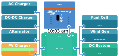
This view shows the possible DC component types:

screen-shot-2022-06-11-at-100337-am.png
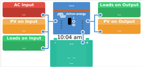
This view shows the possible AC component types:

screen-shot-2022-06-11-at-100410-am.png

In a typical system, it is likely to be sufficient space for all system components. Both of the following examples show all existing components.

screen-shot-2022-06-11-at-102531-am.png

screen-shot-2022-06-11-at-102653-am.png
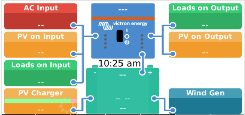
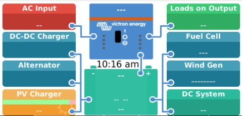
However, however some systems with mixed AC and DC components may require tiles be eliminated:screen-shot-2022-06-11-at-101355-am.png
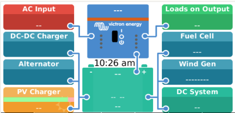
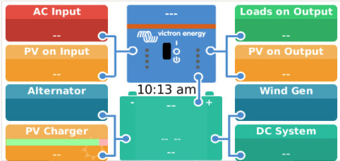
In this example, the AC charger, DC-DC charger and Fuel Cell tiles are not shown.

The newly added generic DC source and DC load device types create additional opportunities for conflicts and the need to eliminate components from the display.

A similar situation can occur if priority is given to DC components:

screen-shot-2022-06-11-at-101650-am.png

There is a desire to account for all power in the system so that if you add power from all shown components the result will be zero. For example, AC input plus inverter plus PV inverters should equal Loads on input plus Loads on output. DC System is currently a "catch all" for DC power. A similar catch all for the AC side of the system seems to be needed as well.

I currently have no solution for cases where sufficient GUI real estate exists to display all the AC and DC components. My guess is these cases may be rare but want to find a workable solution when they do occur.

One note: There is space for one additional tile on each side of the screen if temps and tanks are not show. So if this acceptable, I'd like to know that too.

I'm looking for your input.

Venus OS
2 |3000

Up to 8 attachments (including images) can be used with a maximum of 190.8 MiB each and 286.6 MiB total.

1 Comment

johanndo avatar image
johanndo commented

Hi Kevin,

That is a real problem to arrange all the items in a logical way, especially with all the available options and flexibility.

I can understand the idea of placing the battery and the inverter in the center, however, the battery is an edge device. there is no energy passing through from one side to the other, nor does the battery transform or pass energy in any way.

DC charger, alternator, PV charger on one side, Fuel cell, Wind .... and then DC System that can be bi-directional (unmonitored chargers and loads). And then another bi-directional system like the multi / Quattro - with separate energy flows makes no sense.

The reality is, all the sources feed the loads, and if there is a leftover, it goes into the battery, if the loads are higher, the battery feeds the loads as well. With 3 battery connections it is simply hard to guess is the battery charging or discharging (and there is no question about it, as the shunt knows really, there is only one single connection in reality).

I would not put the battery in the center, put it far away in a corner, to not deal with more than one connection, the center of gravity in the DC system is the bus bar where everything meets, and you have 2 of those at each side of the Quattro for the AC as well. I think even the Victron approach with the separate connection to the DC System is misleading at best.

If you want to compact the system, get rid of Multiplus, AC input and AC Output, make it one system with a bigger box and then it reflects the reality, you gain space for the satellite systems left and right of the quattro, you can still show the LEDs if you want to, but I doubt anybody is looking and understanding the LEDs without a manual, there is clear text in the box about the state anyway, the switch is obsolete, as it is not switching anything real, not shows the current position, the blue box has no information on the DC side either - so just a space consuming marketing visual.

Just a thought.

Nice mod by the way, quite useful and feature rich and well done with the installer and config pages.


Keep up the great work! Thumbs up.


P.S. You forgot the AC2 pass through output as third AC bus, sometimes used as dump device for generator / shore power

2 |3000

Up to 8 attachments (including images) can be used with a maximum of 190.8 MiB each and 286.6 MiB total.

Your Opinion Counts

Share your great idea, or help out by voting for other people's ideas.