article

Rob Duthie avatar image
Rob Duthie posted

Victron Raspi HAT

Hi All

Progress on the the Raspi HAT code name is called the Stetson as it does not follow the Raspi HAT

protocols, so i named it the Stetson due to space constraints in the PCB design with all the relays and plugs and sockets required etc.

It has the following inputs and outputs canbus PSU etc. All has being tested and confirmed working OK to date. as of version on Venus Ver 2.60. release and 2.66 candidate. All OK, For Later Version >2.66 there are issues that not all works as it used to. Update some progress with new version >2.66 to 2.80.19

As in Bold all working again except the VE direct I2C ports USB is OK.

2x Temperature using the the LM335 devices: Working OK on Ver 2.80.24 Added 4 temps

3x Tanks resistive: Working OK on Ver 2.80.24 Added 4 tanks

5x Digital Hi ports all isolated with pulse counting etc: Working OK on Ver 2.80.24

1x Canbus port Working: OK on Ver 2.80.24 on USB and SPI ports

2x VE Direct ports: Not sorted yet with software USB OK but

6x relays outputs: Working OK on Ver 2.80.24

1x PSU from 10 to 55vDC to be upgraded to higher voltage 75vDC

Attached schematic for you information.

Options for the future: buzzer indicator, code is there just need some time to redirect the code to the right GPIO pins to make it work.

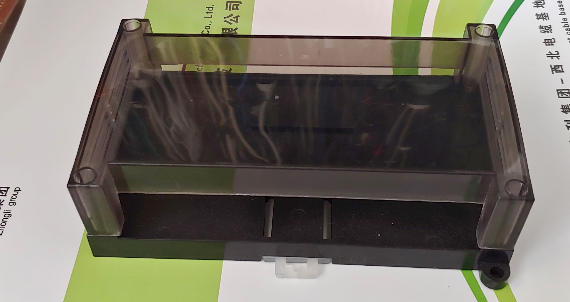
The PCB design is almost complete, it will mount in a din rail enclosure and a main 40 pin ribbon cable will connect between the Raspi and the Stetson. Updated PCB files with VE direct ports.

Update 20/10/2021 Schematic updated to full 6x relays on board and new PSU module and the 4x Tank and 4x Temp sensor inputs. Digital input circuit change, PCB is done, BOM done.

Victron Raspi Hat.pdf

Victron Raspi Stetson.pdf

Regards

Rob D

NZ

Victron Raspi Hat.pdf

Victron Raspi Stetson.pdf


Raspberry Pi
146 comments
2 |3000

Up to 8 attachments (including images) can be used with a maximum of 190.8 MiB each and 286.6 MiB total.

jimmyendt avatar image jimmyendt commented ·

Hello,

I've searched this forum thoroughly, looking for upgrades on my raspberry pi venusos installation. This raspberry pi HAT seems awesome. I've already contacted Rob Duthie

He told me there are some people making these awesome boards? Is there a way to buy a board somewhere? Would like so very much!


Thanks in advance,

2 Likes 2 ·
Mark avatar image Mark commented ·

Thanks Rob.


1 Like 1 ·
s-exley avatar image s-exley Mark commented ·

Hi Mark,

I've sent you an email, if there's anything I can do to help, let me know.

Cheers
Simon

0 Likes 0 ·
Show more comments
Vincent Royer avatar image Vincent Royer commented ·

Looks awesome. Can I make some suggestions?


- 2 x CAN, isolated, like the Octo-GX, using RJ-45 connectors, or a board-mounted dip for termination resistor


- Ideally a whole other isolated CAN that can be a different speed (for can-bms and can-xxx at the same time)

- ve-direct ports that dont peel off the board when you look at them wrong like the ones on Octo-GX

- PSU with a +12V output as well for integration w/ the relays

- smd LEDs on the board at each input / relay output to show state

- if you can put all connections on one edge, otherwise it doubles the size of the install

- don't use spring connectors, use screw types and oversize them


0 Likes 0 ·
Rob Duthie avatar image Rob Duthie Vincent Royer commented ·

Hi Vincent

Answers in bold

- 2 x CAN, isolated, like the Octo-GX, using RJ-45 connectors, or a board-mounted dip for termination resistor. I will look into a dual isolated depends if another interrupt is required or not. I have already a 120 ohm jumper on board. I am using hard wired screw header connector

- Ideally a whole other isolated CAN that can be a different speed (for can-bms and can-xxx at the same time) as above, i have testing the canbus with a pylon US2000 with the USB port and direct canbus port both work OK, it will need some extra code to add the can0 and can1 ports? so far it is bullet proof with just can0 running.

- ve-direct ports that dont peel off the board when you look at them wrong like the ones on Octo-GX:Only have one serial port to work with for the VE direct port i will add a isolated serial port to suit RJ45 connector OK or screw terminal?

- PSU with a +12V output as well for integration w/ the relays: Can be added means another DC to DC converter PSU has to added to what current are you looking at 1Amp?

- smd LEDs on the board at each input / relay output to show state: Yes i was thinking about that and now will add into the design.

- if you can put all connections on one edge, otherwise it doubles the size of the install: I have used a dual edge Din rail enclosure to keep the PCB small, enclosure 125x90mm. other wise i will have to use a lot longer enclosure, due the size on the connectors i am using, i could use micro connectors, but is tight for the larger wires sizes there are trade offs.

- don't use spring connectors, use screw types and oversize them: I have used plug and header socket with spring terminals as standard. which take the larger wire sizes. These are duel in line to save space for the Analog and DIO ports the relays are screw terminal header plugs.

0 Likes 0 ·
Vincent Royer avatar image Vincent Royer Rob Duthie commented ·

Why screw connectors for CAN? you should stay with the Victron standard of RJ45. It eliminates user headaches figuring out their own can cables. Also, when you connect it to Victron equipment, you will have to cut an RJ45, leaving you with tiny 26AWG wires which won't reliably connect to your screw terminals. Use RJ45!

For Ve-direct maybe the best way is to implement direct serial input, its 5V ttl iirc, so you'll have to level shift it. But I wouldn't omit it entirely from your design.

For the 12V out, you don't need a lot of current, 1A is fine, but something with built in flyback so we can hook it up to a bigger contactor. Some designs offer the ability to switch the relay COM to a 12V source (I prefer a separate output). Can use it to drive a bigger status LED or even a small fan.

For the terminals, I've never used a spring terminal I didn't wish was a screw terminal instead. There just doesn't seem to be a situation where they are better.


Are you using one of those little white Din-rail RPi cases by phoenix contact?


0 Likes 0 ·
Rob Duthie avatar image Rob Duthie Vincent Royer commented ·

Why screw connectors for CAN? you should stay with the Victron standard of RJ45. It eliminates user headaches figuring out their own can cables. Also, when you connect it to Victron equipment, you will have to cut an RJ45, leaving you with tiny 26AWG wires which won't reliably connect to your screw terminals.Use RJ45! I use boot laces with no problems There are other applications for other lithium BMS battery connections that don't use RG45 connectors i will consider it. Have to consider BYD and Pylontech and other manufactures as well plus the other DIY user of Tesla and Nissan leaf batteries etc.

For Ve-direct maybe the best way is to implement direct serial input, its 5V ttl iirc, so you'll have to level shift it. But I wouldn't omit it entirely from your design. : Done, levels shifted and isolated. Needs to be tested i am using pins 8,10 on the the raspi GPIO which are the UART.

For the 12V out, you don't need a lot of current, 1A is fine, but something with built in flyback so we can hook it up to a bigger contactor. Some designs offer the ability to switch the relay COM to a 12V source (I prefer a separate output). Can use it to drive a bigger status LED or even a small fan. Done easy to add just more cost and will have to use a larger PCB and Din rail enclosure.

For the terminals, I've never used a spring terminal I didn't wish was a screw terminal instead. There just doesn't seem to be a situation where they are better. Had no issue to date with spring terminals, they are used only on the Analog and digital inputs, due to space constraints etc.


Are you using one of those little white Din-rail RPi cases by phoenix contact?

No, too expensive i am using a Chinese version with a tinted grey clear top Note: With the changes required the design of the PCB has blown out. So will have to upgrade the enclosure to the next size up. 150x90mm.

Regards

Rob D

NZ


0 Likes 0 ·
gc50 avatar image gc50 Rob Duthie commented ·

Hi Rob

Where can I get one of these boards

I am in Motueka NZ

Been looking for a canbus port for the Venus RPI

Which has been running on VRM for 7 years now

Want to connect my 150/70 Ve.Can MPPT

Cheers

Gil


0 Likes 0 ·
ofernander avatar image ofernander Rob Duthie commented ·

Did this ever get produced or finalized? I'd love to buy one or obtain the files so I can have a few made for myself.

0 Likes 0 ·
Rob Duthie avatar image Rob Duthie ofernander commented ·

Hi

Send me email address raduthie@gmail.com

0 Likes 0 ·
nebulight avatar image nebulight commented ·

Awesome! Sign me up!

0 Likes 0 ·
Rob Duthie avatar image Rob Duthie commented ·

Hi All

Note: Updated Schematic file with all the extras included.

VE direct port x1

Can bus port x1

LED relay indicators x4

Extra 12 V independent PSU for use with relay outputs if required.


Regards
Rob D

NZVictron Raspi Hat.pdf

0 Likes 0 ·
nzmikec avatar image nzmikec Rob Duthie commented ·

Looks awesome! Im keen to build one of these up. @Rob Duthie have you had PCB's built? Do you plan on selling a kit or sharing the greber files? JLBPCB have a build service ive used in the past, not sure if they will have the chips in your design tho.

0 Likes 0 ·
Rob Duthie avatar image Rob Duthie nzmikec commented ·

Hi

Yes i will be sharing, and selling the main PCB and din rail mounted enclosure all the parts are common nothing odd ball.

Just finalization of the PCB design.

I use Altium for PCB work, so i work in pcbdoc file format.


Regards

Rob D

NZ

1 Like 1 ·
Rob Duthie avatar image Rob Duthie commented ·

Hi

Updated schematic due small change in on of the spi ports select port CS1 not being assigned to the correct device.

Victron Raspi Hat.pdf

Regards

Rob D

NZ

0 Likes 0 ·
victron-raspi-hat.pdf (947.3 KiB)
laurenceh avatar image laurenceh Rob Duthie commented ·

Rob
do you know the answer to my separate thread about getting dbus-adc directory for the Rpi I have a card with the chip on ( and driver I think) but need this directory to get Venus os to recognise it.

Thanks

0 Likes 0 ·
Rob Duthie avatar image Rob Duthie laurenceh commented ·

Hi Laurence

Have you installed the updated file dbus-adc into /opt/victronenergy folder

Then runs these commands to activate, this is all that is required to make the ADC to work.

install dbus-adc file into /opt/victronenergy/ // (install via Bitvise the file ( dbus-adc )
chmod 755 /opt/victronenergy/dbus-adc/start-adc.sh
chmod 755 /opt/victronenergy/dbus-adc/dbus-adc
chmod 755 /opt/victronenergy/dbus-adc/service/run
chmod 755 /opt/victronenergy/dbus-adc/log/run (need to add a folder called log and a file called run inside it) if missing?
touch /var/log/dbus-adc (sets time stamp of the file or created one)
ln -s /opt/victronenergy/dbus-adc/service /service/dbus-adc


Regards

Rob D

NZ

0 Likes 0 ·
laurenceh avatar image laurenceh Rob Duthie commented ·

Rob

I know I need to do these things what is puzzling me is where to find the dbus-adc files required, so explicitly :

What do I download from where?
if they are part of larger image how do I extract the files required?

Thanks

0 Likes 0 ·
Rob Duthie avatar image Rob Duthie laurenceh commented ·

Hi

You have the mcp3208-overlay.dtb installed in the over lays folder file?

https://github.com/aaronsb/victronvenussupport/blob/master/mcp3208-overlay.dtb


The file ADC dbus file wont upload to this site, can be found here.

https://www.dropbox.com/sh/gd80g2u048ls0h3/AAAeY2HSD05qb1W3CkBS64dva?dl=0


0 Likes 0 ·
laurenceh avatar image laurenceh Rob Duthie commented ·

Excellent and thanks.

I’m out today should be able to try tonight.

0 Likes 0 ·
laurenceh avatar image laurenceh laurenceh commented ·

Rob

all installed and worked fine need to:

1) do some hardware tests tomorrow

2) contact my tank sender supplier about feasibility of using voltages from the senders I am currently using as inputs

3) learning how to edit the pages screens.

0 Likes 0 ·
Rob Duthie avatar image Rob Duthie laurenceh commented ·

Hi

That,s good to hear.

The tank senders are resistive loads not voltage output as such.

The tank senders are 0-180 ohms or 240-30 ohms.

The page screens can be set from the tank setup menu to be as fuel, oil water, sewage etc.


Regards

Rob D

NZ

0 Likes 0 ·
rvoosterhout avatar image rvoosterhout Rob Duthie commented ·

I have another question about this. I uploaded the dbus-adc folder using Bitvise and ran the commands.

I have a question about the following command:

chmod 755 /opt/victronenergy/dbus-adc/log/run                         
(need to add a folder called log and a file called run inside it) if 
missing?

I noticed that the dbus-adc folder in drobox, has the log folder and run file inside the /dbus-adc/service folder. Do I still need to copy the log folder to the dbus-adc folder so that the command above actually works? Or do I need to change the command to:

chmod 755 /opt/victronenergy/dbus-adc/service/log/run

My 2nd question is that I also uploaded the mcp3208-overlay.dtb file to the /u-boot/overlays folder, do I need to change anything there or is that all I need to do?

Question #3, do I need to change anything to the config.txt inside the /u-boot folder?

0 Likes 0 ·
Show more comments
Show more comments
mihair avatar image mihair commented ·

Hi Rob,


May I suggest not using SI8422 plus MCP2551? They are not so reliable parts in ICS environment. Instead please use ISO1050 from TI

0 Likes 0 ·
Rob Duthie avatar image Rob Duthie mihair commented ·

Hi

The ICS stands for industry control systems? more robust device.

What is wrong with the MCP2551 device? this is what i have used and have no problems to date connecting to a Pylon tech BMS systems etc.

So you saying to use just the one combined chip with isolation and canbus, which would make sense and one less part to wire up etc.

OK i will take your advise, re do the schematics and PCB, and up load later.


Regards

Rob D

NZ

0 Likes 0 ·
mihair avatar image mihair Rob Duthie commented ·

Nothing's wrong with MCP2551 itself but your implementation has the can converter as last device on the bus, after the isolator. In case of voltage spikes it could be easily damaged or communication perturbed


From the ISO1050 doc:

"

As a CAN transceiver, the device provides differential

transmit capability to the bus and differential receive

capability to a CAN controller at signaling rates up to

1 megabit per second (Mbps). The device is designed

for operation in especially harsh environments, and it

features cross-wire, overvoltage and loss of ground

protection from –27 V to 40 V and overtemperature

shutdown, as well as –12-V to 12-V common-mode

range

"

0 Likes 0 ·
Rob Duthie avatar image Rob Duthie mihair commented ·

Hi

Yes taken note on this now, thanks.

0 Likes 0 ·
pau1phi11ips avatar image pau1phi11ips commented ·

Sounds awesome, gonna be better than the CC GX at this rate!

0 Likes 0 ·
rvoosterhout avatar image rvoosterhout commented ·

Hi Rob,

This looks amazing! Do you have any updates on the Stetson? I would love to use this, but I have no experience with PCB ordering.


Rick

0 Likes 0 ·
rvoosterhout avatar image rvoosterhout rvoosterhout commented ·

Awesome Rob, i'm looking forward to it!

0 Likes 0 ·
Rob Duthie avatar image Rob Duthie rvoosterhout commented ·

Hi All

Just an update on the stetson, we could have up to 6 output relays if required (Mark UK) has tested it to 8 but some GPIO clashed with the canbus control, but i need to confirm as i am running out of space to to fit them all, unless i upgrade the PCB design and case i had in mind to use, as the case was a din rail mount type with a cover 150x90x45 etc.

As per photo attached.

OK updated PCB and Schematic to have 2x extra relays they are named Aux 1 & 2 as they control a 12v external relay coil only, due space constants etc. They have a indicator LED each and an output current of 500mA max.

Confirmed we have 6x relay outputs all working OK now. An you can name as required via WinSCP. If some one wants the files just email me and i will send the required files to make the 6 relays work, just a matter of copy and paste into the Venus folders.


Victron Raspi Stetson.pdfVictron Raspi Hat.pdf

0 Likes 0 ·
captain-nemo avatar image captain-nemo commented ·

Very nice initiative! I assume te RPI is powered via the Stetson board, I know on RPI there is a fuse to protect against overvoltage etc. located at the micro USB connector on the RPI, powering over the RPI header bypasses this fuse. Would this be useful to add a fuse on the stetson on the 5v pin that powers the RPI?

Oh, and what about gps? Is it possible to add another hat fo GPS or would USB GPS be the only option?

Cheers,

Menno

0 Likes 0 ·
Rob Duthie avatar image Rob Duthie captain-nemo commented ·

Hi Captain Nemo

Thanks for the feed back, looking at extra power protection etc. I do have over voltage protection built in, and a USB port which can be feed to the raspi directly etc. As the unit has dc to dc power regulators converters, external fusing is required as like the CCGX units have done.

Also there is a 12v 1amp feed output for the external relays coils etc.

The GPS works already by plugging in a USB GPS receiver type # BU-353S4 and these work very well with no issues to date.

Updated files below.


Regards

Rob D

NZ

Victron Raspi Hat.pdfVictron Raspi Stetson.pdf

0 Likes 0 ·
captain-nemo avatar image captain-nemo Rob Duthie commented ·

Hi rob,

Thanks for the feedback!
what would be the next step to make this board? Is it ready to use or does it need more testing? If it needs testing, can I help? For pcb making a gerber file would do, but soldering Smd it not my strongest suit. I know some local pcb companies that I used for making pcb’s for my company. Silk screen etc are also needed in this case.

Please advice on what I can do.

Br

Menno

0 Likes 0 ·
Rob Duthie avatar image Rob Duthie captain-nemo commented ·

Hi

The PCB you can make your self if required once i release the Gerber files etc.

Hand soldering will be slow and time consuming etc. The PCB will have all the silk screens in place etc.

So just going threw final checks and BOM etc now.

Regards

Rob D

NZ

0 Likes 0 ·
Rob Duthie avatar image Rob Duthie commented ·

Hi

Their have being some changes we have now 6x relay outputs and added a USB port for power only. And a 12v external supply for relay coils to use.

Victron Raspi Stetson.pdfVictron Raspi Hat.pdf

0 Likes 0 ·
captain-nemo avatar image captain-nemo Rob Duthie commented ·

Looks ok to me, don't see any issues.

0 Likes 0 ·
Show more comments
matt-kay avatar image matt-kay commented ·

Hi @Rob Duthie any update on when this will be available to purchase?

0 Likes 0 ·
Rob Duthie avatar image Rob Duthie matt-kay commented ·

Hi Matt

Yes the PCB design is done i have a person in the UK who is getting some made to test.

As i have being busy working on other jobs and projects and have put it to one side until i getting PCB costing done etc.

I am am based in New Zealand.

The design is open source, you are welcome to use files to get some made.

I will up an link to down load etc.

Rob D

NZ

1 Like 1 ·
padigree avatar image padigree Rob Duthie commented ·

Hey, any news? Would be glad to get the files so I can order a board with some other pcbs I have to order :)

0 Likes 0 ·
Rob Duthie avatar image Rob Duthie padigree commented ·

Hi


Send me a email and i will send the files.

Regards

Rob D

NZ

0 Likes 0 ·
padigree avatar image padigree Rob Duthie commented ·

Thank you! But I can't find any email adress on your profile, neither anywhere on your posts, nor on the web :/


0 Likes 0 ·
Rob Duthie avatar image Rob Duthie padigree commented ·
0 Likes 0 ·
myhome avatar image myhome Rob Duthie commented ·

Hi,

this is a very intresting project.


Im from Germany, is there a possibility to buy one or two PCBs?


Regards

Johannes

0 Likes 0 ·
Rob Duthie avatar image Rob Duthie myhome commented ·

Send me a email address so i can send the files.

0 Likes 0 ·
myhome avatar image myhome Rob Duthie commented ·
0 Likes 0 ·
Show more comments
s-exley avatar image s-exley commented ·

Hi Rob,

I'm also in the UK and am interested in getting one of these hats, I'm quite happy to buy one or make one depending on what's easiest for you, if that was possible.

Cheers

Simon


0 Likes 0 ·
Rob Duthie avatar image Rob Duthie s-exley commented ·

Hi

There is guy called Mark Bramfield who has my design there and he is getting some PC done.


Regards

Rob D

N Z

2 Likes 2 ·
s-exley avatar image s-exley Rob Duthie commented ·

I don't suppose you have contact details for him or is he on here?

0 Likes 0 ·
Rob Duthie avatar image Rob Duthie s-exley commented ·
2 Likes 2 ·
nick-peck avatar image nick-peck commented ·

also interested in purchasing one of these

0 Likes 0 ·
p0lar avatar image p0lar commented ·

how do we get one?

0 Likes 0 ·
Steve avatar image Steve commented ·

Thank you very much for all this research and development !!! I too would be interested in buying one !!! I am from Canada. You can contact me at: teardrop-quebec@hotmail.com


Thank you !!!

0 Likes 0 ·
Rob Duthie avatar image Rob Duthie Steve commented ·

Hi Steve

As you have a hotmail account it gets blacklisted.Victron Raspi Hat.pdfVictron Raspi Stetson.pdf

As attached information. i did have a guy in the UK getting some made, not sure were he is at.
As you can see by the schematic to what it can do etc.

0 Likes 0 ·
Steve avatar image Steve Rob Duthie commented ·

Out of curiosity, is this a guy named Mark (Spunky), (IVEA VAN) from the MBC Off Grid Solution site ??

MBC Off Grid Solution

If so, I am very happy to have the plans for the Stetson hat in hand.

See the pictures !!a2d-1.jpga2d.jpg

If not, too bad Lollll !!!

The A2D module is sold by MBC 150 GBP and the kits are sold for 300 and 400 GBP.

0 Likes 0 ·
a2d.jpg (35.2 KiB)
a2d-1.jpg (40.9 KiB)
Mark avatar image Mark Steve commented ·

Hi Steve

Yes Rob's is far more advanced than the one I made with robs help.

As you will see there is a lot of work goes into this and Rob has put a lot of time and effort into it. And then gives the plans free of charge to people.

The unit on MBC website is for people who don't want to make it or spend the time making it from components.

The cost is for making it and supplying it as a plug and play unit.

I'm sure you will see what goes into now you have the plans to make one.

Thanks

Mark

1 Like 1 ·
Steve avatar image Steve Mark commented ·

Hi Mark,

unfortunately I don't think I could make this module by myself as I don't have enough electronics knowledge to be able to do it on my own. I'll have to find another solution or someone who can do it for me.

As for the turnkey systems that you offer, it is very interesting but with the value of the Canadian currency at the moment I will have to pay almost double the asking price in GBP which becomes less interesting on the monetary side, because for the same price here I could have the Victron screen and the Cerbo GX, which is nonsense to go in that direction. I'm in a dead end and can't find a suitable solution.

0 Likes 0 ·
Rob Duthie avatar image Rob Duthie Steve commented ·

Hi Steve

Me and Mark are working on a solution which will have enhanced features and is plug and play design with the raspi units and our raspi HAT called a stetson. as per file below as you can see on the schematic at what it can do etc.

Rob D

NZ

Victron Raspi Hat.pdfVictron Raspi Stetson.pdf

1 Like 1 ·
Steve avatar image Steve Rob Duthie commented ·

Hello Rob, Hello again Mark,


Do you believe that PCBWAY could be able to create and assemble your prototype from your plans? This is the best alternative I have found so far to be able to produce and have your Stetson hat PCB!

0 Likes 0 ·
Rob Duthie avatar image Rob Duthie Steve commented ·

Yes they could, the only couple of parts i get from Ali express is the DC to DC PSU modules which are soldering directly onto the PCB.

The rest is standard components, I have only tested the basic prototype and not constructed and fully tested the whole PCB, as i have being busy doing other projects and work. I will contact a PCB manufacture to see what is cost to make a set of test PCB up.

Regards

Rob D

NZ

0 Likes 0 ·
Steve avatar image Steve Rob Duthie commented ·

I sent the plan you provided me to request a quote. As soon as a response I will get back to you with the information.

Well as I was enthusiastic to be able to produce the "Raspi Stetson Hat" I did not realize that I was missing a very important element to carry out the project. I was brought back to reality pretty quickly by PCBWay lollllll. I absolutely need the "GERBER" files !!!! Without them, too bad no PCB !!!

I realize that there is still a long way to learn Lollllll !!!!!!

Steve

CND

0 Likes 0 ·
Show more comments
Rob Duthie avatar image Rob Duthie Steve commented ·

Hi

Yes and that is not what i have mine is more advanced complete PCB design with din rail enclosure etc like the GX and Cerbo model design.

0 Likes 0 ·
Mark avatar image Mark Rob Duthie commented ·

Hi Rob

I wondered how long until the website appeared on here. I've not been about much my apologies. I will call you tomorrow.

Cheers

Mark

0 Likes 0 ·
Rob Duthie avatar image Rob Duthie Mark commented ·

Hi

We need to talk business here? getting very busy with inquires etc.

I have sold so much Victron gear lately its not funny.

0 Likes 0 ·
Mark avatar image Mark Rob Duthie commented ·

Definitely mate

I will ring you tomorrow.

Glad your busy.

Cheers

0 Likes 0 ·
moehn avatar image moehn Mark commented ·
Hello Rob

Thank you for your work in creating the circuit diagram.

I'm from Germany.

Would it be possible to get the file to make a circuit board for me?

My E-mails: d-michaelis@gmx.net

greetings 
Dirk
0 Likes 0 ·
Rob Duthie avatar image Rob Duthie moehn commented ·

Hi Dirk as per email i sent you direct.

Updated schematic to be updated to a dual isolator chip Victron Raspi Hat.pdf

0 Likes 0 ·
victron-raspi-hat.pdf (693.2 KiB)
Show more comments
Markus avatar image Markus Rob Duthie commented ·

i miss the diode paralell to the relais coils, ULN2003ADR has no diode inside an can get demage by switsh off relais


0 Likes 0 ·
Kevin Windrem avatar image Kevin Windrem Markus commented ·

The TI data sheet for the ULN2003 does show a kick-back diode.

1 Like 1 ·
Markus avatar image Markus Kevin Windrem commented ·

i have looks are right for the ULN2003


0 Likes 0 ·
aph avatar image aph commented ·

Hi all,

I was wondering if anyone has had a few of this awesome Victron hat produced and would be willing to sell one to me?

I am sure there are some more fellows here in the forum who would buy one.

CU,

Arne

0 Likes 0 ·
Rob Duthie avatar image Rob Duthie aph commented ·

Hi Anre

Yes had to add some extra analog inputs which i have not finish yet.

Regards
Rob D

NZ

0 Likes 0 ·
alan avatar image alan Rob Duthie commented ·

Is the hat fully functional with VE.Direct devices?

0 Likes 0 ·
Rob Duthie avatar image Rob Duthie alan commented ·

Hi Alan

Yes it is, for USB and Serial ports, had some of the code changed to allow for 2x VE direct ports.

Regards

Rob D

NZ

0 Likes 0 ·
aph avatar image aph Rob Duthie commented ·

All right, let’s switch to pm. Will you contact me via mail? Adress is aph(at)bearbo,de

cheers, Arne

0 Likes 0 ·
Rob Duthie avatar image Rob Duthie aph commented ·

Hi Arne

?

0 Likes 0 ·
aph avatar image aph Rob Duthie commented ·

Hi Rob,


my understanding was, that you had a ready to use Victron rpi hat for sale. Wanted to negotiate the details. Am I wrong with that assumption?

Cheers Arne

0 Likes 0 ·
Rob Duthie avatar image Rob Duthie aph commented ·

Hi Arne

Yes i did but had a few request to upgrade to more analog inputs total of 8x 4x tanks and 4x temp and add 2x VE diect ports and more relay otputs so it has slowed progress i am looking a putting a line in the sand, as i can't expand much more etc. And it holds up the project.

Regards

Rob D

NZ

0 Likes 0 ·
5teve avatar image 5teve Rob Duthie commented ·

@Rob Duthie Apart from 2.7 breaking everything, do you have any kind of idea when the line is being drawn and when production may commence? I'm just replacing some senders and would love to get rid of the gauges.. but I have to replace the gauges too because of some obscure existing senders.. If its a matter of a short time, I can ignore the gauges and wait.. if its longer.. i'll just have to stump up for the gauges and then scrap them when released..


I've considered this kind of thing.. https://community.victronenergy.com/questions/19608/raspberry-pi-analog-inputs-tank-input.html but probably beyond my skill set without specific instructions.. and i'm running 2.7 for now..

Very exciting project.. cant wait to see it released..

Steve

0 Likes 0 ·
Rob Duthie avatar image Rob Duthie 5teve commented ·

Hi

Yes have started to redo some of the changes required, All functions work up till Ver 2.66.

I am looking removing the 12 v internal PSU not realy required as i will make it so the client supply power to feed the coils of the relays via the onboard relays to switch bigger loads, as some systems can be 12, 24,48v etc. and a couple of small changes, to get things rolling again.

Regards

Rob D

NZ

Victron Raspi Hat.pdf


0 Likes 0 ·
victron-raspi-hat.pdf (704.3 KiB)
5teve avatar image 5teve Rob Duthie commented ·

@Rob Duthie Awesome.. and think its a sensible approach with the relays.. i'll keep an eye on the project and hopefully it will be something I can get my hands on soon (I'm in Aus)

Steve

0 Likes 0 ·
Ralf Klüber avatar image Ralf Klüber commented ·

This is brilliant. Thanks for sharing.

0 Likes 0 ·
Kevin Windrem avatar image Kevin Windrem commented ·

I know this is very late in the game but I was wondering if it would be possible to provide the option of converting the tank sensor inputs to temperature sensor inputs. It appears the only electrical difference is the pull-up resistor on the input. Through hole parts would be easier to change out, or maybe you could provide a jumper to select the correct pull-up.

I have a SeeLevel tank system so there's no need for the tank inputs but can see using at least 4 inputs for temperature sensors around the RV: inside/outside temps, refrigerator/freezer.

0 Likes 0 ·
Markus avatar image Markus commented ·

Thank you for your schematics I created another layout for mounting on Raspberry Pi 7" touchscreen with 100x160mm PCB.

I made a few changes to the power supply like the Venus GX with LM5085. With the SC16IS752IPW I connected the 3.3V, 5V on the circuit diagram is not correct, see data sheet.

I created the new layout with my program Target3001 but I can also export the data to Eagel


0 Likes 0 ·
Warwick Bruce Chapman avatar image Warwick Bruce Chapman Markus commented ·

Exciting! I'm looking forward to this :)

0 Likes 0 ·
Show more comments
Werner Keller avatar image Werner Keller commented ·

Hi Rob,

what a great project - congrats.
I followed the story and all the progress you made so far.
Raspi, Venus and Victron components are ready for my camper van.
Currently running venus 2.66.
There are many approaches to connect and controle devices of any kind. But your Victron Raspi Hat appears to be the right choice to cover (almost) all needs.
It will definitely ease my life.

Therefore I would like to kindly ask for the latest pcb- and BOM-files.
mail to: wk.nt@bluewin.ch

0 Likes 0 ·
David avatar image David commented ·

Does this project have a home page? It’s hard to follow this massive thread to see where it’s at or what’s the latest file versions?

0 Likes 0 ·
johnwi avatar image johnwi commented ·

Hello Rob, I have no experience to produce a pcb and soldering smd components. Is it a posibility to produce this so that we can buy a complete hat?

0 Likes 0 ·
Warwick Bruce Chapman avatar image Warwick Bruce Chapman commented ·

Thanks for the update Rob!

0 Likes 0 ·
marco-lingua avatar image marco-lingua commented ·

Hi, I have installed version 2.80-41 on my 3b + rbi. I would like to be able to operate the analog inputs to connect the clear water probe and a relay to control the switching on of the pump. In addition to following the wiring diagram for the connections, what should I set on RPI and how. I tried to understand by myself by reading the tread but I can't get over it. The ideal would be to have a step by step guide on the steps to follow. I need help!

Thank you

0 Likes 0 ·
courty avatar image courty commented ·

I've just got Venus working on a Rasp Pi 3 and would be very interested in the hat / helping

Anything I can do to help ?

Courty

0 Likes 0 ·
Rob Duthie avatar image Rob Duthie courty commented ·

Hi

What is your speciatly ?

0 Likes 0 ·
courty avatar image courty Rob Duthie commented ·

Hi Rob,

I'm an Electronic Engineer with a fair amount of PCB experience (Eagle mainly)

happy to help wherever I can be of use..

Courty

0 Likes 0 ·
Rob Duthie avatar image Rob Duthie courty commented ·

Hi

I have done the whole design do you what to look it over? as attached schematic and PCB design layout.

Victron Raspi Hat.pdf

Victron Raspi Stetson.pdf

1 Like 1 ·
courty avatar image courty Rob Duthie commented ·

Hi Rob, Looks good - the MCP3208-BI_SL and other chips, are they chosen for there support in Venus / Rasp Pi ? These chips are on back order everywhere as are the not so critical SI8422AB-B-IS ?

Courty

0 Likes 0 ·
Rob Duthie avatar image Rob Duthie courty commented ·

Hi Courty

Yes there are, and there work very well with no issues.

I use Alitium designer for the PCB software, do you want to make a couple of test boards?

Rob D

0 Likes 0 ·
Show more comments
dennispochenk avatar image dennispochenk commented ·

Dear Rob Duthie, i've been following a lot of your posts and you are doing great work for this community, can i ask if you can send me this PCB with the SMD parts already soldered?
I have no problem paying for the work, soldered parts and shipping.
I will solder the THT parts myself as they could increase the chance of damage in shipping
You can reach me through email at dennispochenk@gmail.com and i can do Paypal of Bank transfer.

And maybe one note on what could be improved: The mounting holes for a shielded RJ45 bus connected to ground are missing, adding the posibility of using a shielded cable would lower the chance of interference with devices along the CAN cable and would always be optional.

0 Likes 0 ·
eicke avatar image eicke commented ·

Hey Rob,

I would be very interested in the gerber files for this project. I'm an embedded Software developer by profession so in exchange i might give you some help integrating it into venus os. I'm also working on getting a sim7600 hat with 4g+GPS working with venus OS

You can chekout my github profile

https://github.com/KorribanMaster/venus-sim800

my email would be eicke.hecht@gmx.de

0 Likes 0 ·
user5575 avatar image user5575 commented ·

@Rob Duthie how do we contact you?

Cheers, mark@estasmania.com

0 Likes 0 ·
josef-svatuska avatar image josef-svatuska commented ·

Hi Rob,


was there any update lately? Did you test the HAT with Venus os v3.0?


Is it possible to buy whole product or pcb/parts?


J.

0 Likes 0 ·
ruffrider avatar image ruffrider commented ·

I would be very interested in the gerber files for this project.

If possible send to w.wullaert@gmail.com

0 Likes 0 ·
eurodiagnostyka avatar image eurodiagnostyka ruffrider commented ·

Has anyone received the project in Gerber?

0 Likes 0 ·
martinten avatar image martinten commented ·

Please send the gerber, bom anf pick&place files to

martin@tenbrock.net

0 Likes 0 ·
xaxar avatar image xaxar commented ·

¡Trabajo fantástico!

¿Podrías enviar el archivo gerber?

jjsalar@gmail.com

0 Likes 0 ·
brinet avatar image brinet commented ·

Are these available for purchase? I have read through this topic, but admittedly this form of communication is horrible at best. Comments are scattered throughout with no clear timeline that is discernible.

I’m interested in a finished product, if available.

0 Likes 0 ·
Alex Pescaru avatar image Alex Pescaru commented ·

Hi @Rob Duthie

Very nice project.

Can I make one suggestion?

For the CAN port, the idea of terminal link with the resistor is good when the board is at one end.

But if it's in the middle of a daisy chain and the resistor is not used, then a second RJ45 socket will be good on the board for easy interfacing...

Thank you for listening.

Alex

0 Likes 0 ·
Al avatar image Al commented ·

Did anyone in the UK / EU make any Stetson boards? where can I get one?

Thanks

0 Likes 0 ·
Michelle Konzack avatar image Michelle Konzack Al commented ·

I am interested too, but I am in Estonia

0 Likes 0 ·

Article

Contributors

Robduthie contributed to this article

Related Articles