question

gringosailingexpeditions avatar image
gringosailingexpeditions asked

Lynx BMS - GX Not going into float ( kinda)

Hello ,

My set up , i have just finished my install and have run into a few bugs/ settings i cant figure out . I

3 x 200 li smart

Lynx smart BMS,

multiplus 5 kw

several lynx distro's and smart battery protects.

Firmware on all devices is currentI have read all the manuals both the GX and Lynx bms. DVCC is forced on .

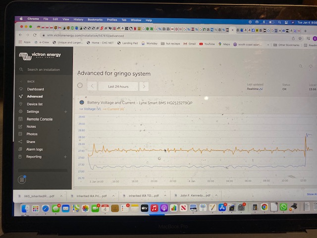
The BMS is working well, I was super impressed it balanced the batteries on the first charge. when you start charging the GX displays as it should , bulk then goes to Absorbtion at the correct voltages. What is weird is that it will go to a float voltage of 27.2 and float but not indicated float on the GX or the lights on teh multi.

img-2299.jpga9cc70a9-d747-4e4d-9876-6dc17f90d79e-1.jpgimg-2298.jpg

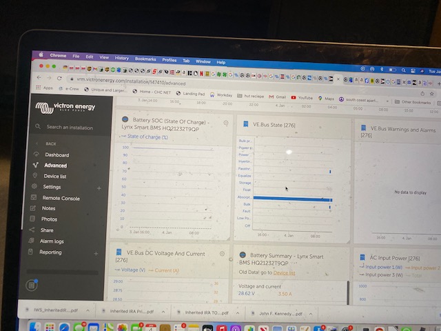
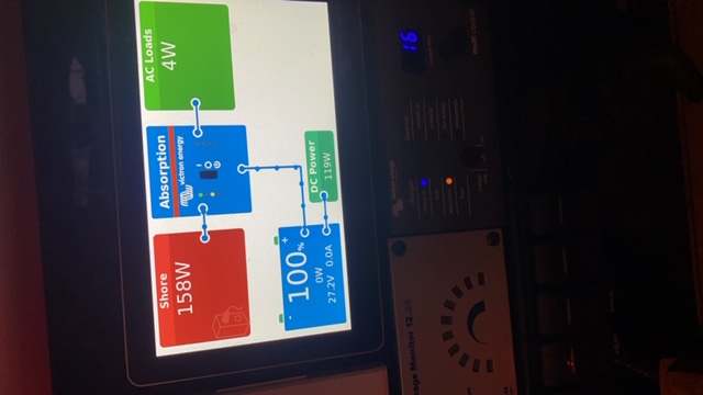
the GX is showing the status of the Mulit not what the status of whet the BMS is doing.


Have i missed something here?


Thanks


cerbo gxBMSmultiple inverters
2 |3000

Up to 8 attachments (including images) can be used with a maximum of 190.8 MiB each and 286.6 MiB total.

10 Answers
bathnm avatar image
bathnm answered ·

The reason is that the Multi is not actually running any charge algorithm, the DVCC from the Lynx BMS is controlling things. If you take a look at the DVCC section of the Cerbo/VenusOS manual it explains this.

It would be great ion the MultiPlus could display Ext.Control like the MPPTs do, and maybe at some stage that will happen.

2 |3000

Up to 8 attachments (including images) can be used with a maximum of 190.8 MiB each and 286.6 MiB total.

sv-drumbeat avatar image
sv-drumbeat answered ·

I am having the exact same issue, though with a 12v system. I understand it says so in the DVCC section of the manual, and do understand why the LEDs on the front of the Multi can't change when under remote control, but please explain why the GX Touch is not able to display 'Float' status from the Cerbo. Surely this information is - or can be made - available on the bus and is only a firmware/software issue.


After spending literally several tens of thousands of dollars on a premium Victron-only system to prevent precisely this kind of weirdness, I find this extremely disappointing, and hope this can be easily rectified, and soon. Unlike the rock-soid VE.Bus BMS we just took out which provided a simple to understand status, I am shocked to find out that the WAY more expensive Lynx/Cerbo combo we replaced it with is providing different and misleading information to the crew and now I'm not sure how to trust it as the vessel's master. It's not just the money I'm concerned with, it's safety and peace of mind both alongside on shore power, and at anchor. How do I know there's a problem if it only says absorption as the final state?

4 comments
2 |3000

Up to 8 attachments (including images) can be used with a maximum of 190.8 MiB each and 286.6 MiB total.

@Bathnm explained this quite well.

Additionally, bulk, absorption and float describe charge phases that are important for lead-acid chemistry but not for LiFePo4. It's all about voltage and current limits (CVL and CCL) that keep a lithium charged and under control, not bulk, absorption and float. And the Cerbo is displaying those limits (as well as a VRM widget).

Maybe you can explain a bit more why you think this is misleading and why you don't trust it?
What exactly are the benefits of continuing to show bulk, absorption, and float?


BTW, chargers that are not controlled by DVCC will still show the old 3-phase wording.

I personally see no reason to stick with words that are no longer relevant to the chemistry being used.

1 Like 1 ·
bathnm avatar image bathnm Stefanie (Victron Energy Staff) ♦♦ commented ·

Hi @Stefanie I fully agree and think you summarised the key issue with these words

“I personally see no reason to stick with words that are no longer relevant to the chemistry being used”

The Cerbo is using words that are no longer relevant and not being applied when the MultiPlus/Quatro is being controlled by the BMS. At least there is a change logged and to be worked that will change the label on the MultiPlus/Quatro to be Ext. Control like the MPPTs. That way at least from the VenusOS people will know what the MultiPlus/Quatro is doing and if it is externally controlled or following legacy change stages.

Maybe a Victron can even find a LED combination to display on the device itself.

But all of this is not a reason to not trust the system. As we both say, voltage is king and that is what needs to be checked.

0 Likes 0 ·
sv-drumbeat avatar image sv-drumbeat bathnm commented ·
Hi @Stefanie and @bathnm, thanks so much for your feedback and word of a logged change and firmware update. This is excellent news. I do understand everything you said and I am NOT disagreeing with you. I understand it's about CVL and CCL, and that the terminology of previous chemistries doesn't "really" apply any longer in the same way; we are all getting to the crux of the matter here though, that there is perhaps a need for some new standard nomenclature or indicators (at least within the Victron suite of products when the same battery chemistries are employed).


My thoughts about it being misleading... I will need to carefully synthesize something offline when I've had a chance to think about it fully and I'm not "distracted" by work. :-)


0 Likes 0 ·
bathnm avatar image bathnm commented ·

Victron will be addressing through a firmeware update so that at least the Cerbo will report external control for the the MultiPlus/Quattro in the sma e way the MPPTs do. The LEDs will be unlikely be changed, but with the device hidden away who actually uses them in a day to day basis.

What you need to consider is two things. (1) what phase of charge is the MultiPlus/Quattro in to maintain the charge voltage the Lynx BMS is calling for. In order to maintain the 13.5v that we all assume to be a float voltage, the internal algorithm the MultiPlus/Quattro might be in is absorption and not float, so technically the label is correct as the device has not internally swapped to a float phase, but has restricted its output as requested by the BMS (2) what the voltage is, as that is more important than a label that has been used to denote a mode.

It will all be addressed in a firmware upgrade of I suspect the MultiPlus/Quattro and the VenusOS.

if you really want to know what is going on you need to look in the Lynx BMS menu page parameters and see what the CVL is calling for.


0 Likes 0 ·
1642750601579.png (1.0 MiB)
Jmarc avatar image
Jmarc answered ·

Hi,
1) More than one answer mentioned the DVCC Manual section. It does describe how the DVCC uses the CVL and CCL but I do not seem to find what section explain the Charging States implication.screenshot-2024-02-15-133742.png
2) Yes the Overview now does show "Ext-Control" which is good. But in the Device status and on VRM, the unit is either in Bulk or Absorption as I can see for a Lithium battery system. It never switch to float.
Is this important: Not in my mind since effectively for Lithium Battery there are no distinction of absorption and float. It is either Current controlled or Voltage Control which both Bulk and Absortion respectively are. But for many people used to the Lead acid type, they look for the Float to tell them it is done charging... Which never happens... Disconcerting at first


2 |3000

Up to 8 attachments (including images) can be used with a maximum of 190.8 MiB each and 286.6 MiB total.

thebelcherman avatar image
thebelcherman answered ·

I thought I had read that passage that @Jmarc quoted, but for the life of me I could not find it again. Thanks man!

Enabled DVCC with my JK PB series BMS and noticed that my VE.Can MPPT's would no longer give me a green Float LED. I had read that passage and thought it just meant that for whatever reason it wasn't going to give me my green LED. But I was wrong, it flat out ignores my BMS's (RFV) Requested Float Voltage and holds my pack to the CVL.

I hear you guys talking about LiFePo4's chemistry not needing a Float voltage. New to this game, so don't come down to hard on me :) From all my reading, there is no need to keep the cells at CVL and you can lower it to say 3.375 like the MPPT's internal factory battery preset charging algorithm "Smart Lithium (LiFePo4).

So what am I missing? Victron must agree with me, since it's in their charging algorithm, no?

Question, DVCC = No Float Voltage, period?


2 |3000

Up to 8 attachments (including images) can be used with a maximum of 190.8 MiB each and 286.6 MiB total.

Jmarc avatar image
Jmarc answered ·

@TheBelcherMan beware that what I wrote assumes that the BMS is a "Smart BMS" with NMEA2000 or VeBMS canbus connection. I am not familiar with the JK PB BMS so I cannot comment on how it works and whether the use of the DVCC is recommended for your application.

DVCC needs to receive a Target Charge Voltage(CVL) and Maximum Charge current(CCL) from the BMS to work properly.

So the answer to your question "DVCC = No Float Voltage period" is NO. Meaning, the charger will go to what ever voltage target is being sent by the BMS via the network. and yes therefore it ignores any Float period and the like. It is a Slave to the Control source. Thus the display of "External Control". In fact DVCC can be used for any type of Chemistry, provided you have an intelligent source. That source may or may not have the Different Stages BULK, ABSORPTION, FLOAT. The Charger and the GX device does not specifically know what state the controlling source is.

I just did a brief internet search on the JK/PB bms and I did not see one that has canbus interface. So I am not sure DVCC is appropriate for the application.
As far as the MPPT that you mentioned, When controlled by DVCC, my experience is that LED stay in Bulk as long as the unit is producing power. As soon as their current is below a threshold they switch to Float.
A properly designed smart lithium charger will choose a voltage target as a function of the highest cell voltage not as the pack voltage to avoid overcharging any single cell. In the case of LIPO battery where the charge voltage curve is extremely sharp in the last 3 % of a charge this is a critical function.
The recommended charge profile for a Cell is a CC/CV profile meaning it charges based on Maximum current until a single cell reach the cell target voltage. At that point the charger will decrease the current to maintain the constant voltage of that cell as specified by te manufacturer. When the Current is below threshold, the charge is considered to be complete. There are no Bulk, Absorption or Float voltage to speak of.

2 |3000

Up to 8 attachments (including images) can be used with a maximum of 190.8 MiB each and 286.6 MiB total.

thebelcherman avatar image
thebelcherman answered ·

@Jmarc

This is deep, but I'm digging it. While I'm reading, the model is "JK-PB2A16S20P" and a screenshot of it's controls.

It does work, sort of. I'll explain further after I digest your comment.


JK-BMS-Monitor.png


jk-bms-monitor.png (168.7 KiB)
2 |3000

Up to 8 attachments (including images) can be used with a maximum of 190.8 MiB each and 286.6 MiB total.

thebelcherman avatar image
thebelcherman answered ·

This is the BMS, don't think I've see this video. But I'm watching now.

https://youtu.be/F6OnHQ0TEbg?t=395

2 |3000

Up to 8 attachments (including images) can be used with a maximum of 190.8 MiB each and 286.6 MiB total.

thebelcherman avatar image
thebelcherman answered ·

He's got it working, I must have something misconfigured.

2 |3000

Up to 8 attachments (including images) can be used with a maximum of 190.8 MiB each and 286.6 MiB total.

thebelcherman avatar image
thebelcherman answered ·

@Jmarc


Never been the Parameters page for my BMS. It shows, the CVL, CCL and DCL live values.

Thanks mate, your explanation pointed me in the right direction. I'll get this thing working!


2 |3000

Up to 8 attachments (including images) can be used with a maximum of 190.8 MiB each and 286.6 MiB total.

thebelcherman avatar image
thebelcherman answered ·

@Jmarc

Got it working, thanks again for your help!

2 |3000

Up to 8 attachments (including images) can be used with a maximum of 190.8 MiB each and 286.6 MiB total.

Related Resources