question

johndevon avatar image
johndevon asked

Where to connect smart shunt

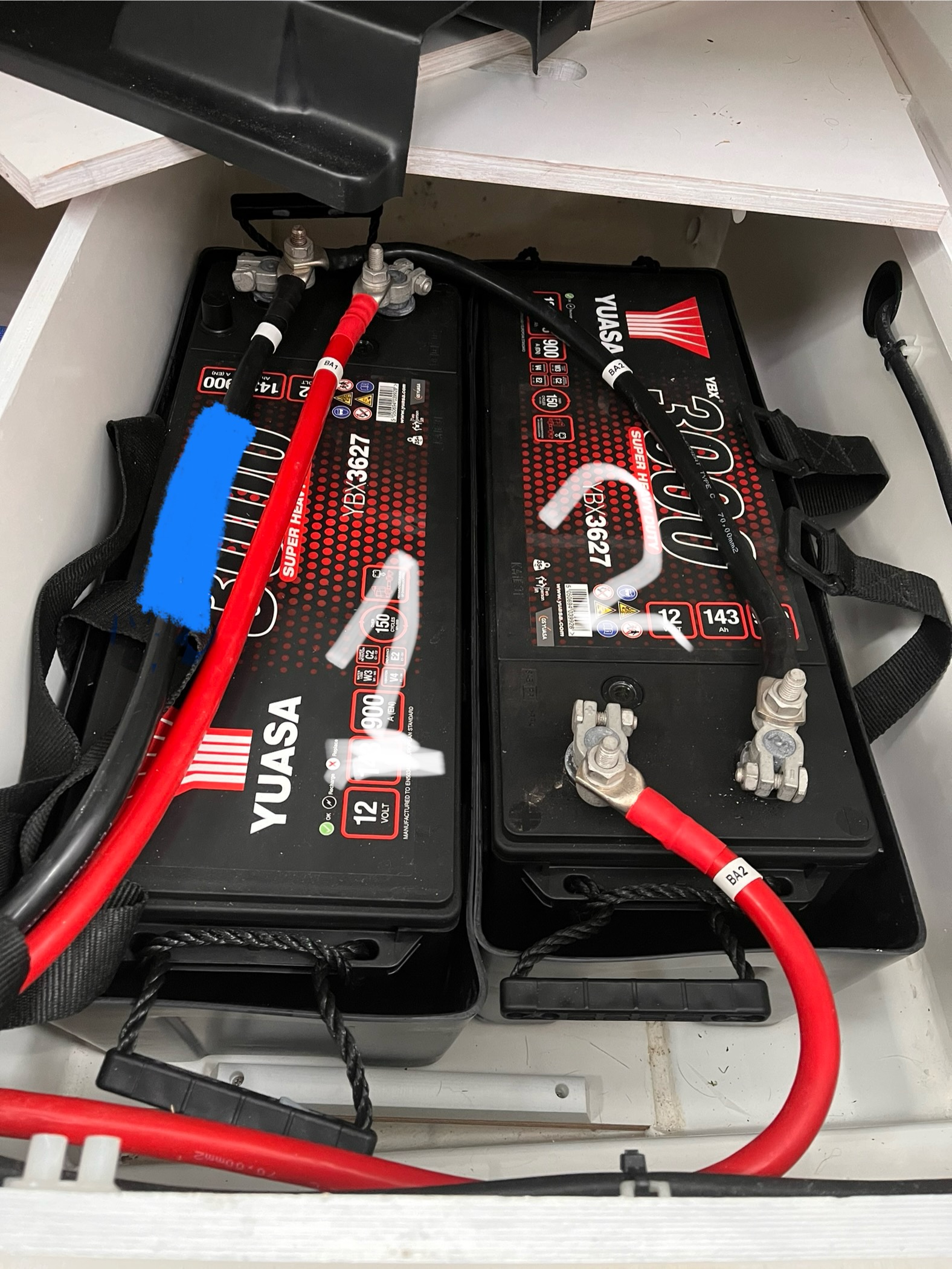
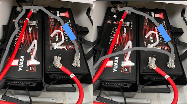
Apologies for the very basic question. Is it correct to add the smart shunt at the position shaded blue? Taking the current negative wire and putting it on the load side of the shunt and then connecting a new wire between the other side of the shunt and the negative terminal on batt 1? I then add the small positive/red wires from the shunt to each battery?


Many thanks in advance for any guidance .

img-4827.jpeg

SmartShunt
img-4827.jpeg (682.8 KiB)
2 |3000

Up to 8 attachments (including images) can be used with a maximum of 190.8 MiB each and 286.6 MiB total.

6 Answers
pwfarnell avatar image
pwfarnell answered ·

Correct, the shunt will go at the blue location as you have described. I can not see any other connections to the negative terminals on either battery so this is be good, but if there are any move then to the load side of the shunt.

The main red wire goes to battery 1 positive.

Is battery 2 on a different circuit, if so then the aux connection goes to battery 2 positive. If battery 2 is wired in parallel with battery 1 then you do not need to connect the aux terminal.

2 comments
2 |3000

Up to 8 attachments (including images) can be used with a maximum of 190.8 MiB each and 286.6 MiB total.

cybermaus avatar image cybermaus commented ·
Are you sure? I do not want to confuse the matter, but I think if "is battery 2 on a different circuit" then the blue location is incorrect. As it would count *both* battery amp-hours, without knowing where to assign it. Please @Johndevon enlighten us how the red cable run.
0 Likes 0 ·
pwfarnell avatar image pwfarnell cybermaus commented ·
Yes, worth checking, thanks.
0 Likes 0 ·
johndevon avatar image
johndevon answered ·

Thanks for the replies. The batteries are on a boat that is new to me. I've tried to trace the positive cables but they disappear through some bulk heads but what I can see is they do eventually come through to a batter charger which has multiple red wires running into it. There is also 2 solar panels which has outputs for 2 batteries with cables running from it. There are also isolator switches for 2 batteries, so I think this means they are on separate circuits?

In that case it sounds like my blue shaded area is in the wrong place? If so where would you think it should go.

Many thanks.
John

2 |3000

Up to 8 attachments (including images) can be used with a maximum of 190.8 MiB each and 286.6 MiB total.

cybermaus avatar image
cybermaus answered ·

If the red wires join, the shunt is in the correct position, but to be honest, it is weird that the red wires do not join directly at the battery, like the black one does. So I would assume they are indeed separate circuits. But assuming is dangerous.

Best measure it: Disconnect both red cables one at a time, and measure with a multimeter where they are connected, and if they are both connected to each other. And while you are at it, may as well draw out a full diagram.


If they are not connected then with one shunt you can only measure SoC of one battery. Which one? Whichever you want to measure, that should be on the SmartShunt separately.


If they are separate, usually one is for starting/running the engine only, and the other for living (lights, cooking, laptop, and other frivolous use) Usually the living battery is the one you want to measure, as that is the one at risk of draining over long time.


If they are both for living, consider joining them properly. But for that, you may need to supply the full schematic.


1 comment
2 |3000

Up to 8 attachments (including images) can be used with a maximum of 190.8 MiB each and 286.6 MiB total.

klim8skeptic avatar image klim8skeptic ♦ commented ·

@Johndevon it is weird that the red wires do not join directly at the battery, like the black one does.

I concur with this. It looks like both batteries wont equally share the charge/load current. A short life for 1 of the batteries.

0 Likes 0 ·
johndevon avatar image
johndevon answered ·

Thank you. I will do some more research, but I am starting to think that there is one for starting and one for everything else. There is a switch that allows the batteries to be linked for starting so that makes me think that they are in separate circuits.

1 comment
2 |3000

Up to 8 attachments (including images) can be used with a maximum of 190.8 MiB each and 286.6 MiB total.

klim8skeptic avatar image klim8skeptic ♦ commented ·

@Johndevon There is a switch that allows the batteries to be linked for starting so that makes me think that they are in separate circuits.

If your batteries have different loads and charging sources, that will affect where the shunt has to be placed.

It would be best to work out where each battery positive lead go to and report on loads and chargers are connected.

0 Likes 0 ·
cybermaus avatar image
cybermaus answered ·

Assuming separate circuits, left picture if you want to monitor SoC on battery `2.
right picture if you want to monitor SoC on battery 1

capture.jpg

But overall, you should still make a proper schematic for yourself


capture.jpg (109.1 KiB)
2 |3000

Up to 8 attachments (including images) can be used with a maximum of 190.8 MiB each and 286.6 MiB total.

johndevon avatar image
johndevon answered ·

Thank you all. This help is very useful. I will get to work working out schematic to get to the bottom of what I have.

2 |3000

Up to 8 attachments (including images) can be used with a maximum of 190.8 MiB each and 286.6 MiB total.