question

amidships avatar image
amidships asked

EasyPlus Compact 12/1600/70 sudden restart during end of battery charging during Absorption

I am running firmware v485, and my EasyPlus is attached to a 200Ah LiFeP04 battery with on board BMS.

I am testing the system in lab before final installation and I noticed this behaviour.

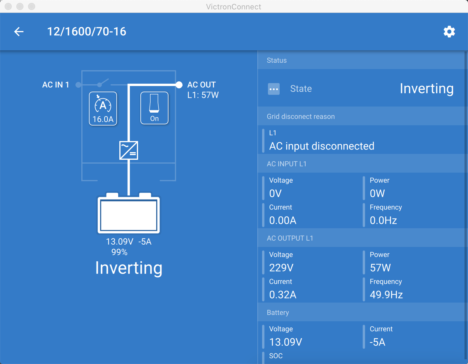
I lightly discharge the battery using the inverter, let's say to 13.09V

2021-08-16-18-13-17-3.png

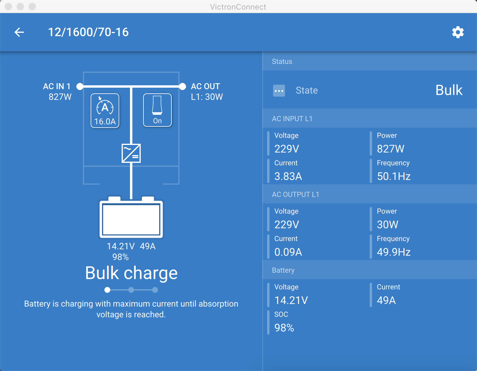
The I attach the mains and the charging starts. First the bulk phase kicks in at 50A

1629130944286.png

Then it soon enter the absorption phase and current decreases:

1629130987444.png

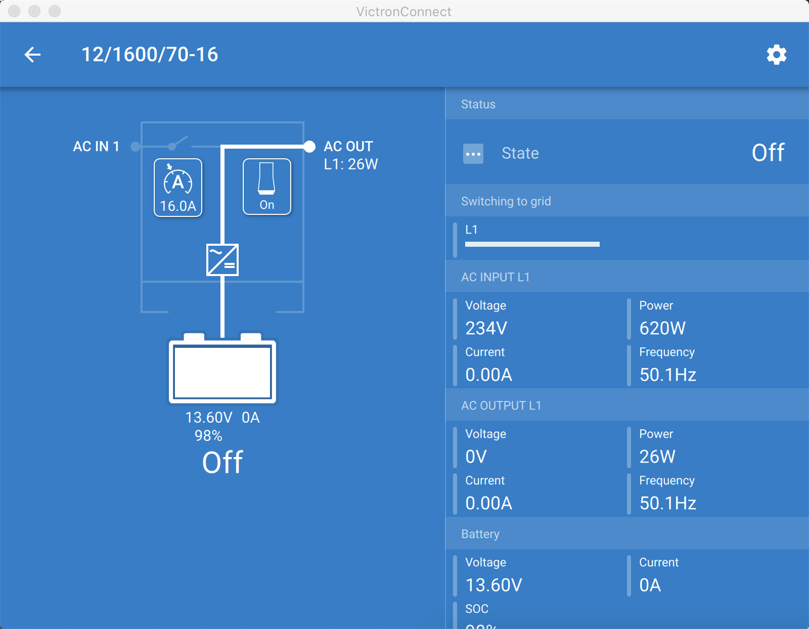
Suddenly the Inverter and Charger switches off without any warning or errors. It comes back online after few seconds.

1629131046236.png

It then enter again insto absorption phase where it stays permanently at 98% drawing 0A

1629131118700.png

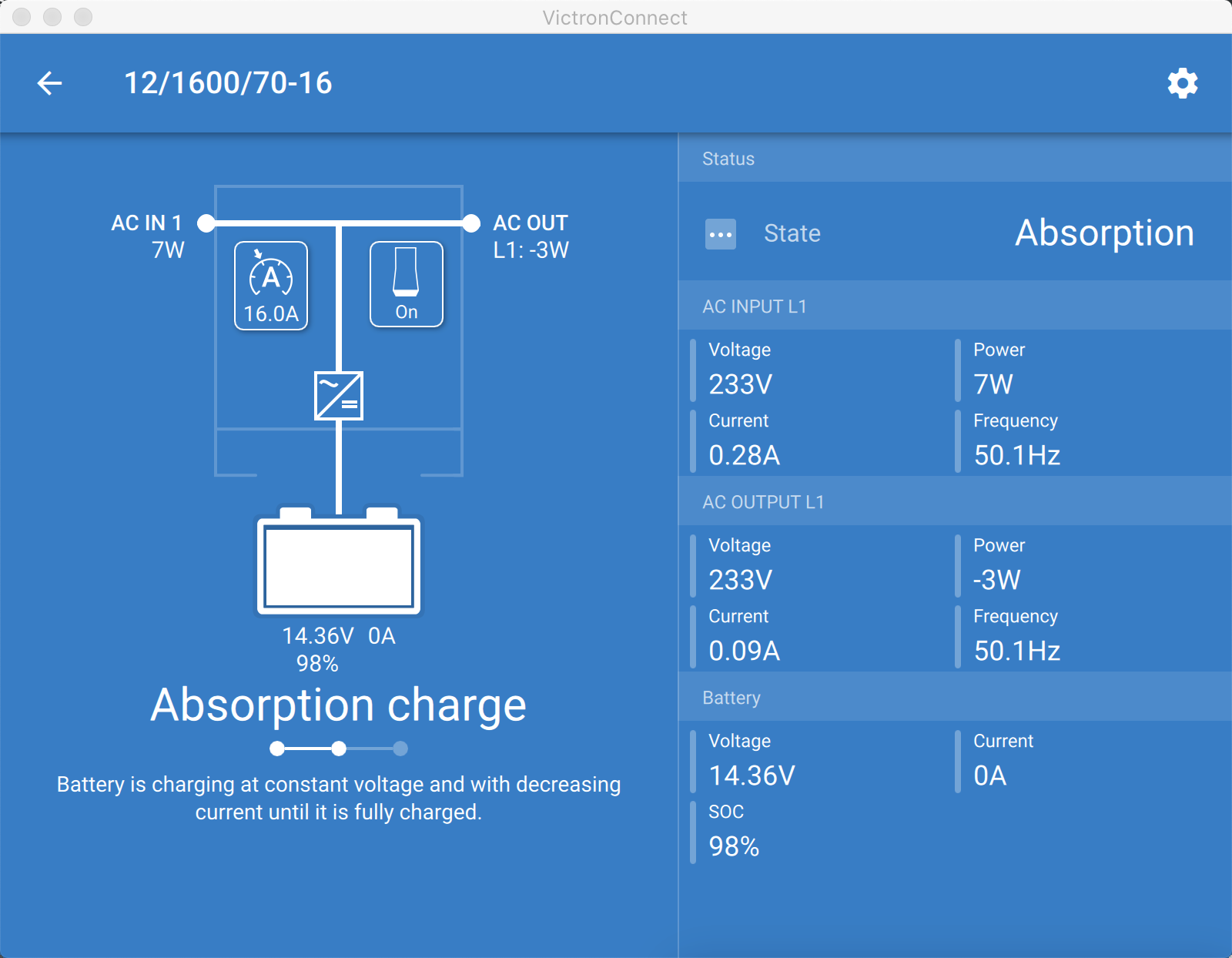
I have tried the above with and without AC loads connected but it's alway the same. The EasyPlus kind of "restart" during the current ramp down of the absorption charge and reconnect staying in absorption at 0A and 98% forever.

Any idea?


Thanks!


battery chargingchargerEasyPlus
1629130944286.png (210.6 KiB)
1629130987444.png (225.1 KiB)
1629131046236.png (185.7 KiB)
1629131118700.png (220.8 KiB)
2 |3000

Up to 8 attachments (including images) can be used with a maximum of 190.8 MiB each and 286.6 MiB total.

1 Answer
Matthias Lange - DE avatar image
Matthias Lange - DE answered ·

This can happen if the BMS suddenly cut off the current flow into the battery.

Try to lower the charging current and let the BMS slowly balance the cells.

This should only be necessary at the very first charging.

2 comments
2 |3000

Up to 8 attachments (including images) can be used with a maximum of 190.8 MiB each and 286.6 MiB total.

amidships avatar image amidships commented ·

Thank you very much for the hint. I will try to redo the whole test using 25A as the charging current instead of 50A. But I will still keep 14,4V as absorption voltage as for battery specification (instead of the default 14,2V)

Would you spot any mismatch based om the spec I list here or have good suggestions for a proper charger setup, you are more then welcome to comment.

Thanks!

Specification of battery pack


Electrical Characteristics

Nominal Voltage

12.8V

Nominal Capacity

Minimum: 200Ah

Energy

2560Wh

Internal Resistance

≤30mΩ

Cycle Life

>2000 cycles @1C 100%DOD; >3000 cycles @1C 80%DOD;

Months Self Discharge

<3%

Efficiency of Charge

100% @0.5C

Efficiency of Discharge

96~99% @1C

Standard Charge

Charge Voltage

14.4±0.2V

Charge Mode

CC/CV

Recomm.Charge Current

50A

Max. Charge Current

100A

Charge Cut-off Voltage

14.6V

Standard Discharge

Continuous Current

150A

Max. Pulse Current

500A

Discharge Cut-off Voltage

10V

Environmental

Charge Temperature

0 ℃ to 45 ℃ (32F to 113F) @60±25% Relative Humidity

Discharge Temperature

-20 ℃ to 60 ℃ (-4F to 140F) @60±25% Relative Humidity

Storage Temperature

0 ℃ to 40 ℃ (32F to 104F) @60±25% Relative Humidity

Plastic Case

ABS+PC UL V-0 flame resistant

Dimensions (in./mm.)

L520*W232*H217mm

Weight (lbs./kg.)

27kg

Terminal

M8

Protocol (optional)

Bluetooth


Specification of BMS board


Voltage

Charging voltage

DC:14.4V 3.6V/Cell (CC/CV)

Balance voltage for single cell

3.60±0.05V

Current

Balance current for single cell

116±10mA

Current consumption

≤600μA

Maximal continuous charging current

150A

Maximal continuous Discharging current

150A

Over charge Protection

Over charge detection voltage

3.75±0.05V

Over charge detection delay time

0.5S—2S

Over charge release voltage

3.6±0.1V

Over discharge protection

Over discharge detection voltage

2.2±0.1V

Over discharge detection delay time

10mS—400mS

Over discharge release voltage

2.7±0.1V

Over current protection

Over current detection current

500±50A

Detection delay time

5ms—60ms

Release condition

Cut load,charge release

Short protection

Detection condition

Exterior short circuit

Detection delay time

200-800us

Release condition

Cut load,charge release

Resistance

Protection circuitry

≤50mΩ

Temperature

Operating Temperature Range

-40~+85℃

Storage Temperature Range

-40~+125℃


0 Likes 0 ·
amidships avatar image amidships commented ·
@Matthias Lange - DE , I tried your suggestion of lowering the charging current but the problem still occurs.

Assuming that you are right about the BMS cutting off the current, why should the EasyPlus go in Off and then restart without a warning/alarm? I don't seem to ready about this behaviour in the manual

0 Likes 0 ·

Related Resources

Additional resources still need to be added for this topic