Hello! We are building a 25' all-electric boat, with various Victron components and hoped to get some advice from the community. Questions are up top with details of the system farther down.
Questions:
Battery Protection: We need to have battery under/over voltage protection on the 48V bank, but the largest 48V battery protect from Victron is 100A, which isn't high enough to have just one (We anticipate a potential burst load of say 8kW for 30 seconds or so, which is a 166A load). We could monitor each individual 48V battery with a separate BatteryProtect, but is this the best way to monitor and protect the batteries?
General System Design: Does anyone see a problem with what we have proposed in the diagram below? Any gotchas to watch out for? We are hoping the Cerbo GX and GX Touch 50 + iphone apps will provide monitoring and alarms for system operation.
12V system and battery: We need a 12V battery and require monitoring and protection for it, ideally victron branded and something we can monitor using with the GerboGX alongside the rest of the system. It doesn't appear that the 12V batteries from Victron natively connect to the Cerbo GX, will this require a BMV712 or smartshunt to be monitored? And if so, which is recommended?
Solar System: We will probably have two different sizes of solar panels on the roof of the boat, potentially with different nominal voltages, would that require two different solar charge controllers? Thoughts on flexible vs rigid panels, and the Victron charge controllers that would be best? We haven't purchased the panels yet so needed details are missing but any general advice is appreciated.
Diagram: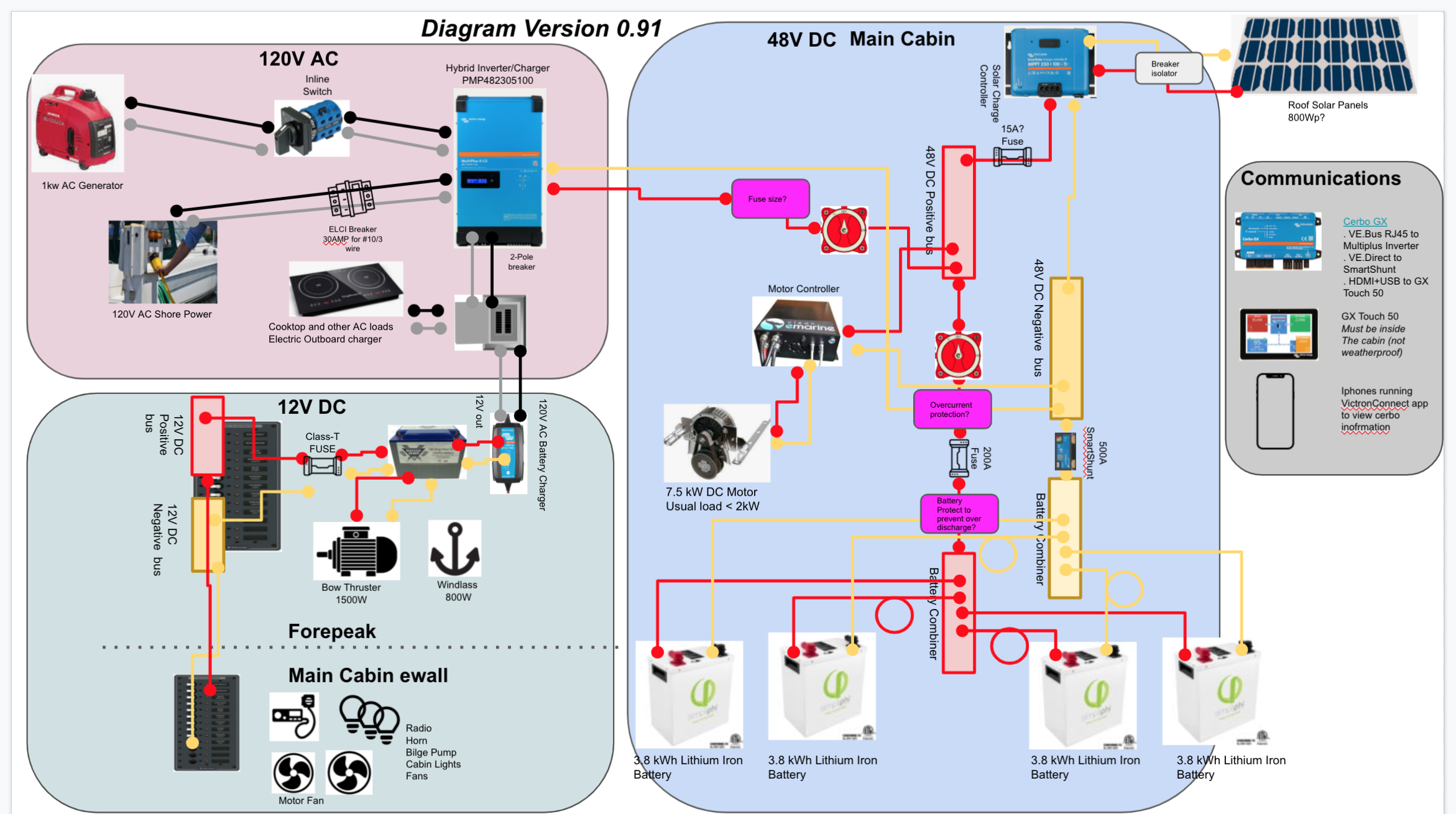
Background:
Gavia Electrical System Design

Description: Gavia is a 25’ all-electric solar motor boat under development.
48V DC System: The motor is a brushed 7.5 kW DC 48V Thoosa Electric Motor. We hope the nominal draw will be around 1-2 kW while under way, but short bursts (1 minute) of 7.5kW are expected (we have not tested the boat in the water yet). Energy will be provided by a 48V lithium-iron battery bank. Solar cells on the roof will be the primary recharge method, hopefully 1kWp or greater, with AC shore power and backup 1kW generator for AC charging on-the-go. A hybrid inverter/charger should be a convenient way to pack lots of functionality into one box, and AC input/output should be 120V (we are in the USA).
12V DC System: The 12V DC system will be used to run low-wattage house electronics (navigation, radio, windless, house lighting, etc), and 12V bow thruster whose max draw is 1500W. This larger 12V draw necessitates a 12V energy bank (vs relying on DC-DC converter), so a 12V 100+A lithium battery will be used and it should recharge from the main 48V system.
120V AC: 120V AC will be used for a minimum number of appliances onboard, the largest of which is the induction cooktop with a 1800W maximum draw. This will be provided by the hybrid inverter/charger.
Note that we do not anticipate running the high power loads at the same time. For example, we won’t run the induction cooktop while the electric motor is running.
Here are some system components:
- Inverter/Charger: "PMP482305100 MultiPlus-II 48/3000/35-50 120V"
- 48V Bank: SimpliFi PHI 3.8-M ("PHI3.8 48V 60 VTE BRK") wired in parallel (x4)
- Onboard component monitoring (interior): "Victron Energy BPP900455050 GX Touch 50" with "Victron Energy BPP900450100 Cerbo GX". Onboard component monitoring (exterior helm station): ipad similar device running victron app, with weatherproof case
- Battery Capacity Shunt: "Victron Energy SHU050150050 SmartShunt 500A/50mV"
- Battery Protect: Undervoltage/overvoltage protection: The batteries have a BMS, but we need an additional protection for the battery bank as a whole or the individual batteries.
- 12V DC Charger: We will use an AC battery charger to charge the 12V bank. We cannot use a DC-DC charger for this because the Victron DC charger is not isolated; the motor requires no other DC systems on the negative side of the 48V system
- 12V House Loads Battery: something with 1kWh of energy and built-in BMS, and some way to monitor the voltage.