question

warren-b avatar image
warren-b asked

Lynx Shunt VE.Can Installation and Wiring

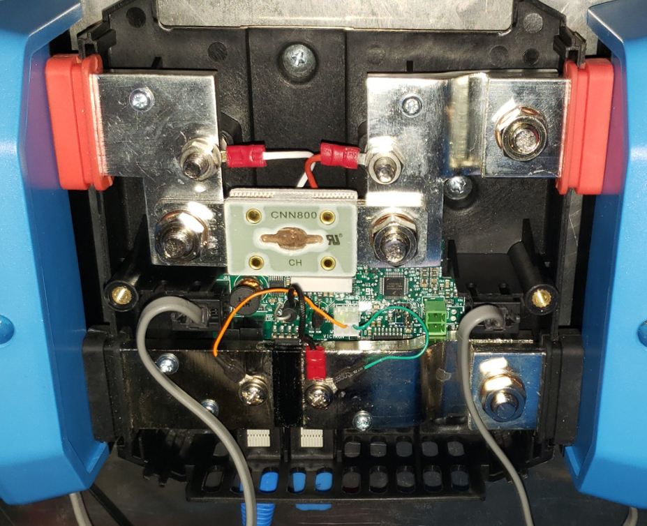
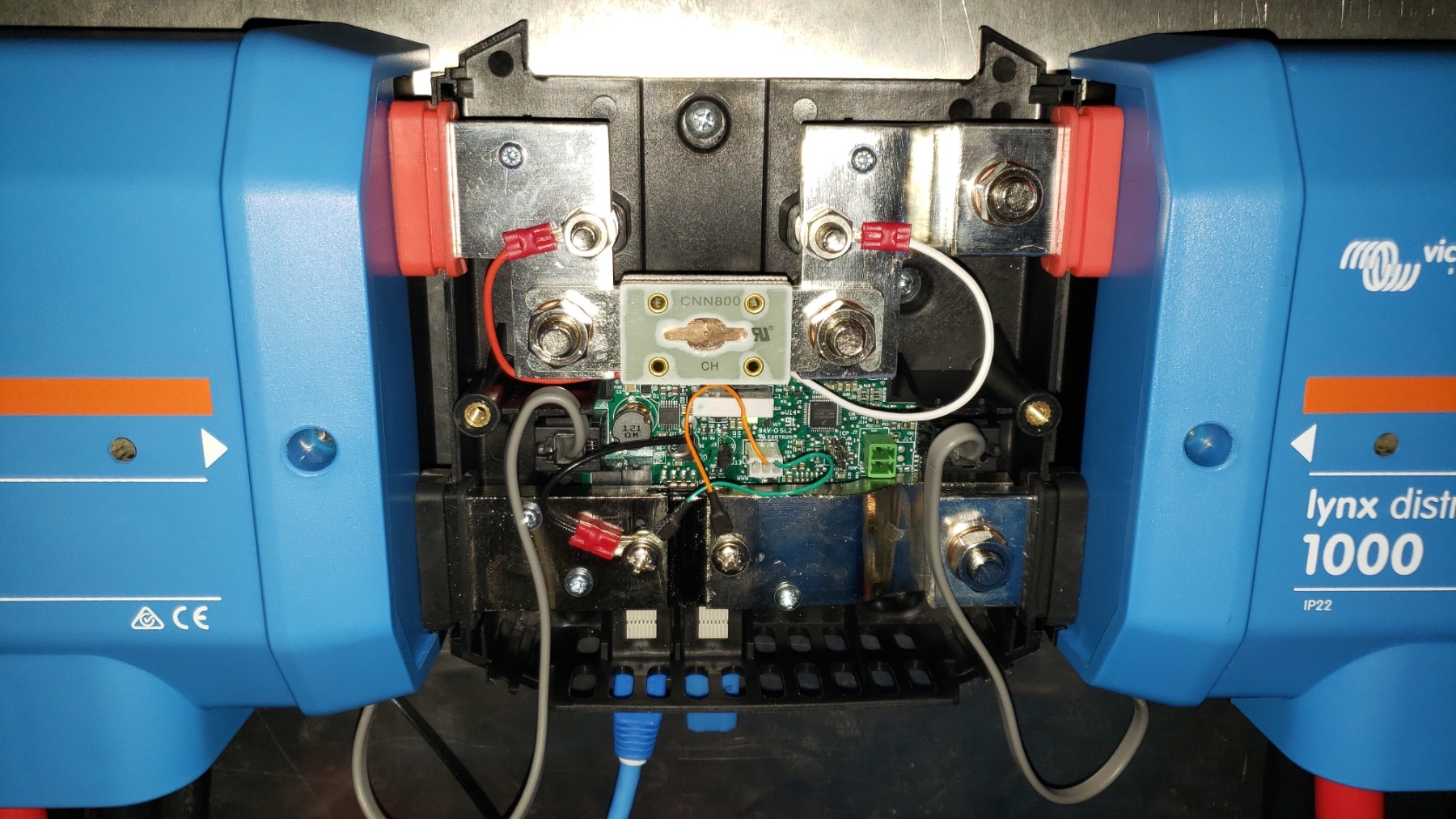
I am aware that a new Lynx Shunt VE.Can is initially set up to have the battery distribution to its left and the load distribution to its right. Is it possible to modify the Lynx Shunt to allow for the battery distribution to be on the right instead?

I am wondering if changing the position of all or some of the five sensing wires inside the unit would allow for changing the location of the battery distribution. If it is possible, which wires need to be moved and to which positions? If this is not possible by physically moving sensor connections, is there a software setting that could be changed?

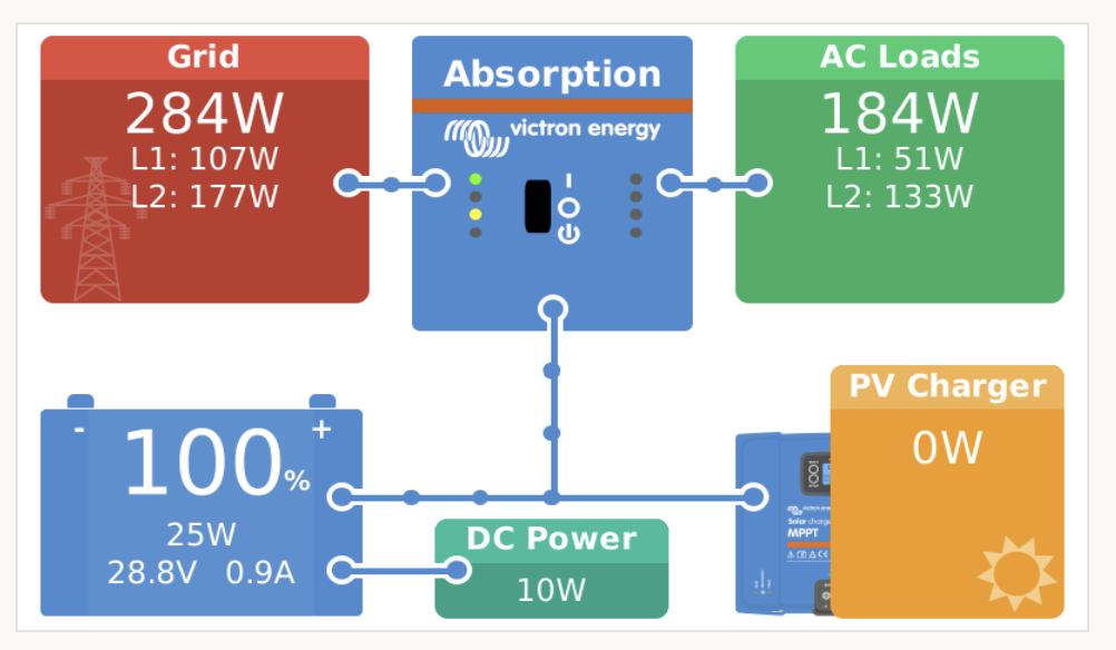
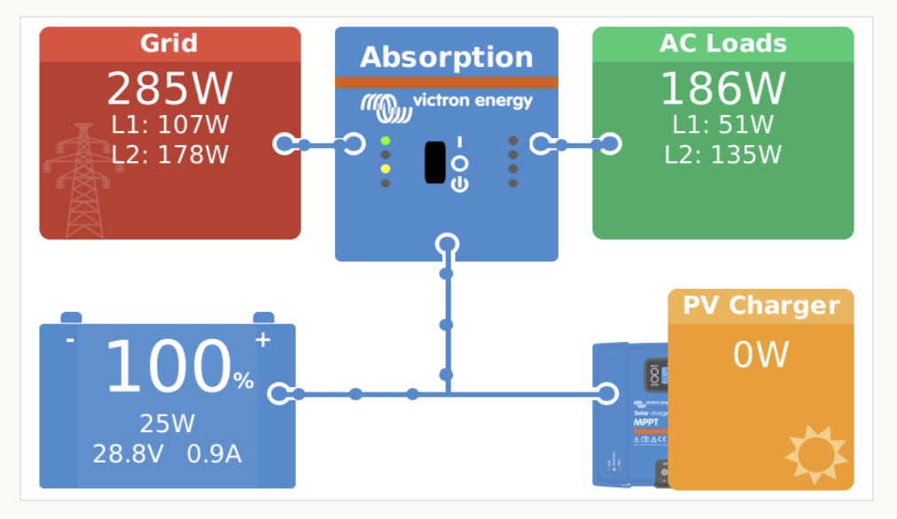
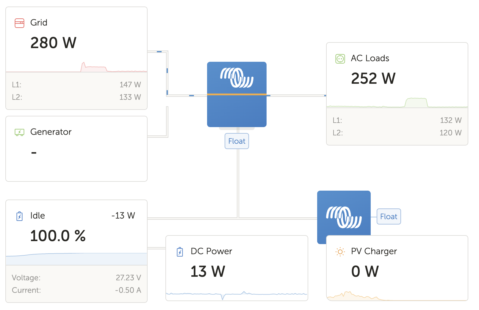
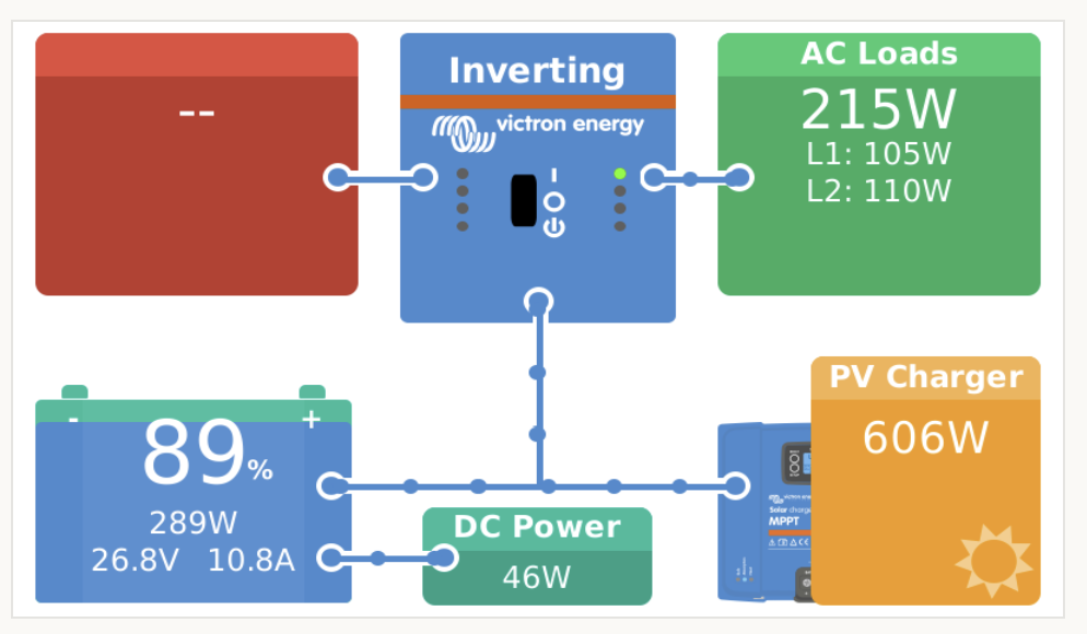
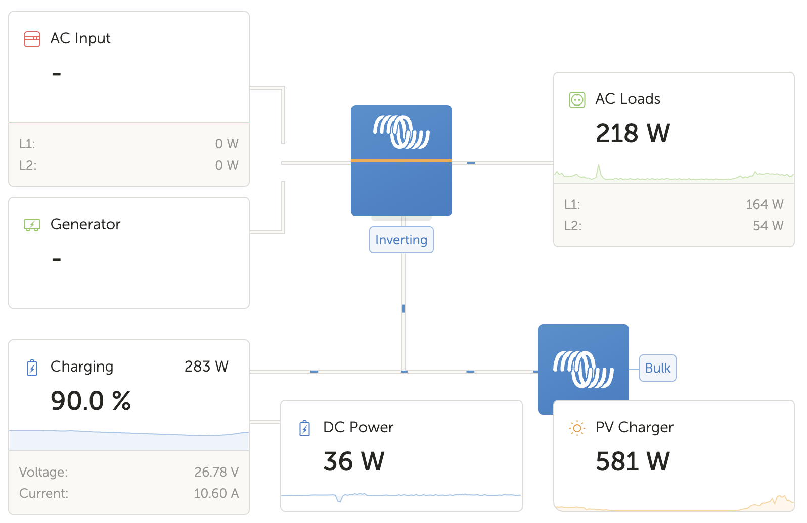
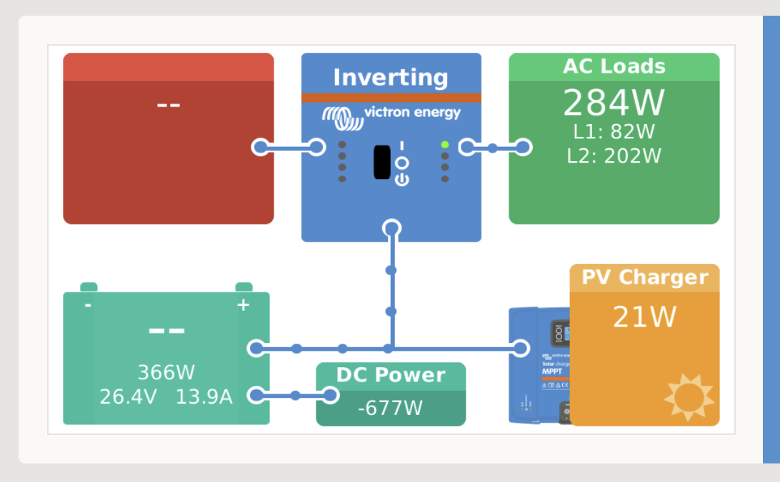
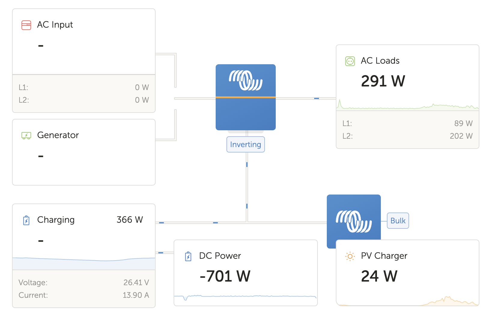
My system is currently set up with the battery distribution on the right side of the Lynx Shunt. Based on my VRM portal reports the shunt is measuring the current flow in the opposite direction for how the system is connected. As an example, if my battery bank (9.6kW capacity) SOC drops from approximately 100% to 21% and my inputs are 1kWh from the grid and 21 kWh from the PV array, the VRM is reporting my consumption as 15kWh. Based on those input numbers (which I assume are collected directly from the Multiplus and MPPT), I think that the consumption number should be around 29kWh.

My system is:

8 x Battleborn 12V LiPO batteries (configured as a 24V 400Ah bank)

2 x Multiplus 24/3000/70

1 x SmartSolar MPPT 150/85

1 x Orion 24/12-70

2 x Lynx Distributor (used on battery and load sides)

1 x Lynx Shunt VE.Can

1 x Cerbo GX

1 x GX Touch 50

@Matthias Lange - DE @mvader (Victron Energy) @Daniël Boekel (Victron Energy Staff) - user overview - Victron Community

BMV Battery MonitorSmartShuntVE.Canlynx shunt
2 |3000

Up to 8 attachments (including images) can be used with a maximum of 190.8 MiB each and 286.6 MiB total.

1 Answer
seb71 avatar image
seb71 answered ·

See here (natebert's post).

11 comments
2 |3000

Up to 8 attachments (including images) can be used with a maximum of 190.8 MiB each and 286.6 MiB total.

warren-b avatar image warren-b commented ·

Thanks for the quick reply, @seb71 ! I have temporarily tried that wiring arrangement briefly once before. I didn't leave it in that arrangement long enough to get a usable amount of VRM data to see if it fixed the large Consumption discrepancy because using the GX Touch 50 I could see right away that the DC Power was getting reported backwards (i.e. turning on a light would be represented in negative watts in the DC Power consumption on the GX Touch 50). I have since learned that the DC Power value is a calculated number, not a measured one. Is there a way to change how that number is calculated?

0 Likes 0 ·
seb71 avatar image seb71 warren-b commented ·

By "DC power" you mean power drawn from battery or the "DC system" power from Cerbo GX?

0 Likes 0 ·
warren-b avatar image warren-b seb71 commented ·

I mean the "DC Power" reported on the GX and VRM like this:

screen-shot-2021-03-19-at-12529-pm.png

screen-shot-2021-03-19-at-12719-pm.png

The DC power is used by the Orion 24/12-70 and a small amount of other 24V electronics.

0 Likes 0 ·
seb71 avatar image seb71 warren-b commented ·

So how was the Lynx Shunt wired when you took those screenshots?


And which value has the sign reversed compared with reality?

0 Likes 0 ·
warren-b avatar image warren-b seb71 commented ·

Currently, the shunt is wired the standard way, and when a 12VDC light is turned on the "DC Power" number increases positively. Here is a picture

viber-image-2021-03-19-15-57-55.jpg


0 Likes 0 ·
warren-b avatar image warren-b seb71 commented ·

Just to test your suggestion and to see if the my previous results were repeatable, I reversed the sensor wires as shown below.

viber-image-2021-03-19-18-05-24-copy.jpg

And as you can see below from the GX an VRM, the DC Power reading becomes negative. There is not anything that would be charging the batteries from the DC Power connections, especially at over 600W.

screen-shot-2021-03-19-at-54540-pm.png

screen-shot-2021-03-19-at-54632-pm.png

Maybe, @Guy Stewart (Victron Community Manager), has some input since he was involved in the thread you mentioned.

0 Likes 0 ·
seb71 avatar image seb71 warren-b commented ·

How does it look if you disable "Has DC system" in Cerbo GX?


And what you have there set for Battery monitor?

0 Likes 0 ·
warren-b avatar image warren-b seb71 commented ·

The Battery Monitor is set to Automatic, and the auto select has chosen the "Lynx Shunt 1000A VE.Can on VE.Can." I am not sure what difference disabling "has DC System" has on the rest of the system, but here are screenshots with and without it.

screen-shot-2021-03-20-at-122116-am.pngscreen-shot-2021-03-20-at-122146-am.png

0 Likes 0 ·
seb71 avatar image seb71 warren-b commented ·

According with the last two screenshots, the battery is charged from the grid. Is that actually the case?

In the first screenshot the DC Power this time is positive, so probably correct.


The purpose of disabling "Has DC system" is to first check if current in/out of the battery is shown correctly in this simplified (basic) case.


Is everything (except the batteries) connected/wired after the shunt? Loads and chargers.

0 Likes 0 ·
warren-b avatar image warren-b seb71 commented ·

It was being charged from the grid at that time. This is an RV installation, with 50A split phase grid service and a 1920W PV array. The DC Power is positive in the last screen shots because I switched the sensor wiring back to the original (out of the box) positions.

Everything is wired correctly regarding what is before and after the shunt. This was the status of the system this morning.screen-shot-2021-03-20-at-95836-am.png

I am planning on doing a "Calibrate Zero Current" and "Synchronise State of Charge to 100%" today to see if things get better over the weekend.

0 Likes 0 ·
Sarah avatar image Sarah warren-b commented ·

Hi - I’m not sure if it helps but I had to recently ‘flip’ my Lynx Shunt and swapped all five wires (4 four screws) without incident (it was originally installed upside down to accomodate the battery feed on the right) . Cerbo GX continues to read correctly. Sarah.

0 Likes 0 ·

Related Resources

Victron BMV battery monitors product page

Additional resources still need to be added for this topic