question

peterb381 avatar image
peterb381 asked

Victron 100/50 + Inverter Wiring Setup Help?

Hey guys, this is the very simple setup I intend to run in the coming weeks - can you please help me with the following:

screenshot-2021-03-14-213823.jpg
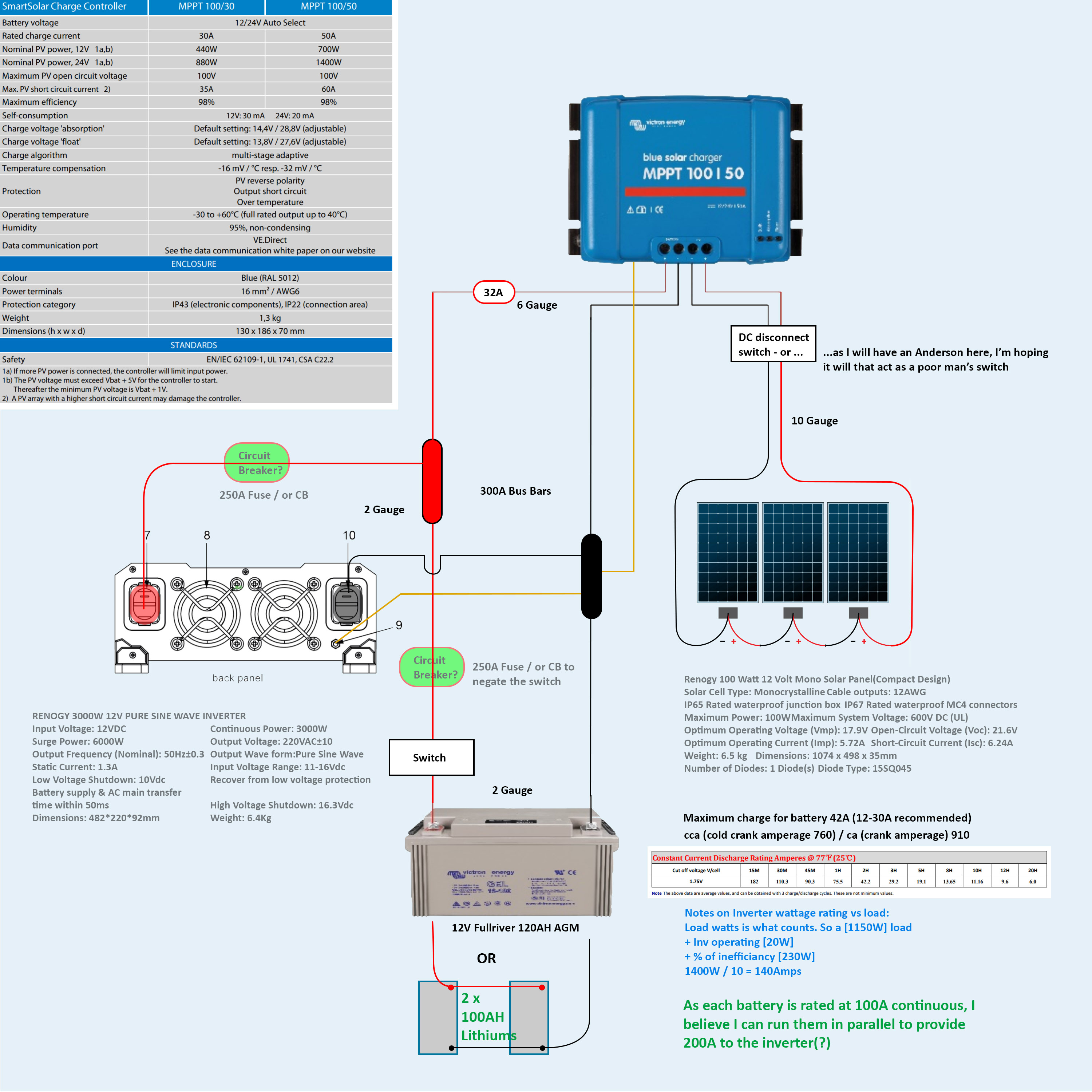
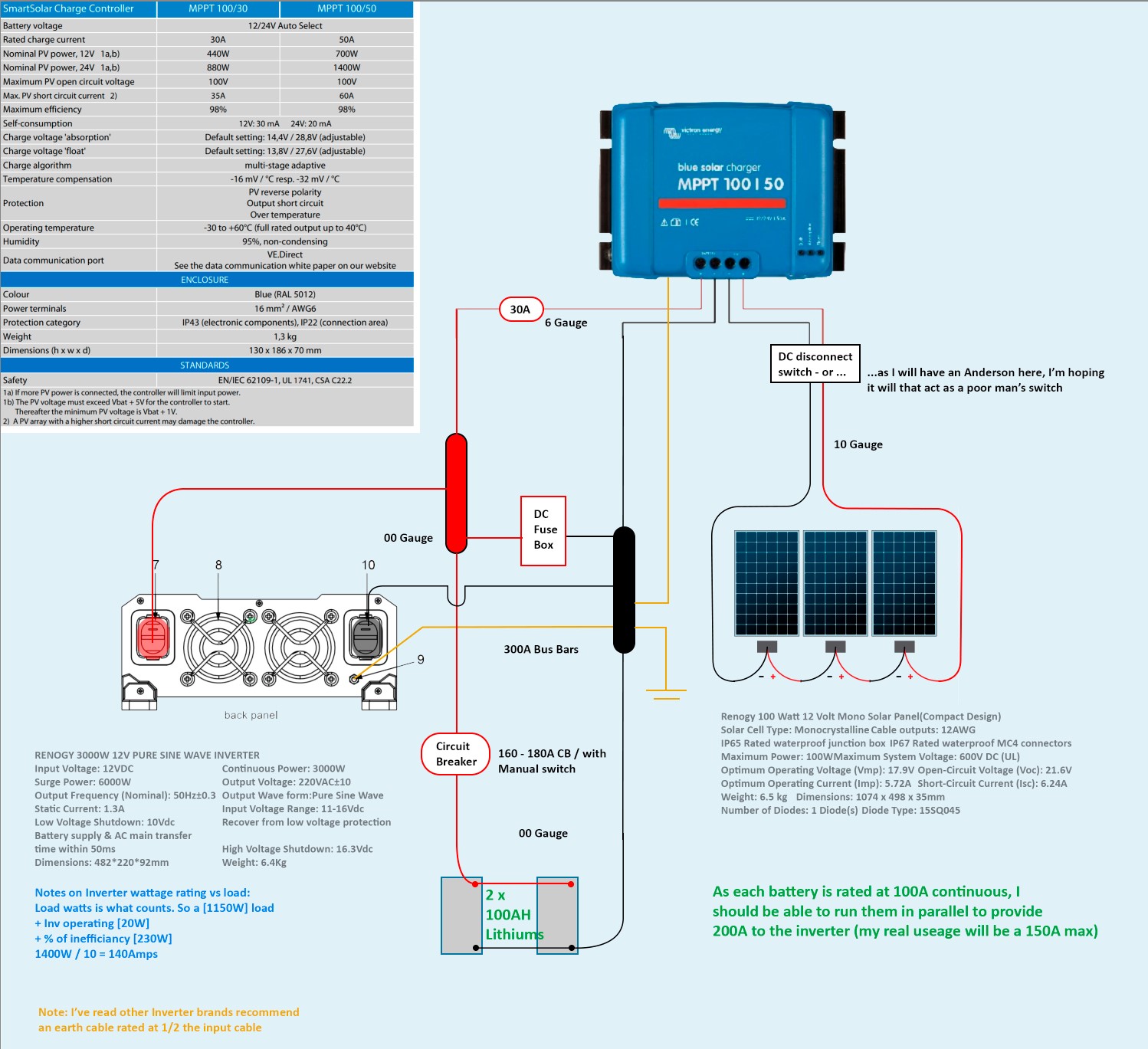
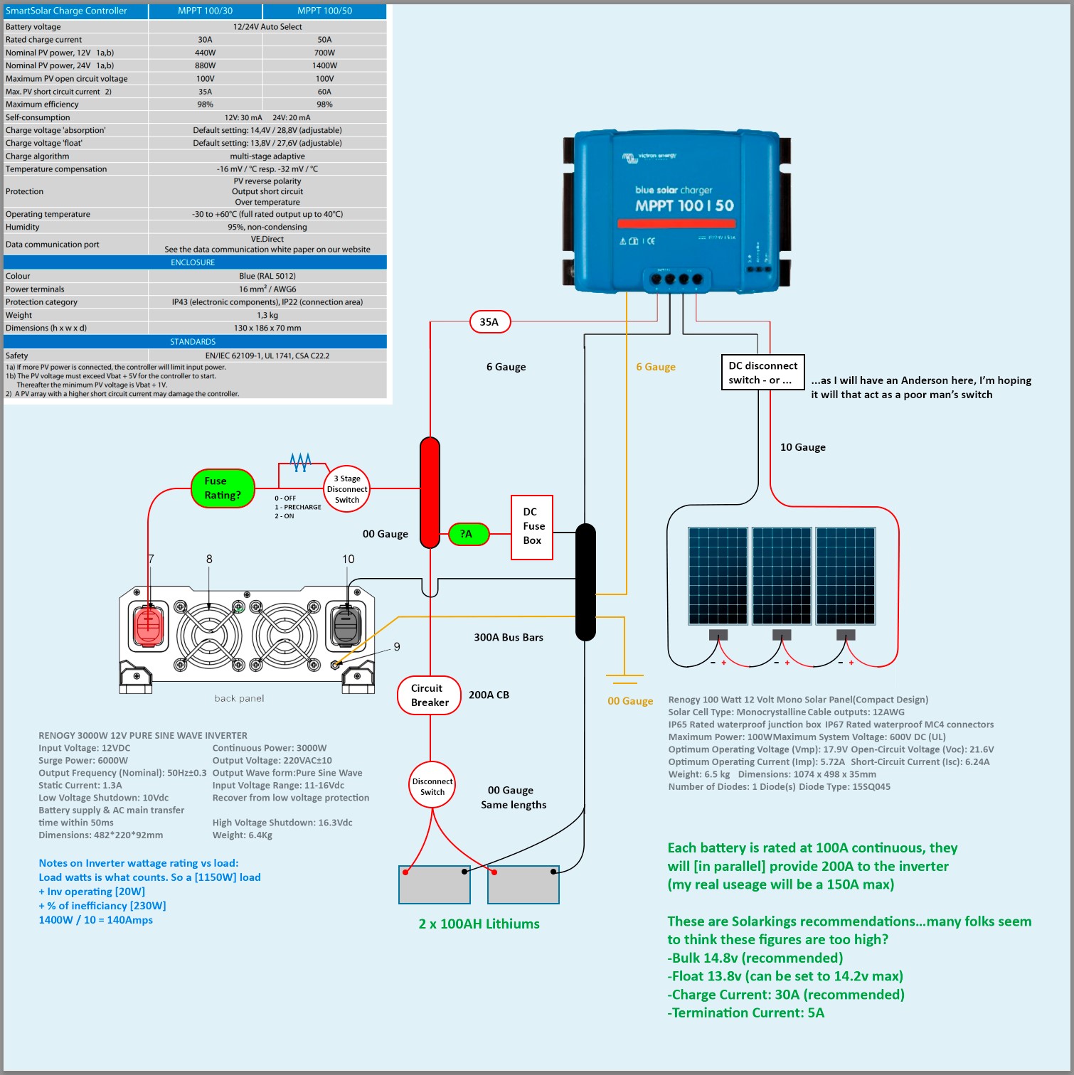
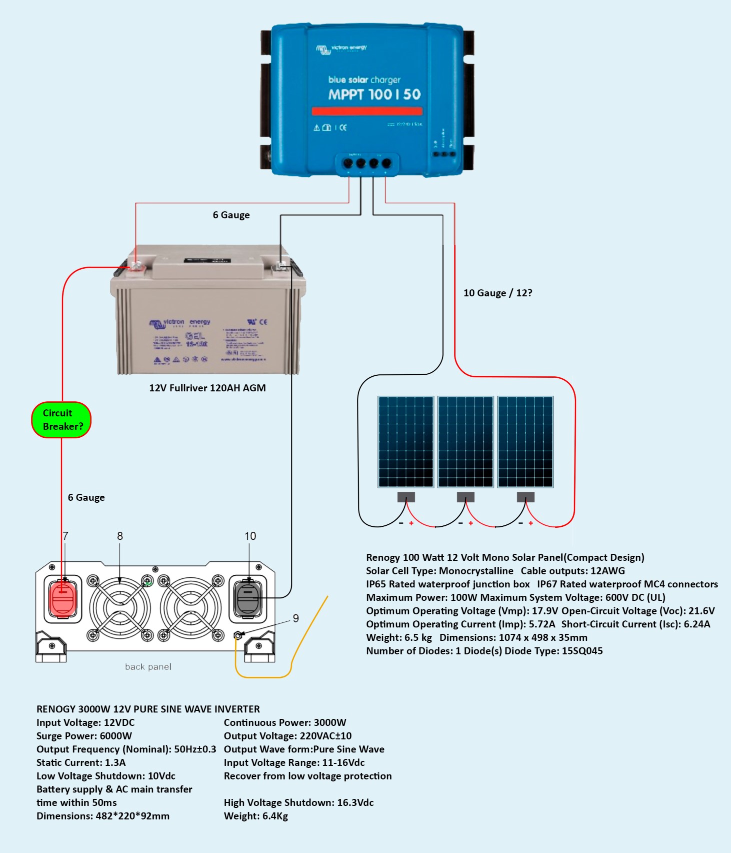
1. Should I have a circuit breaker (as depicted)? And/or, any other protective devices in the diagram - and if so, what type/rating?

2. The system will be contained within a car for 85% of the time, I assume I should Ground the Inverter and MPPT to the vehicle (wherever I can find good contact). Though, the other 15%, it will be completely standalone at a campsite without being grounded...which I assume is the case for many setups?

3. The Panels come with some 12 Gauge, I assume that's fine to run there on? 4. ...anything wrong with the setup, improvements, suggestions?

Many thanks in advance - I really appreciate it (particularly @seb71 for getting me on the path :) ).

MPPT SmartSolarsmart solar set-up helpsystem design
2 |3000

Up to 8 attachments (including images) can be used with a maximum of 190.8 MiB each and 286.6 MiB total.

3 Answers
seb71 avatar image
seb71 answered ·

The single 120Ah 12V lead-acid battery is massively undersized for a 3000W/12V inverter.


Use fuses on all positive wires connected to the battery.


Panel Voc is 21.6V so 21.6Vx3 = 64.8V => plenty of safety margin to the maximum 100V allowed by the 100/50 charger.


Isc = 6.24A, one string so 10AWG (~6mm2) should be fine for PV wires (since it's for a car, I assume they are not extremely long). Use a 10A fuse on the positive wire (CH10x38 gPV type) or one such fuse on each wire (one on positive wire, one on negative wire).

You can also add a DC disconnect switch, too (between the fuse(s) and the solar charger) - should be rated for at least 100V DC / 15A (for some safety margin). Should disconnect both the positive and the negative wires from the panel array.

Use a small connection box for these.

On the other hand, many connect the panels directly to the solar charger. Your choice.


The 100/50 solar charger can output 50A current to the battery/inverter, but with a 300W PV array, the maximum is about 25A. So you can use this 25A current to size the wires between the charger and the battery (and the fuse on this positive wire). 6 AWG should be fine (again, assuming not excessively long). You can even use 7 AWG (10mm2) since you won't reach 50A. Use a 32A fuse on the positive wire between the charger and the battery.


For the wires between the battery and the inverter, if sized for 3000W, that means about 250A. Massive current. Massive wires. 6 AWG is tiny for this.

Not really worth considering a 3000W inverter for 12V. Even for 24V, 3000W it is kind of big. This is 48V area.


You could/should include DC busbars in your design.

2 |3000

Up to 8 attachments (including images) can be used with a maximum of 190.8 MiB each and 286.6 MiB total.

peterb381 avatar image
peterb381 answered ·

So sorry for the long delay @Seb71, it wasn’t because I'm not extremely appreciative, but rather, your response really threw me by revealing a classic case of 'fools rush in' on my part; as in, I believe I possibly could run/draw 115-140A for 6mins from the Fullriver - but i'm likely to prematurely degrade the battery fairly quickly (now that I've read-up on a few things).

So I'm in a position where I'm desperate to get confirmation on the design now with your added suggestions—and whether changing to two Lithiums in parallel (200amps continuous) would allow me to run a device drawing 115-140A for 6-10mins?

victron-wiring-rev04.jpg

Worst case scenario, I will keep all that I have above, and just run my camp gear without this large load - but if it is possible to use 2 x lithiums to power the 140A, however - it may really entice me to make the switch.

Thanks again for all your help - Peter


2 |3000

Up to 8 attachments (including images) can be used with a maximum of 190.8 MiB each and 286.6 MiB total.

seb71 avatar image
seb71 answered ·

So the maximum load is under 1400W.


Still too much for a single 120Ah 12V lead-acid battery.

Two 100Ah LiFePO4 in parallel (or better in series) should be able to supply that power for 10 minutes (and even more).


LiFePO4 batteries are expensive. Most people use them with a BMS, which is also expensive. If you sink that kind of money into this system, really think about switching to at least a 24V system. If you already got the 12V inverter, sell it. The 3 panel string Voc is still high enough for a 24V battery. The charger can use a 24V battery, too.


You could also consider using the solar system (with the cheaper 12V lead acid battery) only for small loads and getting a generator for that 1400W load which only runs for 10 minutes.

Or if that load is an oven, change to propane.

6 comments
2 |3000

Up to 8 attachments (including images) can be used with a maximum of 190.8 MiB each and 286.6 MiB total.

peterb381 avatar image peterb381 commented ·

Thanks a lot @Seb71 - truly outstanding advice :)…so my battery was never going to cut it - therefore, I bit the bullet and purchased two Solarking Lithium 100AH's - please see revised design.

1. Although each battery is rated at 100AH continuous, should I make the CB a tad less just to be a little bit more gentle on them, or should I go with the specs and put a 200 there?

2. How to Earth: is my design with both earth's running to the bus bar, then to the car body from there correct, or should they run separately straight to the body? Also, what gauge should I use?

Hopefully this is close, for I need to be up and running by Thursday *fingers-crossed*.

A thousand thanks for all your advice. Cheers Peter

screenshot-2021-03-21-001232.jpg

0 Likes 0 ·
seb71 avatar image seb71 peterb381 commented ·

If you will use two batteries in parallel, that wiring arrangement is not the worst, but the best would be to use two positive wires of equal length between the positive busbar and each battery (with a fuse on each wire) and two negative wires of equal length between the negative busbar and each battery. In this arrangement it is important that positive wires are equal and negative wires are equal, but positive wires can be of different length compared with negative wires. And better use fuses here, not circuit breakers. And then add a battery disconnect switch.

Add a fuse on the positive wire between the positive busbar and the inverter. When you connect this fuse (or the inverter wire), first precharge the inverter capacitors using a power resistor or an incandescent light bulb.


Check the battery specifications, but normally LiFePO4 can be discharged with 1C without issues, so you can draw 100A from each 100Ah battery (200A in total from the 200Ah parallel battery bank).


Add a fuse between the positive busbar and the DC distribution box (place this fuse close to the busbar).


As a general rule: fuse rating/size is selected to protect the wire. So the current carrying capacity of the wire must always be higher than the current at which the fuse will blow.

Fuse rated current should be slightly higher than the current you expect, so that you don't blow the fuse under normal loads. But the wire must be able to safely carry higher current than that, as I said.


For grounding the solar charger case, you could use at least 9 AWG (6mm2). I would not use bigger than 5AWG (16mm2) here.

For grounding the inverter case, I think 5AWG (16mm2) should be fine.

For grounding the negative busbar, use a heavier gauge (use a leftover from inverter wire).

You could ground the charger case and the inverter case straight to the car chassis, but only if you are sure it's a whole metal body vehicle (so that various metal parts are actually in contact).


If you can, use wires with proper colors. At minimum, mark them at each end (and along the way for longer wires) with colored heat shrink tube or electric tape.

0 Likes 0 ·
peterb381 avatar image peterb381 seb71 commented ·

Hey @Seb71, first of all - *thanks again* - and I believe I've incorporated your suggestions correctly in my latest revision:victron-wiring-rev08.jpg

1-Just making sure you meant 00 Gauge for the -/Bar earth?

2-And, how many watts are we talking for the incandescent pre-charging (I like the idea of visually seeing the light dim once the caps are charged.)

3- …and, no doubt you're well aware i've been learning on the fly - and have made some pretty awesome mistakes here and there - but i'm hoping, I haven't made another one. My latest concern is the actual supply voltage from the MPPT - as I will most likely have it set between 14.5-14.8v (...not yet sure exactly, as I don't know what profile is best for the Solarkings), and i'm worried how those extra volts will effect my Dometic CFF45 12/24/240 fridge? Or am I needlessly worrying - for I can't find any information on safe boundaries, or max input, and/or whether it may get confused between 12/24 switching at 14+.

Anyhow, I really hope we're in the ball park now, for I'm becoming more and more embarrassed asking for your help…though I most certainly appreciate it - thanks a lot, Peter

0 Likes 0 ·
seb71 avatar image seb71 peterb381 commented ·

Battery wiring is not good.


Each negative wire should go from each negative battery terminal to negative busbar. If you will later add a shunt, use a small negative busbar before the shunt (and connect the negative wires from each battery) or connect both cable lugs on the battery side of the shunt (in general it is preferable to use only one wire lug on each bolt, but two are acceptable).


For the positive wires between the positive terminal of each battery and the positive busbar you have several options:

- use only a fuse on each wire (no battery disconnect switch in this case);

- use a fuse and a disconnect switch on each positive wire;

- use a fuse on each wire and an intermediary positive busbar and use a single battery disconnect switch between this intermediary positive busbar and the big positive busbar (or connect both wire lugs on this disconnect switch and skip the intermediary positive busbar).


If you notice, one thing I consider mandatory: fuses.


The fuse for the DC distribution box should be chosen to protect the wire, as explained. And the wire gauge should be chosen based on the current you will have.

I assume that your DC loads will not be close to the battery so you will place that DC distribution box some distance away (closer to your devices, so that you don't have to use lots of small wires to the battery).


1-Just making sure you meant 00 Gauge for the -/Bar earth?

Just because you already have that wire. It can be smaller. But at least 5AWG (16mm2).


2-And, how many watts are we talking for the incandescent pre-charging (I like the idea of visually seeing the light dim once the caps are charged.)

Whatever you have at hand. For instance a 230V/60W incandescent light bulb (wolfram/tungsten filament, not LED light bulbs) in a base with wires. Only use it temporarily before connecting the inverter to the battery, not a permanent fixture. No need to over complicate things.


I'll answer the charging voltages question on another reply.

0 Likes 0 ·
seb71 avatar image seb71 seb71 commented ·

Victron has many wiring examples you can look at, such as this one.

0 Likes 0 ·
seb71 avatar image seb71 peterb381 commented ·
3- My latest concern is the actual supply voltage from the MPPT - as I will most likely have it set between 14.5-14.8v (...not yet sure exactly, as I don't know what profile is best for the Solarkings)

LiFePO4 cells should never be charged above 3.6V (cell voltage).

A 12V (nominal) LiFePO4 battery has 4 cells.

So 3.6V x 4 = 14.4V. Never go above this when charging LiFePO4.


But it is not that simple. In certain cases you want to stay even under 14.4V.

Cells are never identical. Some are closer matched (in a factory built battery), some less so. And even if they are closely matched in characteristics, they might not be charged at the same State Of Charge.


You can have different cell voltages so if you reach 14.4V battery voltage, you can have one or more cells above 3.6V (and some below).


If your battery has a BMS, you must find out what that BMS does (if it does cell balancing or not; if it can disconnect the battery or stop the charger when a cell gets too high or too low, etc.).

Depending on that, you will have to set up the charger in a certain way (certain voltages).


You also need some protection for over discharging the cells. Avoid going bellow 3V (cell voltage) - that is under load.

Not sure if your inverter has any such settings or if your BMS can disconnect the battery to protect the cells for over discharging.


i'm worried how those extra volts will effect my Dometic CFF45 12/24/240 fridge

It should work fine at that max 14.4V.

0 Likes 0 ·

Related Resources

MPPT product page

VictronConnect manual

PWM or MPPT

MPPT calculator

MPPT codes

Additional resources still need to be added for this topic