question

bones83 avatar image
bones83 asked

LiFePo4 2s2p midpoints

Hi,

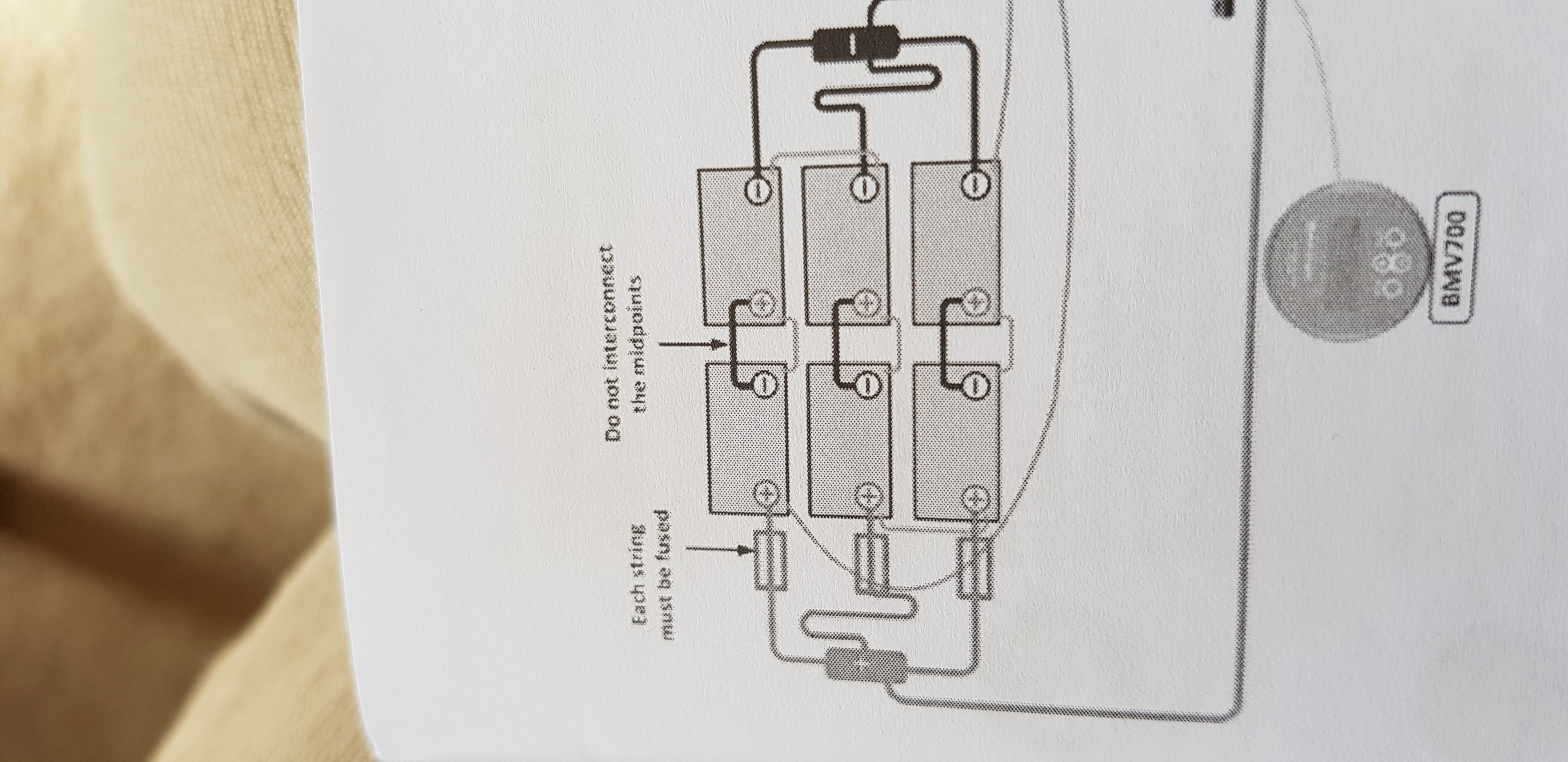
Can anyone tell me the reason that victron state not to connect the midpoints in a 2s2p Bank (to make 2p2s)?

Im having trouble getting my bank in balance, and i think temporarily connecting the midpoints for a cycle or two would help to bring them in line with each other.

Any feedback greatly appreciated =)


*edit - of course i would fuse this connection, rather blow a small fuse than have fireworks!

Lithium Battery
8 comments
2 |3000

Up to 8 attachments (including images) can be used with a maximum of 190.8 MiB each and 286.6 MiB total.

Jack Peters avatar image Jack Peters commented ·

Can you provide a link to the document where you read that?

It is hard to give a reason for a statement without context.

0 Likes 0 ·
bones83 avatar image bones83 Jack Peters commented ·

These pics are from the manual for my batteries, they are an old model, 12.8V, 90Ah non smart with btv leads for attaching to bms.

2021-03-01-085404.jpg

2021-03-01-085023.jpg

0 Likes 0 ·
bones83 avatar image bones83 commented ·

Just to clarify, I understand the risk in case of a bad cell, hence the fuse (thinking 10A initially and keep an eye on what happens). However I dont know if victron say this should not be done because of anything to do with the BMS. I dont want to compromise the ability of the BMS to function correctly!

0 Likes 0 ·
kevgermany avatar image kevgermany ♦♦ bones83 commented ·
It's to avoid imbalance between the left/right halves of the strings
0 Likes 0 ·
heartmindresearch avatar image heartmindresearch commented ·

I am having a substantially similar problem with new and matched strings of 200Ah 12v LiFePO4s in 2s2p, 24v.

I am using shore power charging with a Multiplus 24/3000/70-50 with veconfig'd default LiFePO4 settings and/or settings as low as 27.6V absorption and 26.8 float.

I have been around the houses and rearranged the strings and pairs, connected and unconnected midpoint. The cables are precisely measured, lugged and landed properly, bussed, fused and torqued.

Midpoint balance exceeds 2.0% as bulk transforms to absorption. And within a few minutes of disconnecting shore power and thereby stopping absorption, the midpoint balance goes to 0.1% or under and all batteries come within a 0.1V of each other.

screen-shot-2021-12-09-at-70538-pm.png


Can anyone shed light on this?

screen-shot-2021-12-10-at-71657-am.png

Thank you! HRx

0 Likes 0 ·
bathnm avatar image bathnm heartmindresearch commented ·

@heartmind.research The cell balancing within the battery only kicks in at something like 13.8v. Therefore if your absorption charge is not the default 28.4, your cells will not balance as the voltage is not high enough. If very unbalanced it might take a few cycles for the them to become balanced. I have read that extending the absorption phase from 2hours to something longer as long as there is only a few amps will also help balance the cells. I would say that any changes to longer absorption time should be checked with your supplier/distributer.

Also I would not connect the midpoints. The 2 batteries in series will over time balance themselves.

I have the same 4 x 200Ah in a 2S2P setup and no interconnection of the midpoint, and cells as reported by the VictronConnect App staying balanced just fine. All charging is set to Victron defaults.

1 Like 1 ·
heartmindresearch avatar image heartmindresearch bathnm commented ·

screen-shot-2021-12-10-at-51147-pm.pngI appreciate your reply. I will disconnect the midpoint as I wait for the "Battery Balancer" to arrive. When I read Victron's blog re the balancer, they were describing the problem I am having. I have returned to 28.4 absorption, 27.0 float, 99% efficiency, 1.01 Peukert, but 15 minutes absorption, on my SmartSolar and SmartShunt. I will expand that to default 2hrs. My Multiplus is returned to same but I saw no place for Peukert's on VE.CONFIG. I will look again and return to longer absorption there too. I should have the balancer by Wednesday. Allegedly, the balancer will solve the problem.

0 Likes 0 ·
heartmindresearch avatar image heartmindresearch heartmindresearch commented ·

screen-shot-2021-12-19-at-25212-pm.png
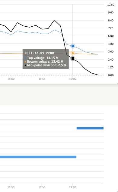
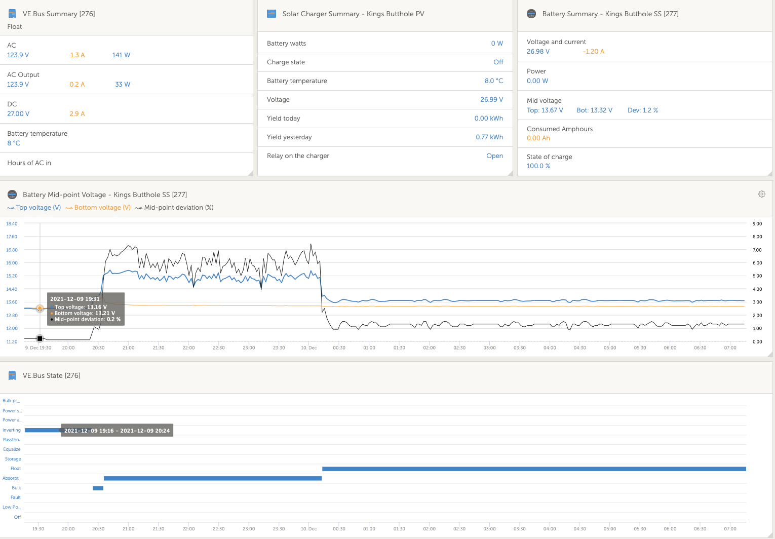
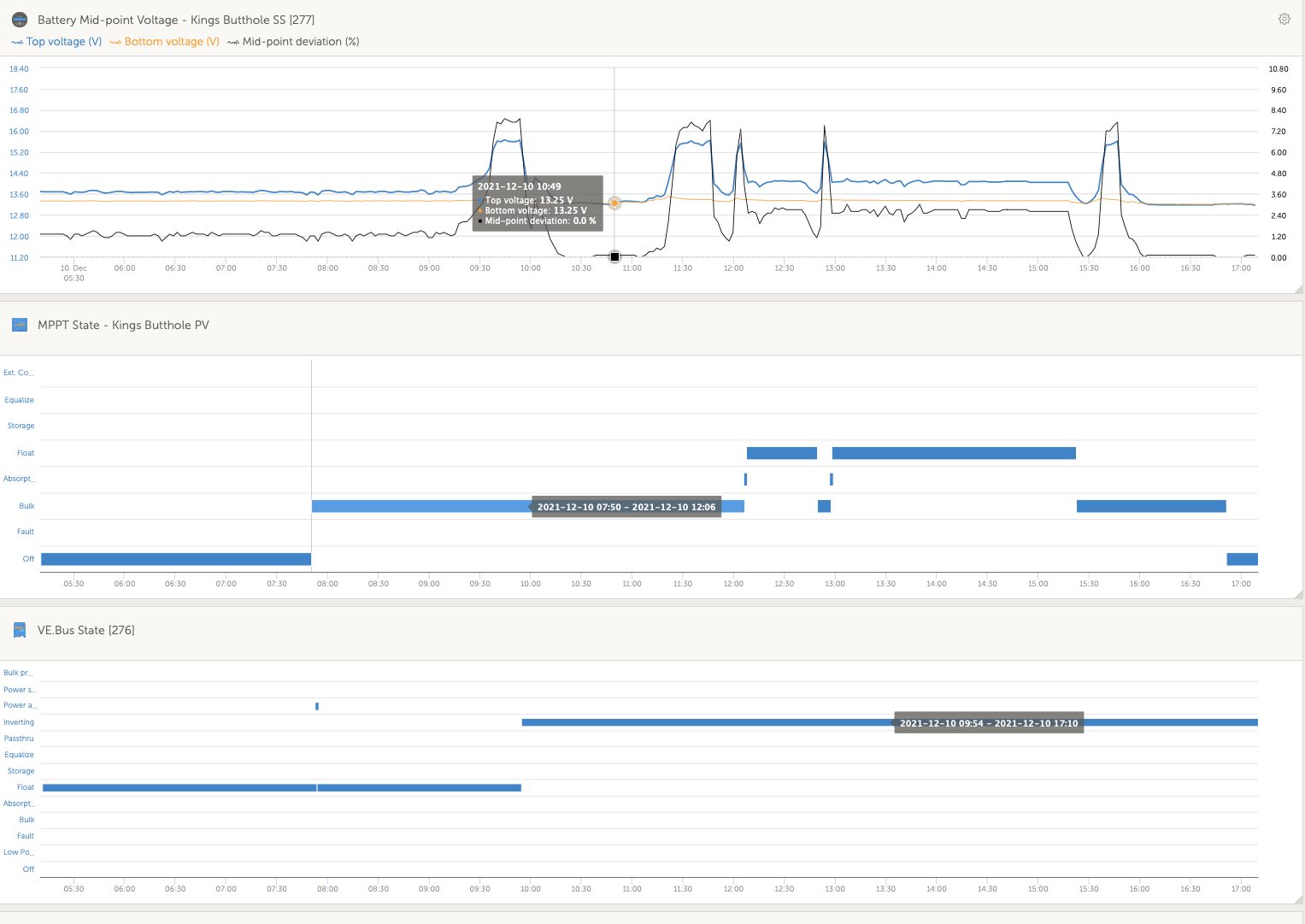
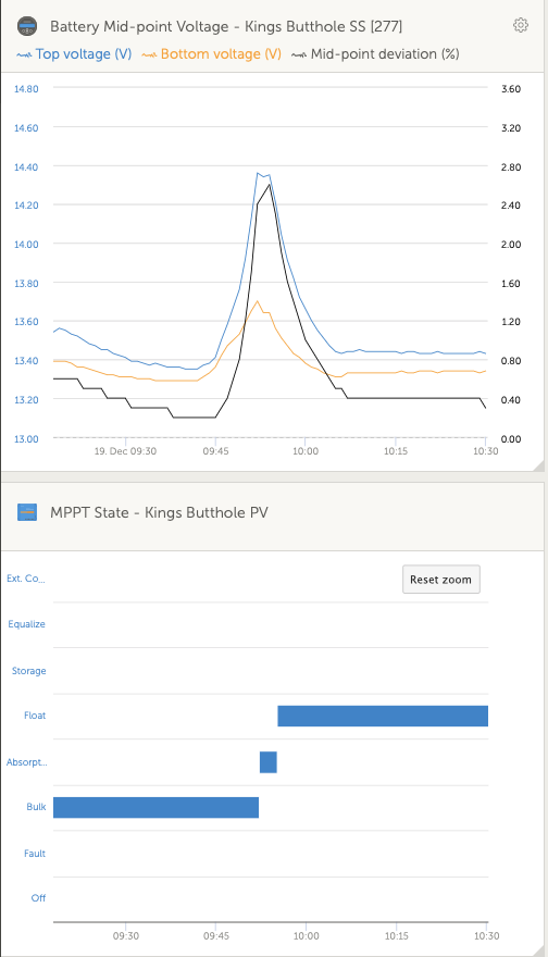
The balancer has only reduced the problem. I am still ramping to 2.80% divergence on the tail of absorption. Within minutes of switching to float, the divergence is under 0.5%. HRx

0 Likes 0 ·
6 Answers
seb71 avatar image
seb71 answered ·
Im having trouble getting my bank in balance, and i think temporarily connecting the midpoints for a cycle or two would help to bring them in line with each other.

If that's the purpose, better connect only two batteries (in series) at a time for a few days. So only one battery string.


When you put the two strings in parallel again, make sure that they are at at the same voltage/SOC.

2 |3000

Up to 8 attachments (including images) can be used with a maximum of 190.8 MiB each and 286.6 MiB total.

bones83 avatar image
bones83 answered ·

Thanks for the response, but I am fairly sure that with two in series I will experience exactly the same problem, at the moment with 2s2p I have the voltage of one battery in each series string rising rapidly during absorbtion. I have set a low absorption voltage of 27.6V and even so one battery in each series reaches around 14.2 while the other ends up around 13.5. I'm pretty sure that the lower voltage battery is not charging at this point

Thanks for reading =)

2 |3000

Up to 8 attachments (including images) can be used with a maximum of 190.8 MiB each and 286.6 MiB total.

Daniël Boekel (Victron Energy Staff) avatar image
Daniël Boekel (Victron Energy Staff) answered ·

To balance: put all batteries in parallel, and charge with a 12V charger (see manual).

3 comments
2 |3000

Up to 8 attachments (including images) can be used with a maximum of 190.8 MiB each and 286.6 MiB total.

bones83 avatar image bones83 commented ·

This is what I would do, except I have no suitable 12v charger, the only charging source I have available is a multiplus 24V.

0 Likes 0 ·
mvas avatar image mvas bones83 commented ·

If you do not have a 12 Volt Power Supply, then how did you perform the INITIAL Balance?

0 Likes 0 ·
bones83 avatar image bones83 mvas commented ·

I commented in the wrong place - see above =)

0 Likes 0 ·
mvas avatar image
mvas answered ·

If you do not have a 12 Volt Power Supply, then how did you perform the initial BALANCING of the battery bank?

12 comments
2 |3000

Up to 8 attachments (including images) can be used with a maximum of 190.8 MiB each and 286.6 MiB total.

bones83 avatar image bones83 commented ·

@mvas - I have a very small car battery charger (3.5A max) with no lithium mode, i used this on each battery individually and I literally sat and watched the voltage until it reached 14.2V then manually disconnected and connected a small (1Amax) power supply set at 14.2V for around 8 hours per battery. I could do this again, but I think I will have the same problem when connecting them in 2s2p afterwards as everything is the same as before.

Alternatively I could put all 4 batteries in parallel and charge with the small car charger, but I think it will take too long for me to babysit them the whole time, and I dont want to risk the charge voltage rising to the limit of the charger (i guess around 14.6V)

The imbalance in the batteries only appears at the top end of charging, once the batteries get close to absorbtion voltage.

When testing under a large-ish discharge load (2.2kw), the batteries stayed within 0.05Volts of each other.

The batteries are around 6 years old.

I received these batteries, a multiplus 24/3000/16, a color control, and the cabling that was used in their original installation.

I found the cable lugs had not been secured properly (just taped on!) with some just pulling off under very light pressure, I also found the multiplus firmware to be corrupted, so I am quite sure that these batteries have experienced some very bad conditions and probably were not initially balanced and/or maybe never equally charged in their original installation.

Because of this I think that the batteries have all aged differently, and may have differing internal resistance.

This may mean that I need to go through a balancing procedure much more regularly than usual, and temporarily connecting the midpoint to make 2p2s when required seems like a simple solution.

Thanks for reading, sorry it's such an essay but I realised maybe a thorough explanation of the situation was required =)

Any help or feedback greatly appreciated!

0 Likes 0 ·
mvas avatar image mvas bones83 commented ·

6 year old batteries may be showing some signs of wear and tear.

You do need to raise the voltage of the lower voltage cells, before putting them in parallel with the the higher voltage cells. You can charge the lower voltage cells ( bring them UP ), while putting a load on the higher voltage cells ( bring them down) BEFORE connecting them in parallel.

I do not agree that you can charge each cell individually and then call them "balanced".

Connect all four (4) cells in parallel and charge them, with the exact same voltage, with equal length connections, simultaneously as one large block = Balanced.

Have you considered adding a "2S Battery Balancer" across your series connected batteries? I believe that device can move, up to 1 amp, when a 50 millivolt deviation exists between the upper bank and the lower bank, while still charging at 24 Volts.

0 Likes 0 ·
bones83 avatar image bones83 mvas commented ·

Ok, I charged them individually as that's what the user manual suggested to do before connecting in series or parallel.

I did look at battery balancers, but they seem fairly expensive - does connecting the midpoints not do exactly the same job? If I have a 10A fuse inline then I can move up to ten amps if necessary for the price of a piece of cable. Or I can use a smaller fuse if 10A is too much to be safe.....

I will buy a 2s balancer if necessary but still am unsure why connecting the midpoint is not allowed =)


0 Likes 0 ·
seb71 avatar image seb71 mvas commented ·

Those are batteries, not cells. Each of his four LiFePO4 12V battery has 4 cells inside.


Ideally would be to charge all 16 cells in parallel, but that would require removing them from the batteries.

0 Likes 0 ·
bones83 avatar image bones83 seb71 commented ·

I wish this was an option, but until they are not usable as a pack I cant bring myself to cut them open! =)

0 Likes 0 ·
seb71 avatar image seb71 bones83 commented ·

I know. That's why I said it's not that big of a difference to charge 2 batteries in series (so 8 cells in series) compared with charging only 1 battery (4 cells in series), while using the VE.Bus BMS, which should perform some cell balancing (or at least I assume it does cell balancing).

If the BMS performs cell balancing, that happens only on the top portion of the charging curve.

For LiFePO4 cells you should keep them under 3.6V.

Be careful: 14.4V battery voltage does not necessarily mean that you have inside 4 cells with 3.6V each.


In the attempt to balance the cells, if you charge two batteries in series and you notice a big voltage difference between the two 4-cell batteries, you could manually discharge only the battery with the high voltage. Use some power resistor or incandescent light bulbs. Or some 12V appliance you might have.

Maybe the weaker battery will eventually "catch up".


Keep in mind that you can either balance the cells at the top (fully charged) or at the bottom (fully discharged). Not in-between.

And when using a BMS, the only option is to balance the cells at the top.

This means, if the cells are not perfectly identical (and they never are), they will not be balanced at the bottom. So set a safe limit for discharge, otherwise you will undo the top balancing and potentially even damage the cells (if the BMS does not act in time as it should).

0 Likes 0 ·
bones83 avatar image bones83 seb71 commented ·

I may be understanding it wrong, but I think the actually cell balancing happens inside the pack, and the external Vebus bms is just receiving data from the cells regarding temperature and voltage in order to control chargers and loads.

I think the cell balancing is only between cells of the same pack, this is why I think that 2s charging will still show the same symptom! Maybe someone who knows could let us know. =)

I'm also still curious why midpoint connection cannot be made, the bms will still monitor cell voltages and cut the charge if any cell reaches 4V or cut the load if any cell drops to 2.8V......

0 Likes 0 ·
seb71 avatar image seb71 bones83 commented ·

Yeah. By "VE.Bus BMS" I mean the components inside the battery and the external device. As a "system".


If you have a 2s2p pack and bridge them mid-point, if one battery has higher internal resistance, the current will flow mostly through the other one in parallel with it.

Same problem with strings in parallel without a mid-point connection, but then at least each string has the same current. So not as bad compared with the other case.

0 Likes 0 ·
bones83 avatar image bones83 bones83 commented ·

Ok, thanks for the advice! I guess I will have to try and top balance them in 4p with my 1 amp charger, which may take a long time! I tried to set a disconnect for around 20% (12.9V if the chart I found is to be believed), but the multiplus wouldn't let me unless my reconnect was at I think 13.9 if I remember correctly! So instead I have set the low battery alarm @ 12.9V, the LVD @ 12.OV, and the reconnect @ 13.0V, maybe I will move the LVD and reconnect up a bit when I install the system for actual unattended use....

0 Likes 0 ·
bones83 avatar image bones83 bones83 commented ·

The balancing with the bulb sounds a bit like I might be chasing my tail the whole time! =)

0 Likes 0 ·
seb71 avatar image seb71 bones83 commented ·

12V for battery (so 24V for the pack) LVD should be fine when using well matched cells.

But if one of your 4 batteries is very different then the other 3, then 24V might be too low.

In order to correctly set this, you would have to be able to see/measure each cell voltage, but unfortunately you can't for your batteries.

So you might want to set a bigger safety margin for discharging.

0 Likes 0 ·
bones83 avatar image bones83 seb71 commented ·

After much deliberation I decided to try the midpoint link whilst charging, yesterday without the link I had a voltage difference of 500mV between the highest and lowest packs towards the end of absorbtion and on float, today with the midpoint link in place my voltage difference at the the end of absorbtion and on float was only 20mV! I have now removed the link and will try the same tomorrow with the recommended absorbtion voltage of 28.4V =)

0 Likes 0 ·
mvas avatar image
mvas answered ·

If the BMS begins the Top Balance process at 14.2 Volts, then don't you need 28.4 Volts across the battery bank?

But, you you only have 27.8 Volts for Absorb?

Could this have allowed one or more cells to get way out of balance and that allowed the overall battery voltage to also get out of balance?

1 comment
2 |3000

Up to 8 attachments (including images) can be used with a maximum of 190.8 MiB each and 286.6 MiB total.

bones83 avatar image bones83 commented ·

I originally had absorb set at 28.4 for their first charge after the initial balance, but found the voltage in absorbtion had risen to 14.5 in two of the batteries. I then reconfigured them so the two weaker batteries were in series with each other and discharged them to 26V after leaving them overnight. For this (second)charge I decided to try a lower voltage absorb to see if the imbalance would still occur if I try to only charge to around 90%. The batteries are old and I wont be charging them to 100% anyway once I build my system.

0 Likes 0 ·
seb71 avatar image
seb71 answered ·

That's why I wrote to charge (with your 24V Multiplus) 2 batteries in series at a time and see if the cells get more balanced ("more equal").


Not as good as charging each battery alone (or all 4 in parallel), but better than charging the 2s2p bank.


When you get your MPPT, that could charge one battery at a time (or all 4 in paralel), but I don't know if you can still somehow use the VE.Bus BMS in that configuration (without a 12V Multiplus). You could wire the "Charge disconnect" to the MPPT remote turn off, but I don't know if the VE.Bus BMS works stand-alone.

2 comments
2 |3000

Up to 8 attachments (including images) can be used with a maximum of 190.8 MiB each and 286.6 MiB total.

bones83 avatar image bones83 commented ·

I had the bms connected (so I could see temperature or overvoltage warning) when I originally tried to balance with the car charger. Everything lit up ok so I assume it will work stand alone.

0 Likes 0 ·
bones83 avatar image bones83 commented ·

I'll definitely try this once I get my mppt, I have other projects to finish first so this wont be for quite a while! At the moment I'm testing the batteries to see how they perform before I buy anything as they are old and I think have been installed badly in their previous life =)

0 Likes 0 ·

Related Resources