question

sieade245 avatar image
sieade245 asked

Multiplus under-reading battery voltage

Hi guys. I have an 800AH battery bank connected to Multiplus compact 24/1600/40. Everything is working for over a year now. Theres 7m distance between batteries and multiplus so I used 35mm cable. I calculated volt drop over this distance would be around 0.3-0.4V and this is what I'm measuring however the multiplus is measuring around 0.7V lower than the battery terminal voltage. So for example, right now I have an 80% discharged bank which is inverting at 1200W (I've set it lower than max to increase battery life). My battery voltage is 24.7V, no issues there. The multiplus sees 24.0V. I've measured the voltage at multiplus and it is 24.3V, which ties up with my volt drop calculations. Again, no issues as the system works ok.

But, the only reason it does it that when I installed it, I noticed that the multiplus was shutting down early due to low voltage. I couldn't see any way to offset the voltage in the software. I'm using dynamic voltage adjustment and also temp sense. On my multiplus, there is no voltage sense terminals which would likely correct for this issue. Due to this, I had to "manipulate" the default voltage settings in the ESS assistant dynamic voltage page. I set all of them to 0.7V lower than the default values, so cut off at 24V becomes 23.3V etc. The only problem is...at lower current draw, the volt drop decreases so this could result in the battery potentially becoming dangerously discharged.

Now obviously, the ESS system uses SOC instead of terminal voltage to work out when its going to stop discharging and this has never been a problem since I changed the values....but it kinda seems like a work around and I've never really gotten to the bottom of why the multiplus is under-reading by the extra 0.3-0.4V in the first place. I think voltage sense cables would correct this but I have no where to connect them to and I don't really want to spend more money on a BMV which I imagine would also fix the issue.

Does anyone else have any ideas how to correct for this? I could increase my cable size to 50mm or 2 pairs of 35mm (don't fancy trying to fit 70mm in my DC breaker box) but this will only fix the volt drop in the cable and I would still have the problem with the remaining 0.3-0.4V. Is there a setting I've missed in the software maybe?

MultiPlus Quattro Inverter ChargerCCGX Color Controldc system
2 |3000

Up to 8 attachments (including images) can be used with a maximum of 190.8 MiB each and 286.6 MiB total.

4 Answers
Guy Stewart (Victron Community Manager) avatar image
Guy Stewart (Victron Community Manager) answered ·

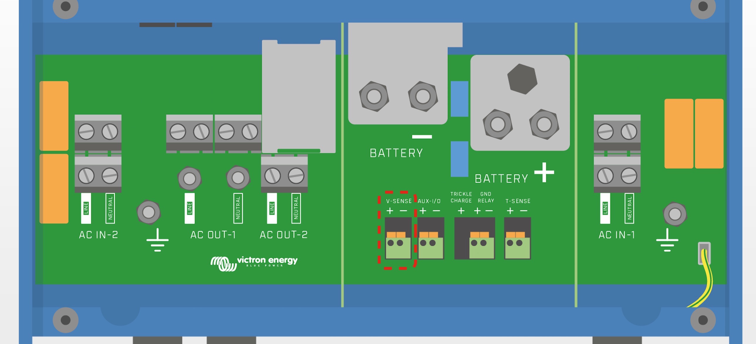
It doesn't sound like you are using the Battery Voltage sense terminals of your Multiplus?

See the manual section 4.4.2 Voltage Sense -

4.4.2 Voltage Sense

For compensating possible cable losses during charging, two sense wires can be connected with which the voltage directly on the battery or on the positive and negative distribution points can be measured. Use wire with a cross-section of 0,75mm2.


During battery charging, the MultiPlus will compensate the voltage drop over the DC cables up to a maximum of 1 Volt (i.e. 1 V over the positive connection and 1 V over the negative connection). If the voltage drop threatens to become larger than 1 V, the charging current is limited in such a way that the voltage drop remains limited to 1 V.


2 |3000

Up to 8 attachments (including images) can be used with a maximum of 190.8 MiB each and 286.6 MiB total.

sieade245 avatar image
sieade245 answered ·

Guy. Thanks for the reply but I don’t think you have read my post fully. The 1600w multiplus does not have any voltage sense terminals. That’s my problem!

1 comment
2 |3000

Up to 8 attachments (including images) can be used with a maximum of 190.8 MiB each and 286.6 MiB total.

Right you are, the manual has now been updated accordingly to remove reference to that feature for those models.

0 Likes 0 ·
ben avatar image
ben answered ·

Regarding increasing cable size, as you mention, that won't help you with other resistive losses that you can't change, like fuses or other interconnect points.

Regarding BMV+Venus, that is one way to do it: you can let the BMV probe the voltage, and use the distributed voltage feature in Venus to propagate that value to your Multiplus. You have to buy this stuff, of course.

However, you talk about how you have used the dynamic voltage feature in ESS. My recollection is that that feature lets you set cutoff voltages at a range of current values. Is that what you are seeing? If so, why not simply adjust the cutoff values (which you are already using to compensating) back closer to zero delta on the lower current values. That should address your concern, I think?

2 |3000

Up to 8 attachments (including images) can be used with a maximum of 190.8 MiB each and 286.6 MiB total.

sieade245 avatar image
sieade245 answered ·

Hi Ben. Thanks for the idea. I think that will work!

2 |3000

Up to 8 attachments (including images) can be used with a maximum of 190.8 MiB each and 286.6 MiB total.