question

peternielsen avatar image
peternielsen asked

Charging LiFePo4

Hi,

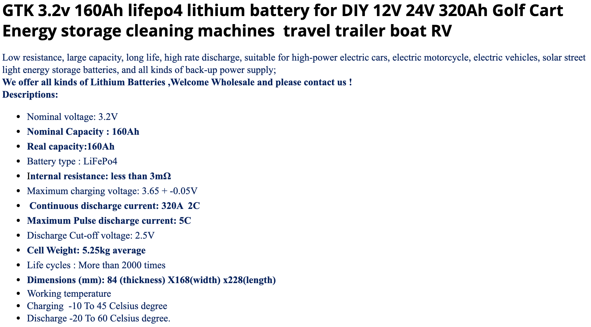
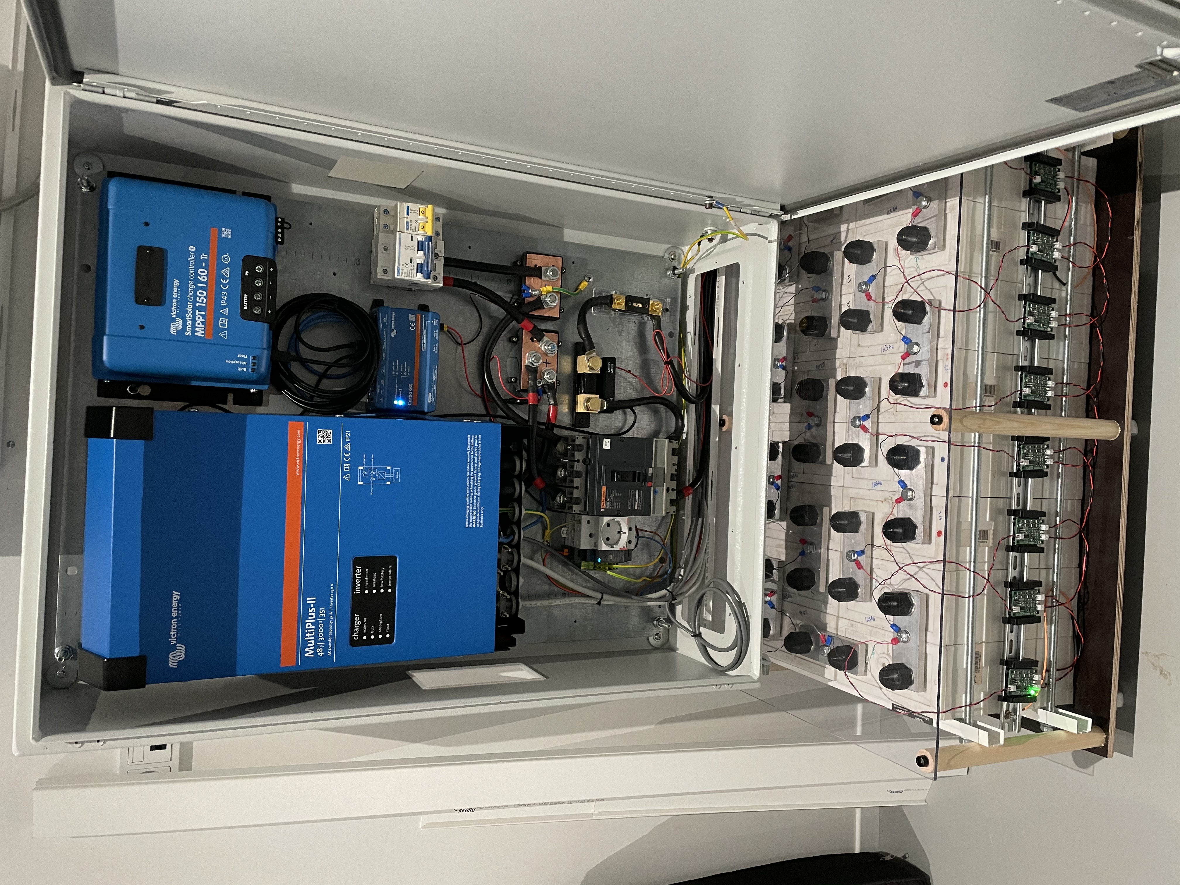
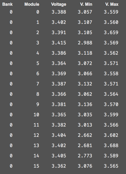
I have a 16S LiFePo4 160Ah as with following data :

1612264669187.png

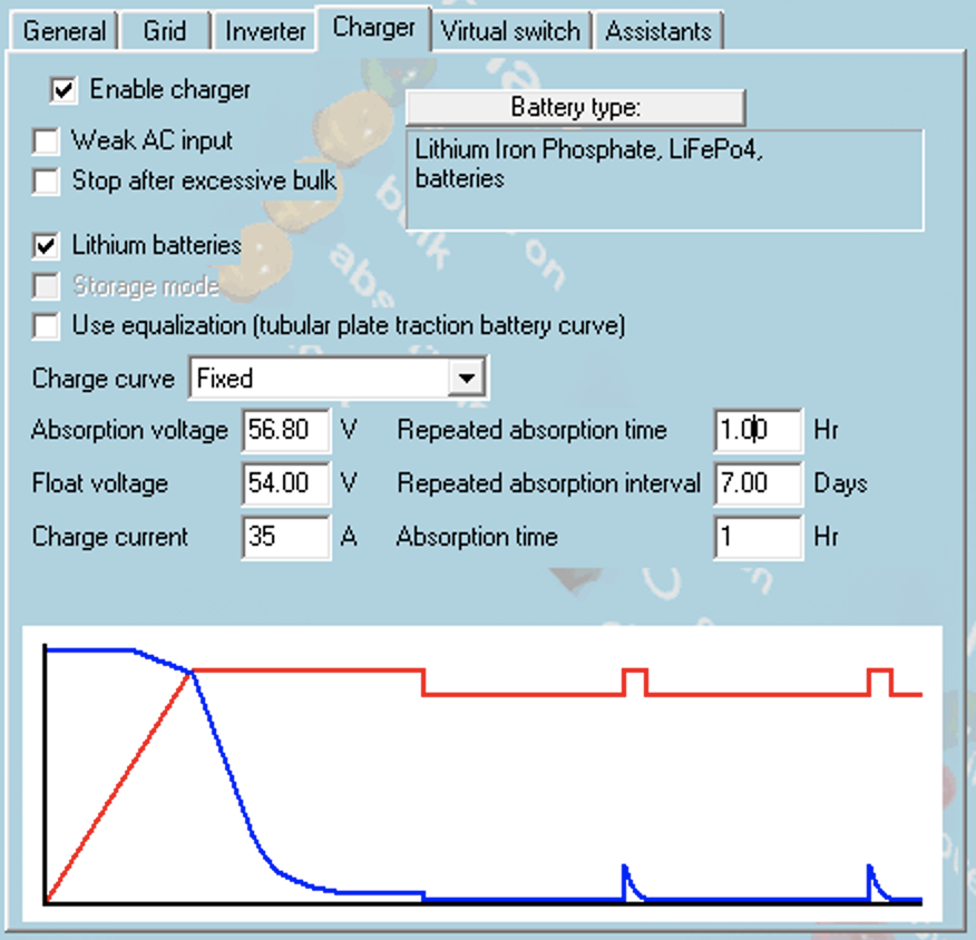
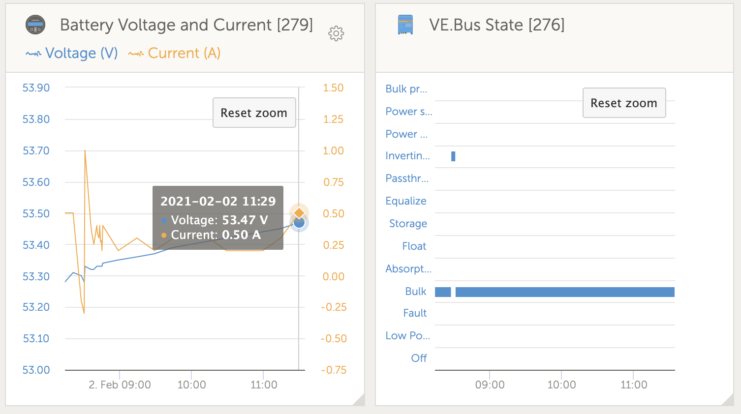
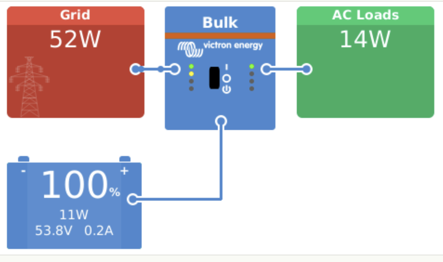
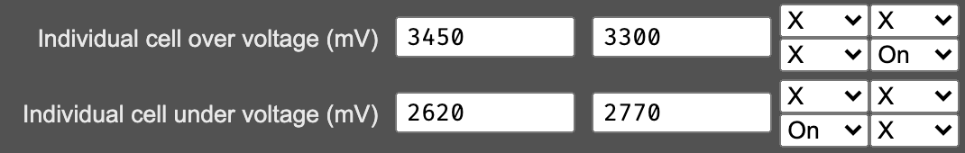
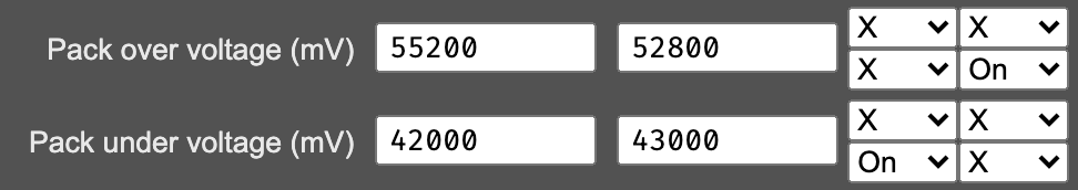
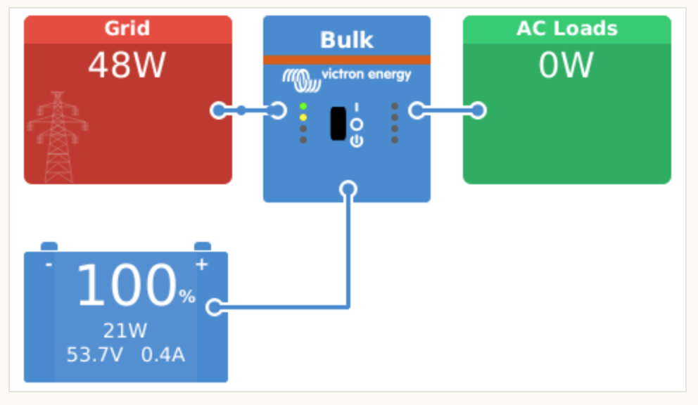
In VE.Config i have left everything default for LiFePo4 but i am not sure it's correct. Right now the battery has been in Bulk for 3-4 h but should it not charge it to 56,8V per the default settings ? Does everything look fine to you ?

1612264844165.png

1612264868798.png

1612264979499.png

Multiplus-IILithium Battery
1612264669187.png (225.8 KiB)
1612264844165.png (255.6 KiB)
1612264868798.png (90.7 KiB)
1612264979499.png (136.5 KiB)
2 comments
2 |3000

Up to 8 attachments (including images) can be used with a maximum of 190.8 MiB each and 286.6 MiB total.

klim8skeptic avatar image klim8skeptic ♦ commented ·

A handful of things

As previously mentioned, solid links between cells = bad.

Cell strapping/reinforcement needs to be positioned towards the middle of the cell to limit cell expansion.

Cell data seems to be noted per cell, Ah and voltage data.

Thin wires between cells and balancers. balancers placed on the back of the battery pack....

TBC..


0 Likes 0 ·
peternielsen avatar image peternielsen klim8skeptic ♦ commented ·
solid links between cells = bad.

Yes noted, i may want to change that at a point in time.

Cell strapping/reinforcement needs to be positioned towards the middle of the cell to limit cell expansion.

I have both at the bottom and at the top but i can move one of them to the middle if that is better.

Cell data seems to be noted per cell, Ah and voltage data.

You mean the hand writing on the cells ? Yes they have been capacity tested once then it was written on them the capacity.

Thin wires between cells and balancers. balancers placed on the back of the battery pack....

The cables are just fine for 1A current, i see no problems there neither can i see a problem the balance modules are just by the cells e.g some are on the back and some are on the front. The only thing is inconvenience to change something but that is not so bad since the battery pack is on wheels.

0 Likes 0 ·
5 Answers
seb71 avatar image
seb71 answered ·

Can you monitor or measure cell voltages?

Does it have a BMS?


You could slightly lower the charging current to 32A (0.2C).

Maybe other changes, depending on the answers to the above questions.

1 comment
2 |3000

Up to 8 attachments (including images) can be used with a maximum of 190.8 MiB each and 286.6 MiB total.

peternielsen avatar image peternielsen commented ·

Yes i can, here is the output right now :

1612265974899.png

and here are the rules i run with right now :

1612266007482.png

1612266026689.png

However not sure they are correct yet.

0 Likes 0 ·
1612265974899.png (248.3 KiB)
1612266007482.png (26.1 KiB)
1612266026689.png (23.9 KiB)
seb71 avatar image
seb71 answered ·

Does your BMS perform cell equalization at the top? If yes, you have to allow it to reach there.

3.45V is too low as cell over voltage (top limit) if cell balancing is done at over 3.5V for instance.


2.62V cell voltage is also too low (same for pack under voltage value).

You could set a 3V cutt off limit (so 16x3V=48V) in the inverter and slightly lower in the BMS (as a safeguard), but not as low as 2.6V cell voltage. This is in order to not completely discharge your cells (down to 0% SOC).


Also, with the current settings, you will never reach Absorption voltage set in the Inverter/charger. The BMS stops the charging at 55.2V (or when first cell reaches 3.45V - so the pack voltage is even lower than 55.2V at that moment) and the Absorption voltage is set at 56.8V.


79 comments
2 |3000

Up to 8 attachments (including images) can be used with a maximum of 190.8 MiB each and 286.6 MiB total.

peternielsen avatar image peternielsen commented ·

Yes the BMS does Passive balancing.

It's exactly the knowledge i was looking for. I will make the changes now.

0 Likes 0 ·
peternielsen avatar image peternielsen commented ·

Which one of the cut off limit i should set to 48V ?

1612273772298.png

0 Likes 0 ·
1612273772298.png (2.9 KiB)
seb71 avatar image seb71 peternielsen commented ·

You could try something like this and adjust later, if necessary:


0.005C = 49.2V

0.25C = 48.7V

0.7C = 48.2V

2C = 48.0V

0 Likes 0 ·
peternielsen avatar image peternielsen commented ·

So i tried to make an overview and what happens on the inverter and the BMS. What do you think of these now ? What do i need to correct ?

BMS Bypass value : 3500mV


Trigger value Reset value Inverter action
Individual cell over voltage (mV)
3700 3600 Disable charger
Individual cell under voltage (mV) 2950 3000 Charge only
Pack over voltage (mV)
58000 57000 Disable charger
Pack under voltage (mV)
47200 48000 Charge only


The reset value is described as following :

Rules are triggered when the relevant value meets or exceeds the 'trigger' value. The rule will only disable when the value then passes the 'reset' value. This can help prevent relay clatter and rules firing on/off rapidly.

I am not sure the reset values are correct either.


VE.Config settings :

Cut off voltage for dischare current of

Discharge Voltage
0.005 C 49.20 V
0.25 C 48.70 V
0.7 C 48.20 V
2 C 48.00 V


Charger
Absorption voltage 56V
Float voltage 54.00
Charge current 35A
Repeated absorption time 1.00h
Repeated absorption interval
7 days
Absorption time 1.00h


Sustain : 50.00 V
Inverting is allowed when 1.20V over cut off.

0 Likes 0 ·
seb71 avatar image seb71 peternielsen commented ·

Individual cell over voltage (mV) 3700

Too high. Do not go over 3.6V cell voltage for any reason.


Is it explained in the BMS manual at what cell voltages it performs equalization?

The proper top values ("over voltage") from the first table (from BMS, for cell and for the battery pack) depend on how your BMS performs equalization.

Also the "Absorption voltage" value set in the Inverter/charger depends on this.


I gave 3.5V just as an example. You have to determine this from your BMS manual.


For the bottom values ("under voltage"), maybe 2900mV for cell (with "reset" at 3150mV) and for battery multiply with 16 the cell voltages. But take note that since cells are not perfectly identical, the cell values will matter.

-------

Dynamic cut-of voltages - I already wrote about them.

-------

Absorption voltage - set it slightly lower, at 55.2V (unless this is too low for BMS to perform equalization).

-------

Float voltage - set it at 53.6V

-------

Charge current at 0.2C, so that means 32A for your 160Ah cells.

-------

Repeated absorption time - should be ignored if the battery is set to Lithium ("Lithium batteries" box checked).

--------

Repeated absorption interval - should be ignored if the battery is set to Lithium.

-------

Absorption time - initially leave it at 1h, but monitor the charging current during Absorption stage, to see the value at the "absorption time" stage finish.

The current will decrease during Absorption stage (which is a Constant Voltage/CV stage).

The aim is to end Absorption when the current decreased to about 0.05C, so in your case 0.05x160 = 8[A].

If the current after 1 hour (since the Absorption stage started) is still more than 8A, then increase the Absorption time. The problem is that you can only increase it in 1h increments. So after (each) 1 hour increase decide which situation is better between the two (before increase or after increase).


A shunt will give a more accurate current reading. Do you have a SmartShunt or a BMV?

-------

Sustain voltage - maybe increase it to 50.4V.

But this is more important when you normally charge the battery with a solar charger and only need to charge the battery from the grid in extreme situations.

In your case you only charge the batteries from the grid.

------

Inverting is allowed when 1.20V over cut off.

Seems OK, but if you want to use your battery to a very deep discharge frequently, you might set this to only 1.0V.

-------

Which ESS mode are you using? Keep the batteries charged or one of the Optimized modes (with or without BatteryLife)?

Depending on the mode you use, there are some settings to be made for ESS, too.

0 Likes 0 ·
peternielsen avatar image peternielsen seb71 commented ·

@Seb71 this is really great help, thank you ;)

So here is how it looks now :

BMS Bypass value : 3500mV


Trigger value Reset value Inverter action
Individual cell over voltage (mV) 3600 3500 Disable charger
Individual cell under voltage (mV) 2900 3150 Charge only
Pack over voltage (mV) 57600 56000 Disable charger
Pack under voltage (mV) 46400 50400 Charge only


Charger
Absorption voltage 55.20V
Float voltage 53.60
Charge current 32A


Sustain : 50.40 V

Now to your questions :

  1. I use diyBMS and the only thing i know is that it triggers the bypass with PWM and burns energy until the BMS module reaches 65C temperature then tries again after a while until it get the voltage to a point bellow the bypass voltage which in my case is set to 3500mV.
  2. Actually i will charge both from grid (i have a grid tie Fronius inverter which will give energy when there is sun) and an Victron MPPT charger. Is the Sustain then sill good at 50.40V ? At the moment i have not connected the Fronius and the MPPT because i am waiting to mount the panels on the roof so i have done the electrical work first.
  3. I do use ESS with currently set to Optimized (with BatteryLife), Minimum SOC (unless grid fails) : 10% and Active SOC limit : 10%
  4. How do you get to 0.2C so you can calculate charge current ?

With all the changes i have done until now the inverter is still in Bulk and have been like that for 6h. Is that expected ? It goes between 0.1-0.5A charging current and battery is at 53.7V.

0 Likes 0 ·
seb71 avatar image seb71 peternielsen commented ·

If the BMS equalizes above 3.5V per cell, change the Absorption voltage to 56.8V (in the inverter/charger settings).

-------

1.

Observe how it behaves and adjust if necessary.

-------

2.

Yes, Sustain voltage 50.4V is still good.

-------

3.

With LiFePO4 I would use ESS + "Optimized (without BatteryLife)" once you have the solar panels. It will cycle the battery more, but you will use more of the energy from the Sun (via your battery).

In this case set the minimum SOC to a higher value (such as 30-35%). Experiment and adjust.

--------

4.

0.2C is generally a very safe charging current for LiFePO4. But I assumed you only charge from the grid.

When you will charge from the MPPT, you will have your MPPT charging current setting. For charging with the Fronius inverter (with its panels) you can also raise the Multiplus charging current limit to maximum (35A).

Take care you make the settings such as the combined charging current stays under 1C at most. Better (for the life of your battery) would be max 0.5C.


You should add a SmartShunt to your setup.

-------

With 53.7V it's normal to still be in Bulk. But only 0.1-0.5A at that voltage is not normal. Are you sure that the BMS is allowing charging?

Voltage setting changes should not require a restart, but maybe try to turn off and back on the inverter (if you haven't already done that).

0 Likes 0 ·
peternielsen avatar image peternielsen seb71 commented ·

So i might have wrongly explained, the BMS is customisable so I CAN set the bypass voltage. I set it to 3500mV but i can change it to whatever i want. Do you think i should change it ?

3. I'd like to try to test the battery since it's the first time i have them hooked up so actually i want to make a capacity test. Not sure what the best way to do that will be.

4. Since i haven't connected the MPPT i don't know what settings there is, maybe i'll add the cables for the MPPT soon so i can configure it as well but as i understand you i have two different settings, one charge current for Multi and one for MPPT ? The problem is that i want to be able to charge at max current in all cases, can the Cerbo controll the charge current so i can tell it 0.5C then it controls both the MPPT and the Multi to get to that point since some time the MPPT should charge at 0.5C and some time less because there is no sun on the MPPT but there is on Fronius side ?

I do have a SmartShunt 500A installed already.

5. I am guessing that the BMS has not signaled to the ESS since i don't see at the bottom of the screen a code that indicates BMS has stopped charging e.g like this :

1612284191093.png

Mine shows this :

1612284215267.png

Every-time i did a new change in VEConfig the inverter restarted so things should be ok but it's just weird why it's stuck like that in bulk for so long time and with that low current.

0 Likes 0 ·
1612284191093.png (313.3 KiB)
1612284215267.png (96.9 KiB)
peternielsen avatar image peternielsen peternielsen commented ·

Here are some photos how my system looks.

img-8441.jpgimg-8436.jpg

0 Likes 0 ·
img-8436.jpg (2.9 MiB)
img-8441.jpg (2.3 MiB)
seb71 avatar image seb71 peternielsen commented ·

Why did you put the battery fuse on the negative wire?

0 Likes 0 ·
peternielsen avatar image peternielsen seb71 commented ·

Good question, that's how i have seen it other places but i have also seen it on the positive. Does it have an impact ? I can change it, it's not so easy but can be done.

0 Likes 0 ·
seb71 avatar image seb71 peternielsen commented ·

You can leave the fuse and the shunt in place and only swap/replace some wires.

1 Like 1 ·
marekp avatar image marekp peternielsen commented ·

Supplier of my LFP cells, instructed me to connect the cells with flexible links. Cells change their size with temperature and if they are connected with solid links battery terminals are exposed to stress and can be damaged.

lfp060.jpg

0 Likes 0 ·
lfp060.jpg (7.9 KiB)
seb71 avatar image seb71 peternielsen commented ·
So i might have wrongly explained, the BMS is customisable so I CAN set the bypass voltage. I set it to 3500mV but i can change it to whatever i want. Do you think i should change it ?

At least for now, leave the BMS settings as you wrote last time, but change the Absorbtion voltage to 56.8V, as I wrote in my previous post.

can the Cerbo controll the charge current so i can tell it 0.5C then it controls both the MPPT and the Multi 

Yeah. Read about DVCC. And how ESS changes DVCC.

0 Likes 0 ·
Leslieanne avatar image Leslieanne peternielsen commented ·

Peter, I think your battery is simply already completely FULL. Any voltage at or above 13.4 for 4 cells, or 53.6 for 16 cells, if held long enough will fully charge.

0 Likes 0 ·
peternielsen avatar image peternielsen Leslieanne commented ·

Yes but why does the chager stay in bulk ? Its still running in float now.

0 Likes 0 ·
peternielsen avatar image peternielsen Leslieanne commented ·

The battery is at 53,8v now and the Float is at 53,6v as i takked with @Seb71 but battery still say Bulk. Something doesn't seem right.

0 Likes 0 ·
seb71 avatar image seb71 peternielsen commented ·

You only charged the battery since you installed it?

Make a discharge down to about 50-60% SOC.

Then charge it again from the grid.

0 Likes 0 ·
peternielsen avatar image peternielsen seb71 commented ·

batteries were charged manually before i installed them in series then i connected them to victron. Ok i will do that tomorrow. Is it safe to leave the system now like this ? What could the reason be for this behaviour?

0 Likes 0 ·
seb71 avatar image seb71 peternielsen commented ·

And to what voltage you charged the cells?

0 Likes 0 ·
peternielsen avatar image peternielsen seb71 commented ·

hmm good question, i used the lifepo4 charge profile on the iCharger X6, i believe it was setup for 3.6V.

0 Likes 0 ·
seb71 avatar image seb71 peternielsen commented ·

Wow.

Then Leslieanne could be right. Your battery does not take any more current in because it's full.

The graphite anode is full of Lithium Ions.

0 Likes 0 ·
Show more comments
peternielsen avatar image peternielsen Leslieanne commented ·

Here is status now:1612298846643.jpeg

0 Likes 0 ·
1612298846643.jpeg (242.3 KiB)
peternielsen avatar image
peternielsen answered ·

@Seb71 now i am running with the system but i am not satisfied. I think the cells that i bought are bad or i am doing something totally wrong.

My problem is that the BMS interfers with the charging EVERY time and does that 50-100 times during a charge cycle. The problem is that some cells get at a high voltage and turns off the charger.

What i wanted to achieve was that the BMS would not intervene with the charging cycle unless it was an emergency but right now it seems there is always an emergency actually hundreds of them. Since we spoke last i disassembled the battery and placed all batteries in parallel then started the iCharger to charge them all using the LiFePo4 profile on the charger. I then assembled the battery again and tested and one cell still made issues so i replaced with another i had and then left the system for a week but it's just not working as expected.

At the moment i have following settings in the BMS :

Balance voltage 3,45V
Disconnect charger voltage per cell 3,5V
Reset the Disconnect rule above at 3,45V


In Victron i am running with :

Absorption voltage 55,2V
Float voltage 53,6V


With above settings i got cells that reached 3,688V, 3,602V, 3,659V as their max voltage and all cells have a Voltage max of min. 3.559V.

My conclusion so far is the cells are bad. I don't have more cells to test. When i did the top balancing i only left them connected until they charged fully, should i have left them a day to self balance or ?

Is there more to try or is my conclusion right ?

34 comments
2 |3000

Up to 8 attachments (including images) can be used with a maximum of 190.8 MiB each and 286.6 MiB total.

seb71 avatar image seb71 commented ·

With above settings i got cells that reached 3,688V, 3,602V, 3,659V as their max voltage and all cells have a Voltage max of min. 3.559V

So you reach the top and the cell voltages are between 3.559V and 3.688V (at the same time)?

That would mean that the battery voltage in that moment is greater than 3.559V x 16 = 56.944V (while you say that the Absorption voltage is set at 55.2V).

Or maybe those cell voltages are not reached at the same time?

0 Likes 0 ·
peternielsen avatar image peternielsen seb71 commented ·

Yes the problem is that some cells reach the high voltage quicker and by that the charger is turned off and this cycle happens MANY times when the cells are charged. In no time the battery (full pack) reaches the Absorption voltage.

1627321472941.png

Above is during a charge cycle and you can see the cell balancing starts early at some cells then stops for quite some time but when it starts it triggers the charger to stop then it continues in bulk for some time until it really starts/stops charging (this happens in absorption most and that is the orange color in the inverter state)

0 Likes 0 ·
1627321472941.png (143.0 KiB)
peternielsen avatar image peternielsen seb71 commented ·

Here is another charge cycle when BMS starts to interfere :

1627321851522.png

0 Likes 0 ·
1627321851522.png (182.9 KiB)
seb71 avatar image seb71 peternielsen commented ·
The battery voltage does not seem to rise above the 55.2V Absorption voltage.


What was the charging current?


How many days did you let the BMS to do the top balancing of the cells?


How low do you discharge the battery usually?


When you charged all cells in parallel, up to which voltage did you charged them?


When you replaced that cell, did you made another charging of all cells in parallel again before re-building the series pack?


Did you measured the cells with a multimeter and compare with the cell voltages as measured by the BMS? Are the values similar?

0 Likes 0 ·
peternielsen avatar image peternielsen seb71 commented ·
  1. The battery does reach absorption voltage of 55,2V since the inverter does go into Absorption.
  2. The charging current during the last screenshot is around 30-40A
  3. I was on vacation for 2 weeks were i left the system run with these settings and no change e.g BMS is aggressive and turn off charge extremely many times during a cycle.
  4. I use 10% SOC
  5. I believe the iCharger uses 3.65V in it's LiFePo4 charge profile
  6. No i did not (it was cell 14 that i believed to be bad) but as you can see it's not just Cell 14 that starts balancing in the beginning, Cell 4,12,13 and 15 could also trigger the charger to turn off.
  7. Yes i did and calibrated the BMS to show same value as the multimeter.
0 Likes 0 ·
seb71 avatar image seb71 peternielsen commented ·

The battery does reach absorption voltage of 55,2V since the inverter does go into Absorption.

From your first post from today I thought that maybe the battery voltage rises above the set Absorption voltage.

-------

You have large cells (160Ah) and if they are not closely matched from factory (in capacity and internal resistance), the balancing can take a while. So they are not necessarily bad, but maybe just not perfectly matched.

-------

It might help to limit the charging current for a while to a lower value (such as 0.2C / 32A, like I told you in February; or even lower than that for a while), so that the voltages do not rise so quickly near the top.

-------

I don't remember if that 3.45V balance voltage can be adjusted lower than that. If it can, lower it to 3.40V, so that the balancing starts sooner. See if this helps in bringing the cells to a similar state at the top.

-------

Maybe also limit the discharge to a higher SOC (20% instead of 10%). By discharging the cells so close to empty, if the cells are not perfectly matched, the balancing done by the BMS (at the top) might be partially undone.

What are the minimum cell voltages at 10% SOC, when discharging ends?

Does the BMS also intervenes when discharging (to stop the discharge)? If yes, you must rise the minimum SOC.

0 Likes 0 ·
peternielsen avatar image peternielsen seb71 commented ·
  1. ahh i see, so no that is not the case. It does reach absorption however the shunt does not sync to 100% (my guess the tail current is not low enough) but that doesn't botter me because the battery is not at 100% anyway since i have lowered the absorption voltage in hope that the BMS won't cut the charge cycle.
  2. I think you are right.
  3. I was thinking of doing that but inorder to have real impact the chage current should be very low (e.g as low as the balncing current which is 1A) to give the BMS a chance to balance but then again why does it even need to balance when the cells were top balanced ? Is it because the cells are not matched and balance will always be required ?
  4. I can change the balance voltage yes. I can try with 3.40V but i have a feeling it won't help because of the high current the charger will pump relates to point 3 above.
  5. That's a good question. The bms has never shutdown discharge so that's working perfectly fine. I am using 2,7V as low voltage cut and reset rule e.g enable discharge again at 2,85v but i don't reach these low voltage using 10% SOC, here are voltage level just before the 10% SOC is reached :1627331460837.png


To be honest i lowered the Absorption voltage and the cut off voltage in BMS because there were times when the cells got dangerously high in voltage e.g 3.9V because i was running with 56,8V absorption and 3,6V cut off in BMS but the BMS also has a turn around time before it reacts and in that time the voltage could rise way to much before the BMS would cut it therefore i lowered the absorption and the cut off voltage.

0 Likes 0 ·
1627331460837.png (121.6 KiB)
seb71 avatar image seb71 peternielsen commented ·
Do you have a similar screenshot with the cell voltages at the top (fully charged)?

-------

From this last screenshot, especially Cell #13 seems to have a lower capacity than the others (if voltages at the top are more closely matched). Or it has a way different charging state than the other cells.


Did that cell #13 got to even lower voltage than 2.982V on other occasions (when discharging to 10% SOC)?


If this is reproducible (each time cell #13 has the lowest voltage from all cells when discharged), then this is the cell you want to base the battery lower limit on (assuming the cells are also more or less balanced at the top). So take a note what's the battery voltage when cell #13 reaches 3.00V. Never discharge the battery below that battery voltage you noted (and leave a margin above that in normal usage).

Observe this over time and adjust, if necessary.

-------

Your 2.7V limit set in the BMS is too low.

-------

And in principle, don't try to push the battery to its limits, at least until you have well balanced cells at the top.

0 Likes 0 ·
peternielsen avatar image peternielsen seb71 commented ·
  1. I have all data but not sure what you want to see. When absorption is done what the voltage is on all cells or when ?
  2. Yes it has been a little bit lower than that, here is a full overview of all cells during 3 weeks time with their corresponding vMin and vMax (please note that in this screenshot cell module should be + 1 so cell 13 corresponds to 12 here). You can see the lowest it has been is 2.662V1627382513867.png
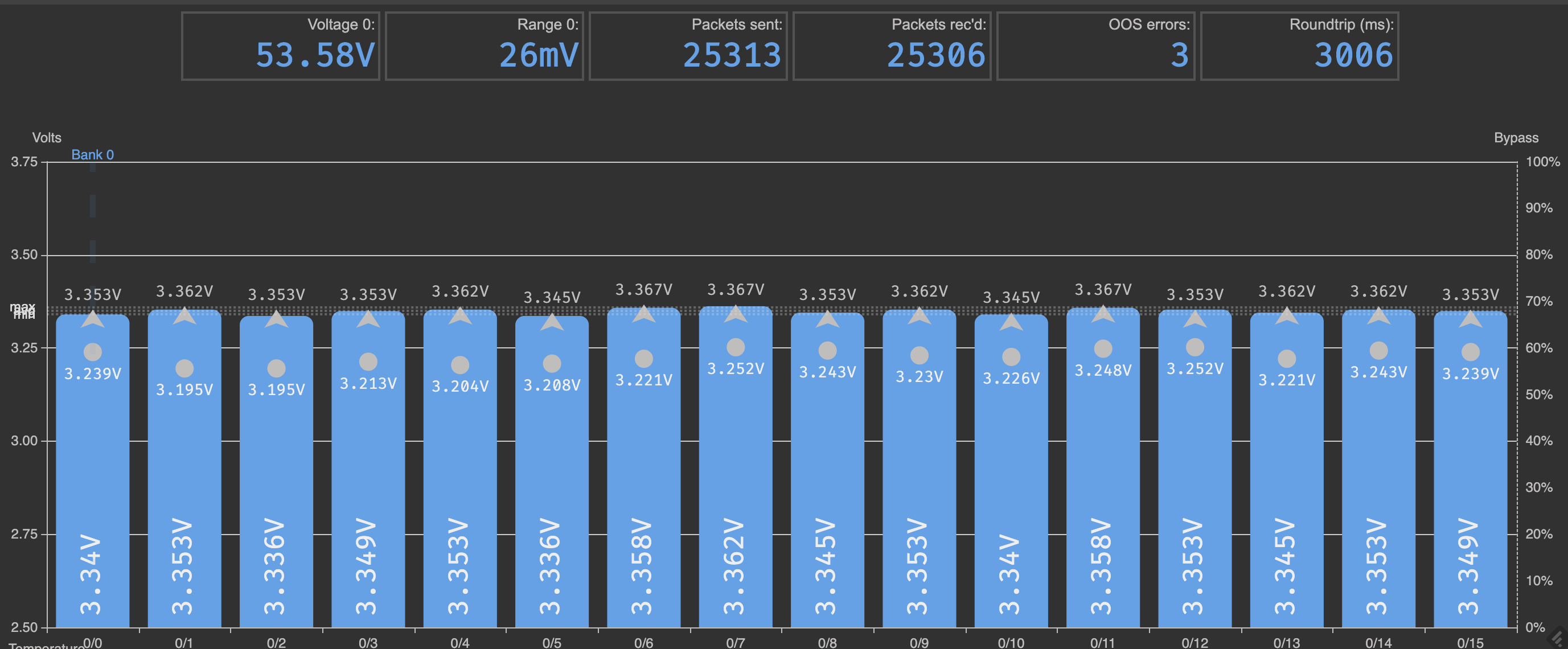
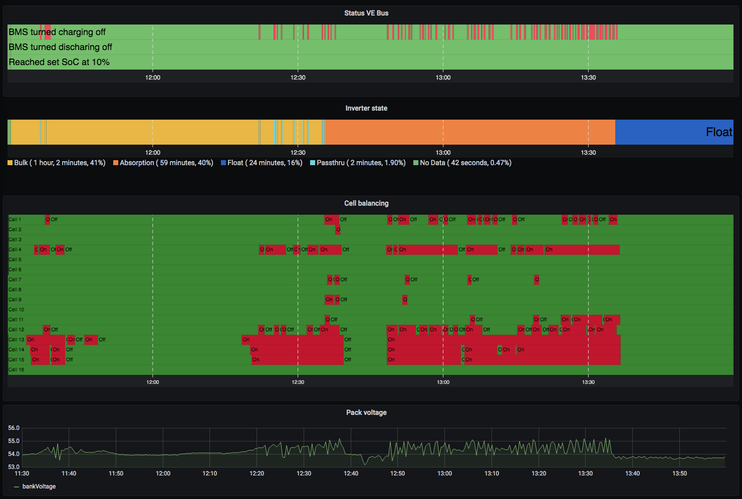
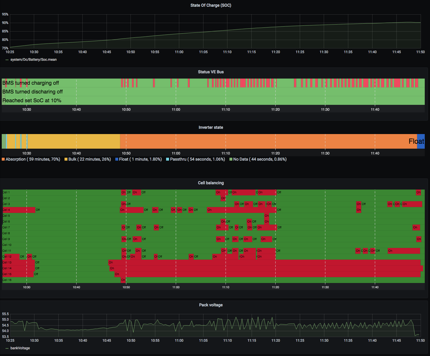
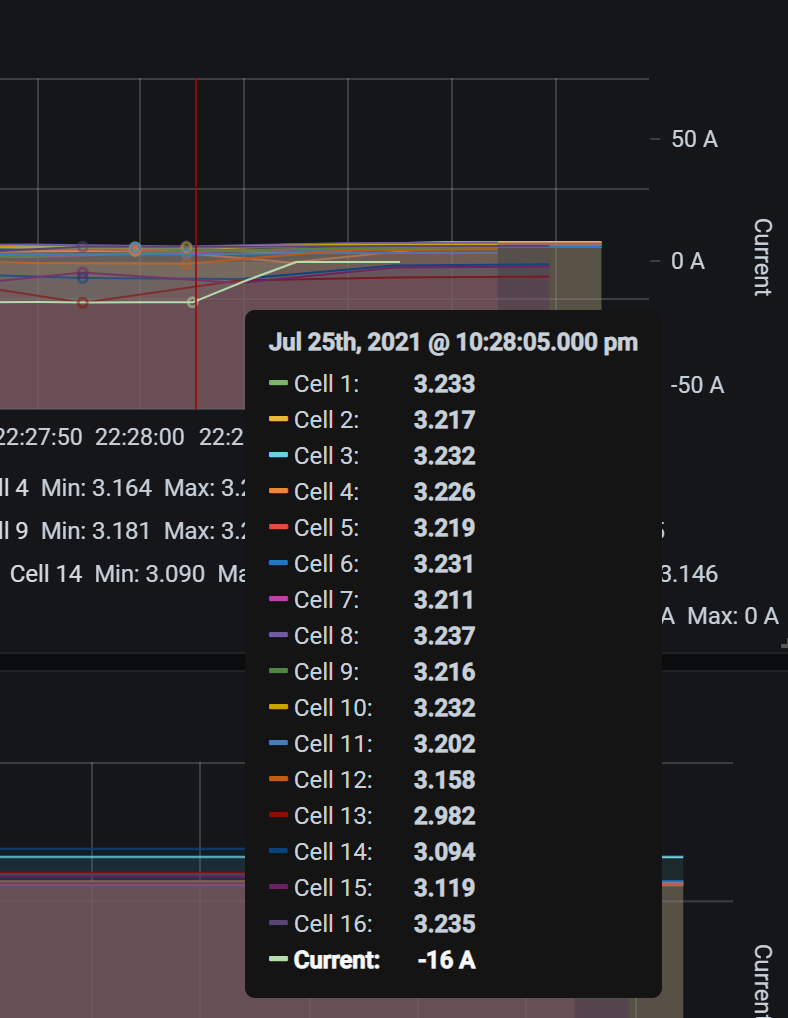
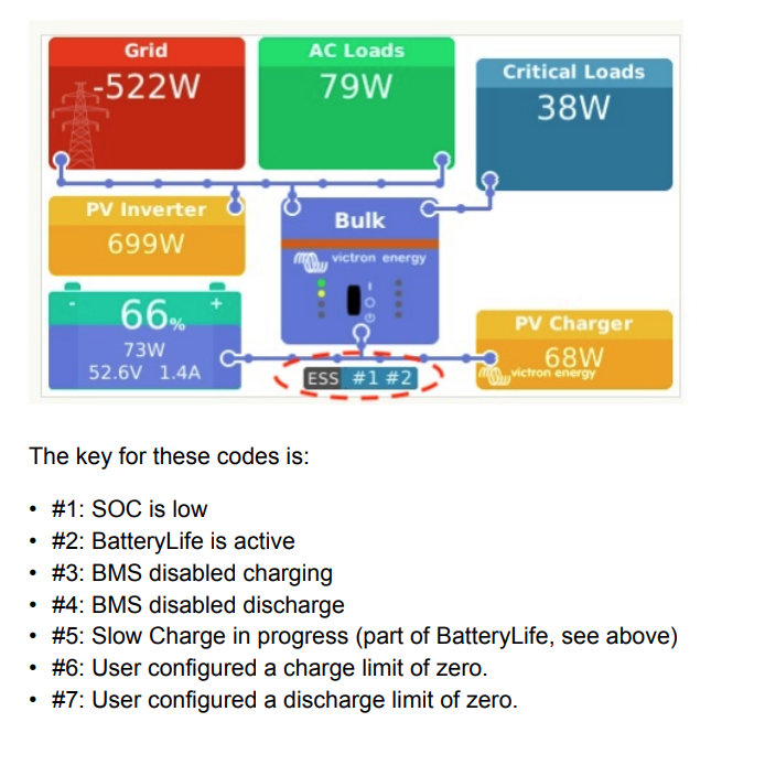
I looked at the data and i can see the pack voltage when this cell was at 3V was 51.074V
  3. Sure i can raise that to 2.8V or ?
  4. Not my intention therefore 10% SOC and low absorption.
0 Likes 0 ·
1627382513867.png (50.6 KiB)
seb71 avatar image seb71 peternielsen commented ·

I have all data but not sure what you want to see. When absorption is done what the voltage is on all cells or when ?

Cell voltages (instant values at that time) when the battery just finished charging.

-------

No cell should go under 3.0V. Ever. So you must rise all your lower limits.


Discharging regularly down to 10% SOC means pushing the battery close to its limits. Especially when you have unbalanced cells and/or not perfectly matched cells. Keep in mind that the SOC indication is only approximate. When close to empty and close to full, the cell voltage is the much better indicator of the charging state. At 2.6V the SOC of that cell is close to 0%, if not 0%.

0 Likes 0 ·
peternielsen avatar image peternielsen seb71 commented ·

So here is a day while we were not home and just when absorption was done the values of the cells were this :

1627398098400.png

and here the highest is Cell #14 so it's not always Cell 13, others can also cause issues. The SOC at that time was 84% and it got to max 94% while being in float.

So what is your suggestion ? Raise cell cut off to 3v or raise the SOC to 20% ?

0 Likes 0 ·
1627398098400.png (40.8 KiB)
seb71 avatar image seb71 peternielsen commented ·

I was thinking that cell #13 might have the lowest capacity. Based on the voltage when discharged (compared with the other cells). But you also have massive differences between cells at the top.


Raise cell cut off to 3v

For sure. This is one thing to do.

raise the SOC to 20%

Yes. Rise the Minimum SOC. Maybe to 30% for now. See what cell voltages you have just when Minimum SOC is reached and ESS stops the battery discharge. If any cell gets lower than 3.0V, you must rise the Minimum SOC further.


You have lots of settings to adjust, but first priority is to balance the cells at the top.


Start by doing this:

Turn off charger when cell voltage is
3,5V

Change this to 3.6V. I don't know why you set this to 3.5V.


Decrease the Absorption voltage to, let's say 54.4V.


Limit the charging current to 32A.


See if the balancing still occurs. If it does, let it like this until you notice an improvement (the goal is to get to the state where all cells have the same voltage at the top).

If balancing does no longer occur for any cell, rise the Absorption voltage a little, until you start to see cell balancing in action (for at least one cell).


Assuming you see an improvement in cell top balancing, then gradually rise the Absorption voltage, in small steps (after a few days in which you see no change).

0 Likes 0 ·
peternielsen avatar image peternielsen seb71 commented ·
1. I changed to 30% SOC

2. I changed the low voltage cut to 3V but but should i set the reset value to e.g when shoudl it enable discharge again ? 3,1V ?

3. Turn off charger rule is changed to 3.6V and again the reset should be ? 3,5 ?

4. I changed the absorption to 54,4 which means the balance should be a little bigger than this e.g 3,45V or exact 3,4V per cell ? Should i leave float at 53,6V?

5. I enabled DVCC and set max charge current to 32A hope this is what you wanted me to do ?

0 Likes 0 ·
Show more comments
klim8skeptic avatar image
klim8skeptic answered ·

I would be increasing the balance current.

Active balancer test.

2 |3000

Up to 8 attachments (including images) can be used with a maximum of 190.8 MiB each and 286.6 MiB total.

Leslieanne avatar image
Leslieanne answered ·

Hello Peter,
Just a few comments that may (or may not!) help.

I have an identical sized system, with 16 x Winston 160Ah cells, multiplus 2 5000 48V, dc and ac coupled solar (5kw total) grid connected with ESS. It has been running smoothly for 15 months now. I can imagine your frustration with the gremlins you are experiecning. My BMS is a Zeva, and I use the 2 signal output. It has only 75mA balancers. I don't have individual cell data logging, but can view things in real time. My settings are also very similar to your latest ones, absorb at 55.2 (=3.45v per cell), float at 53.6 (=3.35v per cell). One hour absorb. However I use 3.46v as my balance threshold, cell high volt 3.65, low volt 2.8. The bms has never yet had to intervene, except during initial testing.

If your balance threshold is the same as, or lower than, your cell absorb voltage, then unless your cells are perfectly balanced and moreover have identical internal resistances, then the balancers will kick in every time the voltage rises to anywhere near absorb voltage. The cells with higher resistance will have the highest voltage while charging, markedly so at high current, so will start to "balance" first. And the small balance current will do nothing to drop the cell voltage when 30 or 40 amps is flowing. All it will do is unbalance your pack!!! Those cells will end up at a lower state of charge, unless you absorb for so long that the charging current drops to below the balancing current, and then hold it there long enough for the balancers to undo the problems they already introduced. It will get worse with each cycle. I think you may be seeing this with your pack....the cells hitting the highest volts under charge are among the lowest at the bottom. I also don't know how robust the bms cell voltage measurements are when significant balance currents are flowing, but this could be responsible for spuriously high or low readings, which may have something to do with the overshoot in cut-off voltages???

You have probably already checked this but worth a mention anyway. Your installation looks very neat. I guess from the photos you have aluminium bus bars on the cells? Aluminium rapidly gets non-conductive surface oxidation, and any resistance at cell connections adds to the internal resistance problems above. Could be worth thoroughly going over all connections, cell to cell and bms, and use one of those special electrical antiox coatings.

So, my suggestions (feel free to ignore)...
Your cells probably differ significantly in internal resistance and/or there are resistive interconnects.
If you don't want the bms to interfere while charging, raise the cell cut-off. Short times at even 3.9v at high current may not be a concern. You might also consider lowering the maximum charge current. Or drop your absorb voltage a bit more, even at 54.4 volts your cells will charge to within a few percent of "full"....but might need to extend the absorb time to get there. And raise the balance threshold to just above the cell absorb voltage. A little bit of imbalance just does not matter. It is insignificant compared to the effect of high internal resistance with high current.

Anyway, some food for thought!
Cheers, Leslie

4 comments
2 |3000

Up to 8 attachments (including images) can be used with a maximum of 190.8 MiB each and 286.6 MiB total.

peternielsen avatar image peternielsen commented ·
@Leslieanne Thank you very much for your thorough writeup. It's nice to see somebody with same setup. I am pretty sure you are on to something here. It's also what @Seb71 is trying to explain.


I have no issue with the BMS intervening by the way it has to balance, i just don't like it stops the charging cycle EXTREMELY many times....hundreds. I am worried the mechanical relays will get destroyed and then hell breaks loose. The BMS should only be balancing and cutting charger in case of emergency.

Regarding the BMS if it measures right when it balances well there might be something here true. I think i recall somebody having issues with that, i have not tried to measure while it balances what the cell reading is on multimeter and on the BMS, i might do that.

Yes i use aluminium bus bars, i don't know if there is an issue there, all i know is that when i was doing the top balance i measured between two points that were furthest away and the voltage seemed the same as when i measured only in one side which tells me that the connections should be ok right ?

So the BMS has a turn around of 3000ms meaning it takes 3s before data from one cell reaches the controller which processes the data and turns off the charger and in these 3s the voltage can raise way to much. You see right now i have cut off at 3.5V and in this case i have seen vMax on cells at 3.6V so if i raise it to 3.6V or 3.7V i am afraid that it will raise to 3.9-4V which might damage the batteries. I don't know what to do.....hard decision.

0 Likes 0 ·
Leslieanne avatar image Leslieanne peternielsen commented ·
Hi Peter,

Yes, if you have mechanical relays, many repeated rapid on-offs are to be avoided. As you say, you want the BMS to intervene only in emergencies. Setting your cell cut-off voltage sufficiently above your equivalent cell absorb voltage is the ONLY way to avoid this with your cells as they currently behave. And a couple of seconds highish is really no problem at all. We also have a small 12v system in a caravan that uses a time-proven Australian BMS (EV Power). Cut-off voltage is factory set at 3.9V. They sell (and guarantee) battery packs with that BMS, and have done for about 10 years. So I think you can relax a little in that area!

Regarding your cell voltage measurements during top balancing, they will reveal little about resistive joints if only low current is flowing. You need to measure when lots of current flows. The voltage differentials are exactly proportional to current, the old V/I = R.

Cheers, Leslie

0 Likes 0 ·
peternielsen avatar image peternielsen Leslieanne commented ·

I have 4 things i can play with :

Setting Current value
Cell bypass (balancing voltage) 3,40V
Turn off charger when cell voltage is 3,5V
Enable charger again when cell voltage is (this is hysteresis so the BMS doesn't turn off/on very quickly the charger) 3,45V
Absorption voltage 55,2V
Float voltage 53,6V


As i showed @Seb71 some cell start to have high voltage very early because of their capacity i guess as you also state so i am unsure what the magic number is.

Yes you are right, no current was actually flowing under those measurements and it's not easy to do the measurements now with the pack assembled.

0 Likes 0 ·
Leslieanne avatar image Leslieanne peternielsen commented ·

Hi again Peter,

If your cells have been properly top balanced, then cell capacity is totally irrelevant with regard to some cells running high while charging. Your lowest capacity cell will, however, determine how low you can safely discharge the pack, as Seb71 rightly and clearly pointed out already. Your problem is likely variation of resistance between cells.

Hopefully some of this might be due to connection issues. Thoroughly cleaning and checking each and every connection might be worth the effort...just in case. But if you can get your multimeter probes under your interconnects to reach the cell terminals you could test under a high discharge. Connect up the biggest load you can. Then measure between the plus and minus of each cell, and compare to measurement between the respective lugs on top that go to the BMS for that cell. Another way to test for resistant joints would be to run a big load for some time, say 15 minutes, and simply feel for any connection getting warm.

I really suggest you increase the BMS cut-off to 3.65 or more. Leave the reconnect at 3.45. Try it and see. You will not damage your cells with brief excursions up to even 4v, but if you are concerned, drop your absorb voltage a tad as well, maybe to 54.8V. You will sacrifice negligible capacity, but will effectively decrease charging current as cells reach full. And increase your balance threshold to just above the equivalent absorb voltage. As you have it now you are effectively unbalancing your pack, and possibly leading to BMS measurement errors.

Good luck and I hope you get this sorted so you can at last enjoy your new technology!

Cheers, Leslie

0 Likes 0 ·