question

danialan avatar image
danialan asked

Smart solar throttling bulk charge

Hi,


i have Smart Solar 75/15, which appears to be throttling or reducing the charge during the bulk phase.

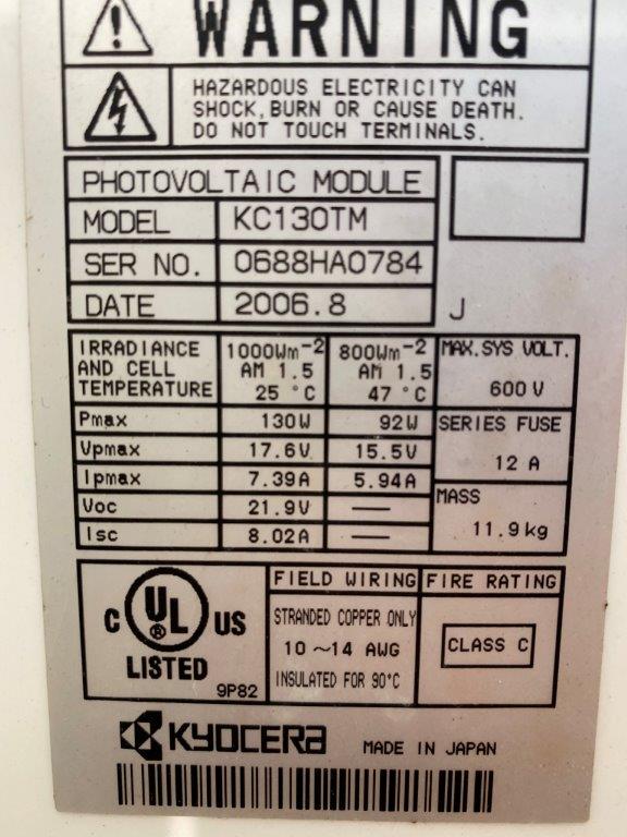
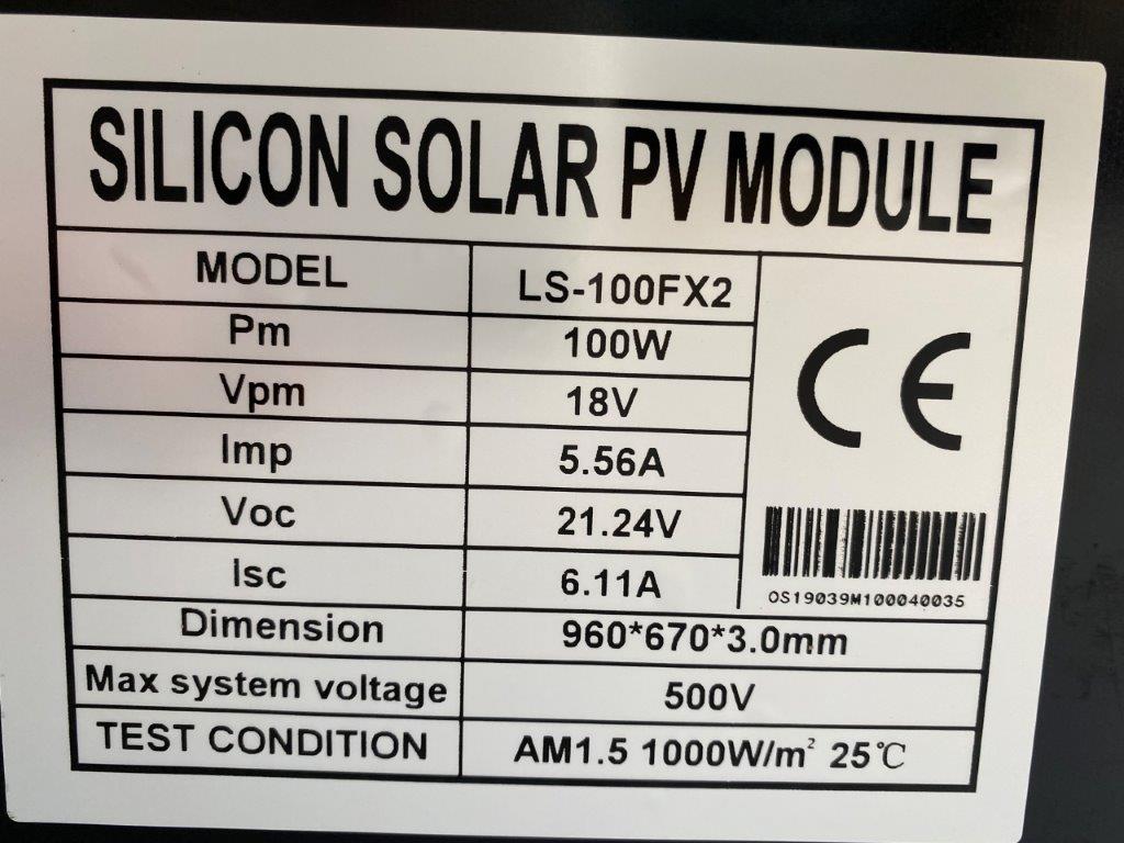
I have 2 solar panels, a 130w panel (open circuit voltage 18.2v, and short circuit current of 7.2A) and a 100W panel (open circuit voltage 18.6V, and short circuit current of 4.9A). These panels are connected in parallel. The solar controller is connected to two brand new AGM batteries 92Ah and 120Ah connected in parallel. There are no loads on the batteries.

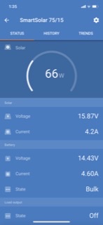
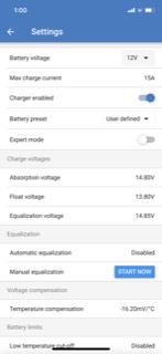
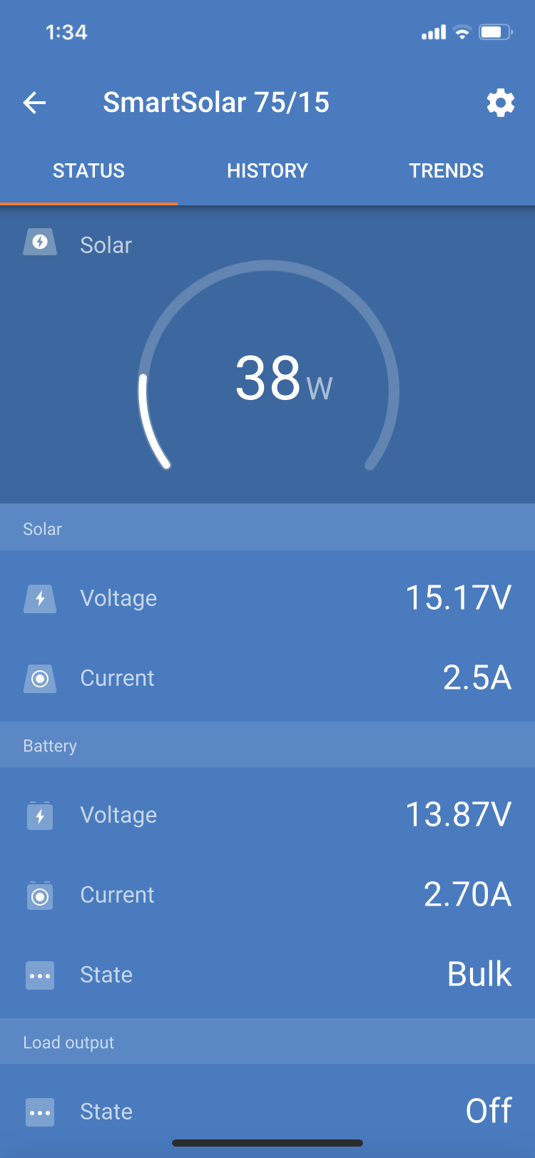
The highest output shown on my 75/15 is just 112W. The screen shot below shows just 66W with the battery at 14.43 v. This was in the middle of a sunny clear day in Australia, and just before I tested the panels with the multimeter. The Adsorption voltage is set to 14.8v. My understanding is the 75/15 should put in as much current as possible during the bulk phase. With my panels, I should see a Max of about 220W.

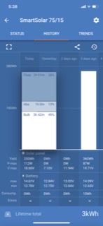
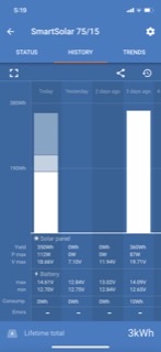
With no real load on them at the moment my batteries start at 12.7v in the morning. With the throttling behaviour of the solar controller, they seem to take ages to get up to the bulk/adsorption trigger voltage of 14.8 (which temp compensates to 14.61v). In the snip below it took 3 hours 42minutes to reach this voltage, this was in full sun from 10am!

Could someone please explain what is happening. I’m disappointed in this solar controller, as it seems to not be using the full potential of the panels, and so take ages to raise the battery voltage.


Thanks,

Alan

4b9e5464-b81f-4833-91fe-cd2f8a791d7b.png96856380-a85a-4589-b0fd-9009c86383b7.pngf1dcd8dd-6a87-45b3-9ad0-8cc2946115a5.png

MPPT ControllersMultiPlus Quattro Inverter Chargerbattery chargingcharge current limit
2 |3000

Up to 8 attachments (including images) can be used with a maximum of 190.8 MiB each and 286.6 MiB total.

4 Answers
wkirby avatar image
wkirby answered ·

In your first screenshot it shows that your PV Voltage is just a little more than 1 Volt above the battery Voltage. The controller will still operate with 1V over battery Voltage, but this might not necessarily be maximum power point of your PV array.

Also, you have two dissimilar panels in parallel which would mean that the larger panel might not get to its maximum power point either.

I'd suggest wiring your two PV panels in series. This would minimise the effect of the differences between your two panels.
Series wiring would also raise your PV Voltage up which would give the MPPT controller a larger window in which to find the maximum power point.

1 comment
2 |3000

Up to 8 attachments (including images) can be used with a maximum of 190.8 MiB each and 286.6 MiB total.

danialan avatar image danialan commented ·

Thank you for your response, I appreciate your time.

There are still a couple of things I don’t understand.

  1. As you point out the MPPT controller has reduced the 18.2v produced by the solar panels down to 15.8v. I would assume that the 75/15 controller programming has reduced the voltage to try and obtain the maximum power point for the panels. With this reduced voltage I would expect a corresponding increase in current. When tested with the multimeter, the panels produced approx 220W. 220W /15.8v = 14 Amps. Yet the current in the first screen shot (above) is only 4.2A ??? At 18v these panels produce around 12A combined. During the bulk charging phase, the 75/15 should be charging at full current. Yet it only seems to be using around a quarter of what is available from the solar panels?
  2. If I just run the 130W panel, the Solar status shows just 38W with 15.17v and 2.5A from the solar panel (screen shot below). This panel when tested with a multimeter yields approx 131W (18.2v and 7.2A). There is (overkill) heavy duty cable running from the panel to the controller and from the controller to the battery. The 75/15 is mounted 20cm from the batteries. Why is the 75/15 only getting 38W out of a 130W panel ?
  3. I will test wiring the panels in series to see what happens. But in normal use the panels are mounted, with the 130W panel on the roof and the 100W on the side of the car, so I don’t believe series wiring is a good option for me. At the end of the day the 75/15 should be able to produce good results with just one 130W panel, and be able to quickly get fully charged batteries up to the 14.6v adsorption voltage on a clear sunny day. That is not happening for me at the moment even with 220W of panels (as displayed in the first screen shot above) where it took 3 hours and 42 minutes in full sun in the middle of the day.

Thanks again for your time


img-0856.png

0 Likes 0 ·
img-0856.png (167.0 KiB)
wkirby avatar image
wkirby answered ·

How are you conducting your multimeter tests? How many multimeters do you have?
I suspect that you are performing those tests with one multimeter, conducting each test (Voc and Isc) at a time?

The Voc (open circuit Voltage) test will be fairly accurate because the multimeter is pretty much open circuit (around 11MΩ) when set up for Voltage measurements.
So for your 130W panel you measure 18.2V Voc, the current will be very close to 0A under this test. It would be 1.7μA in reality with an 11MΩ multimeter across it.
So the power being produced is 18.2 x 0.0000016 = 30μW (pretty much) not very much power.

Next test is the Isc (short circuit current). You set you multimeter up for measuring current. Swap your leads to the Amps socket and select Amps on the dial. Now your multimeter will present pretty much a short circuit to the circuit being tested
So you put your leads onto the panel wires and you short circuit it. You can measure some current there (7.2A) but if you are only using the one multimeter you are unable to measure the Voltage at this point in time. Theoretically it'll be 0V, but in reality it's probably closer to 0.5V - 1V depending upon the resistance of your multimeter when it is measuring Amps.
So now the power being produced is 1 x 7.2 = 7.2W (pretty much).

You can't simply multiply the Voc and the Isc of a panel to get the output power. This value of these two parameters varies under load even in bright sun. Above, we calculated the two extreme ends of the power curve.

Unfortunately, some panel manufacturers bloat the power rating of their panels by simply multiplying Isc by Voc and slap that on the label.
Can you tell us the manufacturer of your panels and possibly their physical dimensions? Maybe a picture of the label on the back?

2 |3000

Up to 8 attachments (including images) can be used with a maximum of 190.8 MiB each and 286.6 MiB total.

danialan avatar image
danialan answered ·

@wkirby - Thanks again for your reply.

Yes, I measured the panels exactly as you describe with one multimeter.

Photos of the two solar panel labels below. The 130 is a Kyocera glass panel, and the 100W is a new Lensun semiflexible ETFE-fibreglass panel.img-0881.jpgimg-0882.jpgI also tried connecting the panels in series. First the 130 W by itself:img-0868.jpg
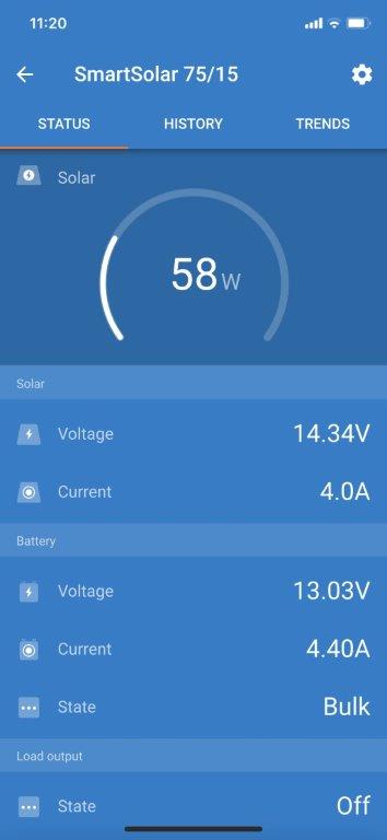
Then in the two panels in parallel img-0869.jpg
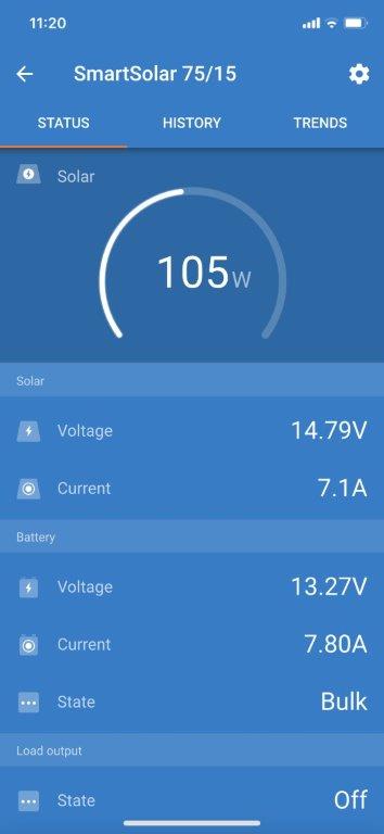
Then in series - which gave about 10% gain in battery current.img-0871.jpg
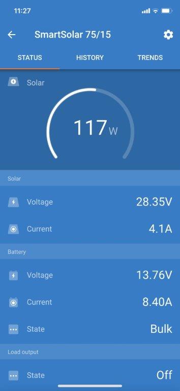
I tried this test again an hour later. The 130W by itself:
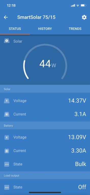
img-0872.jpg In parallelimg-0874.jpg
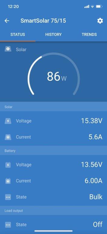
Then in Series which gave an approximate 30% increase in charging current over parallel this time?
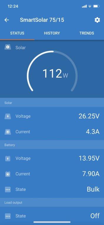
img-0875.jpg


img-0882.jpg (109.2 KiB)
img-0881.jpg (81.0 KiB)
img-0868.jpg (20.2 KiB)
img-0869.jpg (20.5 KiB)
img-0871.jpg (20.5 KiB)
img-0874.jpg (20.5 KiB)
img-0875.jpg (20.6 KiB)
img-0872.jpg (20.0 KiB)
4 comments
2 |3000

Up to 8 attachments (including images) can be used with a maximum of 190.8 MiB each and 286.6 MiB total.

wkirby avatar image wkirby ♦♦ commented ·

Those rating are believable. The Kyocera would advertise pretty accurate ratings and the other one is believable given the physical dimensions.

Another thing I forgot to ask was the temperature. What temperature is it outside and more importantly what would you estimate the cell temperature to be? Hot cells have a significant impact on the power output.

0 Likes 0 ·
Leslieanne avatar image Leslieanne wkirby ♦♦ commented ·

Hi, Yet another thing to consider is the resistance in the panel to controller wiring (including any breakers, connections, long or thin wires). If significant, and I suspect it is, given the marked improvement with series connection, then the controller will have to limit the current to hold the voltage at mpp. Just a suggestion! Cheers, Leslie

0 Likes 0 ·
danialan avatar image danialan Leslieanne commented ·

@Leslieanne the wiring is thick - 6mm core, so should have no problems. Runs are short. There are two MC4 connectors, so 4 in total. I don't trust these connectors. There must be a better option.

0 Likes 0 ·
danialan avatar image danialan wkirby ♦♦ commented ·

@wkirby I measured them yesterday in the midday sun with a IR gun - the Kyocera was 55C, the lensun 61C.

0 Likes 0 ·
danialan avatar image
danialan answered ·

Hi All,

I would still like to know more about how this controller works.

  1. During the bulk phase does the Smartsolar 75/15 charge at the max possible current right up to the adsorption voltage?
  2. Once in the adsorption stage, and a load starts drawing power bringing the voltage down, does the controller stay in adsorption or does it go back to bulk?
  3. Once in the float stage, and a load starts drawing power bringing the voltage down, does the controller stay in float or does it go back to bulk?

Thanks again,

Alan

1 comment
2 |3000

Up to 8 attachments (including images) can be used with a maximum of 190.8 MiB each and 286.6 MiB total.

klim8skeptic avatar image klim8skeptic ♦ commented ·

Have a good look at the Kyocera label you posted..... Look at the difference in voltage,,, and current,,, (able to) be produced at different light (irradiance),,, and cell temperatures...

The Kyocera KC130TM Does appear to be a 36 cell panel. Just with really bad Vmp spec for a 36 cell panel....

0 Likes 0 ·