question

scrimma avatar image
scrimma asked

100/50 to battery wire sizing?

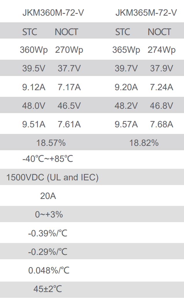
Hi everyone. I have 2x Sunpower E-20 327w solar panels that i'm going to install. The output of these panels is shown in the image below:

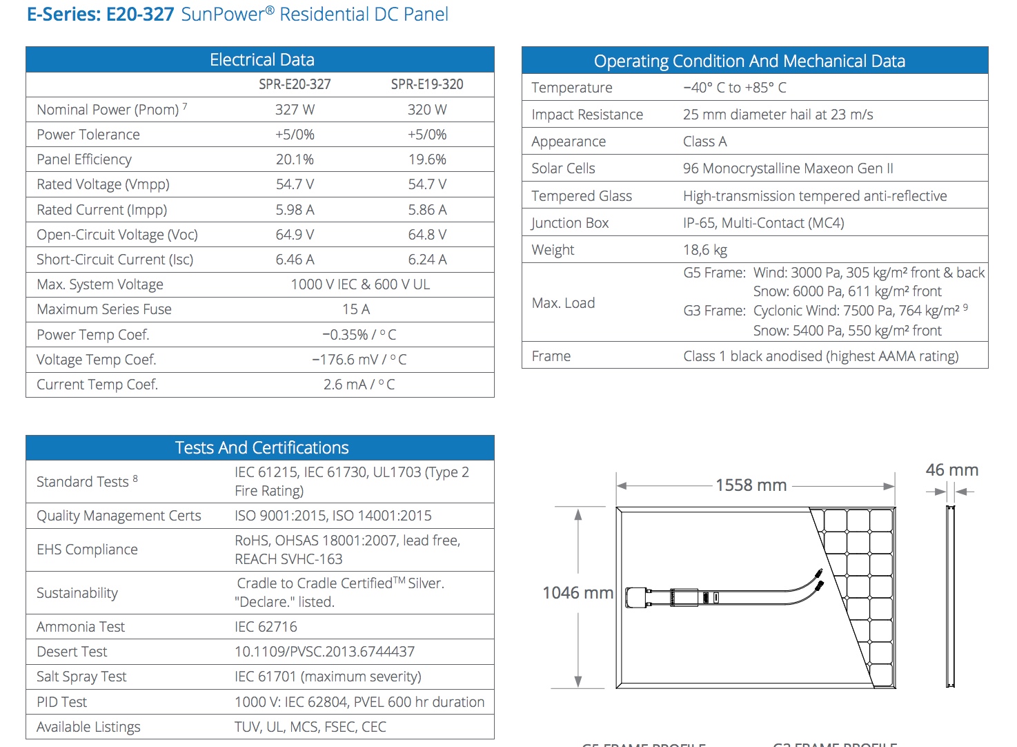
Now, my question is about wire sizing. I will use 6AWG from the panels to the Victron 100/50 smart solar controller which will be within 3' of the batteries. 6AWG is good for 37amps effective use current, so that should be more than enough for the approx 20' fun from the panels to the controller (i'm open to other suggestions on wire size if you have advice).

My biggest concern is wiring size from the controller to the batteries. The 100/50 MPPT can only accept up to 6AWG (37amp wire). From my research, that can be a problem given the panels statistics. When the MPPT uses the extra voltage to create more charging amps, the amps can spike considerably on the MPPT output side to the batteries. The panels are approx 650w together, divided by 12v = 54.17amps potentially coming out of the 100/50 MPPT to the batteries. I know there are losses here and there, but it will still be way above the max current rating of 37amps for the MPPT's max wire receptacle size of 6AWG.

Feel free to blow my limited knowledge of all this out of the water. Im new to it all but the brain cells are firing on all cylinders, but I could be completely off the rails with it all.

I apologize if this sounds a little long winded or confusing....probably because I am confused! haha.

Looking forward to any and all advice, help. Thanks in advance.


Scrimma

MPPT Controllerswiringamps
sunpower.jpeg (399.1 KiB)
2 |3000

Up to 8 attachments (including images) can be used with a maximum of 190.8 MiB each and 286.6 MiB total.

11 Answers
JohnC avatar image
JohnC answered ·

Hi Scrimma. Best to ask if confused, you're going well so far. :)

Firstly, nice panels. They'll need wiring in parallel into a 100/ mppt, and presumably use MC4 connectors, which are 4 to 6 mm2 wire suitable. (let's dodge AWG). This depends on distance of course, but it's likely you could use 6mm2 wire to the mppt safely even with a single pair. For long runs, combine to a bigger wire or run 2 pairs. The gen-u-ine solar wire is nice to work with, and a pro installer would set you sweet with 6mm2 in virtually all cases.

Mppt to batts, just use the Victron max. The distance should be short, and if the mppt is mounted right next to an inverter, even shorter wired to the inverter batt terminals, which are likely MUCH bigger wire.

If you already have a spool of 6AWG (13mm) you could carefully trim back at the ends to fit, but really..

Wherever you're getting your A ratings on wire should also cover the length, and vary to suit.

Don't overlook fusing/breakers/isolators on your wiring either. Wire terminal/tab sizing impinges on all that stuff too.


2 |3000

Up to 8 attachments (including images) can be used with a maximum of 190.8 MiB each and 286.6 MiB total.

scrimma avatar image
scrimma answered ·

Hi John! Thanks for your reply and info. There seems to be soooo many different ways of saying a size of cable it's driving me nutso. I've got multiple tabs open so i can cross reference constantly. Fun times! :)

The distance from panels to MPPT will be slightly over 7.5meters. Then from the MPPT to the battery will be approx 600mm.

That's a great idea to mount directly to the inverter. With that though, I have a regular 1000W (2000w Peak) inverter with a 240v receptacle on it. It is NOT connected to the A/C panel or anything. Basically the same setup as you would have in a vehicle. I rarely need 240v, but the odd time is handy and I got a great deal on the inverter. So, with that in mind, it would still be ok to mount directly onto those terminals? Wouldn't the inverters draw when on then not be caught by the shunt and therefore not the BMV712? Although...with that said, my inverter is wired to the shunt so it shows anything from it on the battery monitor, so am i right in assuming that if the 100/50 MPPT was connected to those same 2B&S (there's another cable size for ya!) cables, then the BMV will report all in and out without any issues?

I don't have a spool of 13mm (6AWG) yet, but was about to pull the trigger and order it. Bigger is better?! From what i've read, for 7-8m run from the panels, 13mm is the 'size up' from what would be normally required. Thoughts?


I also have another question relating to the MPPT. I want to install it next to my inverter in the STBD cabin within 500mm of one of the house batteries. Here's the catch...the shunt is right next to the other house battery 600mm away (but a 2m cable run away). Is it ok to have a short 500mm positive to the STBD battery, but run the negative to the shunt 2m away next to the other battery? Or will that do something funky with different losses in different lines or something strangely electronic like that?

The alternative is to run the MPPT into the PORT sleeping cabin and then there would be less than 1m run for both the positive and the shunt. This is definitely not preferred for aesthetics. As nice as a little blue box is to look at, the admiral would prefer to keep it out of the quarter berth and in the STBD cabin.

Thank you again for your advice on all this. Much appreciated!

2 |3000

Up to 8 attachments (including images) can be used with a maximum of 190.8 MiB each and 286.6 MiB total.

scrimma avatar image
scrimma answered ·

One other thing, do you have a little schematic that would show the appropriate circuit breakers and kill switches either side of the MPPT? In regards to circuit breakers...don't they do the same thing effectively as a kill switch? A circuit breaker can be...broken...manually. So it's effectively the on off switch? Basically, isn't a breaker effectively and can be used the same as a fuse (althouse a fuse is usually a 1 time use thing) which is the same as an isolator switch?


2 |3000

Up to 8 attachments (including images) can be used with a maximum of 190.8 MiB each and 286.6 MiB total.

Mark avatar image
Mark answered ·

Hi Scrimma,

I just had a look at some DC cable spec tables I have saved & 6AWG should be good for UP TO ~103A @ 30degC & when run as a single core. You then need to derate it as required for the cable bundle & for max temp. So x0.8 for a 2 cable bundle & x0.76 for 50degC max temp = 63A.

The next thing to calculate would then be voltage drop due to resistance & length - ideally this should be <1%, but even upto 2 or 3% loss is OK if it's not reasonable/cost effective to use larger cable. The resistance of 6AWG is ~0.0014ohm/m, so if you have a total run of ~2m (1m of pos & 1m of neg) then voltage drop is V = IxR = 50 x 0.0014 x 2 = 0.14V, 0.14/12 = 1.2% loss.

PS. The MPPT you have has a 50A output limit, regardless of the solar available.

So in summary 6AWG should be fine for the run between MPPT & batteries if the run is kept short.

However, if it's not too late I would recommend stepping up to a 150/60 MPPT so that you can wire your 2 panels in series & get away with lower current & accordingly thinner cable between the panels & MPPT.

You will also have far better performance at first light & dusk from the higher combined voltage.

Another advantage is that the 150/60 accepts upto 35mm / 2AWG cable.

Regards, Mark.

10 comments
2 |3000

Up to 8 attachments (including images) can be used with a maximum of 190.8 MiB each and 286.6 MiB total.

glenn-matthiesen avatar image glenn-matthiesen commented ·

Hi Mark, given the specs. the 100/50 should handle the panels wired in series. Yes/No?

0 Likes 0 ·
Mark avatar image Mark ♦♦ glenn-matthiesen commented ·

NO - that MPPT (100/50) has a 100V PV voltage input limit and those panels have a Voc of ~65V each (see the PV spec sheet attached to the question) so ~130V Voc for both.

It would damage the MPPT. That's why I suggested to consider a MPPT with 150V max PV voltage limit.

0 Likes 0 ·
glenn-matthiesen avatar image glenn-matthiesen Mark ♦♦ commented ·

My apologies Mark, You're absolutely correct. I took a closer look at the specs for the PV's and did the math (after I posted the question).

Having said that, the PV's I intend to use with a 100/50 have a Voc of STC 48.2V and NOCT 46.8V. Wired in series, I'm getting pretty close.

Your thoughts?

0 Likes 0 ·
Mark avatar image Mark ♦♦ glenn-matthiesen commented ·

Probably a bit too close in my opinion...

It typically depends on how cold it gets where you are in conjunction with the temperature coefficient for your panels (and the regular Voc rating).

You can calculate this or use the Victron MPPT sizing calculator with your particular PV specifications;

https://www.victronenergy.com/solar-charge-controllers

The PV voltage can exceed Voc IF you get cold temperatures in combination with good sun, or even due to temporary 'cloud edge effect' where you can get a burst of sunlight magnification as a cloud passes.

Up to you of course, but if the voltage ever goes over the MPPT max PV voltage limit, it is likely to permanently damage the MPPT (from what I understand there is no/minimal buffer).

0 Likes 0 ·
glenn-matthiesen avatar image glenn-matthiesen Mark ♦♦ commented ·

Here are the 365 PV specifications:

I appreciate and respect your opinion. The factors swaying my decision towards the 100/50 are adequate capacity (borderline) and price point. I purchased a SmartSolar 100/50 for $375 CAD whereas a 150/60 would run me $1200 CAD.

As this is an RV application, primarily summer use and the fact that I live in the Pacific Northwest and the listed Voc's are under ideal conditions, I would bet there is a safety tolerance in the 100/50 that I doubt the PV array would achieve.

I would like to install a 100VDC / 20A breaker between the PV array and the MPPT, but so far I've only been able to source a MidNite Solar 150VDC / 20A breaker.

0 Likes 0 ·
Mark avatar image Mark ♦♦ glenn-matthiesen commented ·

You have not provided the row headings for the PV specifications so I can only 'assume' what each metric is.

-0.29%/°C should be the Voc temperature co-efficient in relation the the STC Voc @ 25°C cell temperature.

So if the actual temp is 0°C, that's a -25°C delta, so -25x-0.29%= 7% HIGHER Voc. Temp corrected Voc = 48.2V x 107% = 51.7V, x2 panels = 103.4V max.

So if the actual temp is -10°C, that's a -35°C delta, so -35x-0.29%= 10% HIGHER Voc. Temp corrected Voc = 48.2V x 110% = 53.1V, x2 panels = 106.2V max.

Even though it is fairly rare for Voc to be exceeded it can and does happen from time to time, even if its only for a brief moment.

Victron have confirmed on a few occasions that the MPPT max voltage limit has no/minimal safety margin to be exceeded - up to you if you want to 'test' that. I do understand the cost reasons to try but it could cost you more in the end...

Regarding 100/50 vs 150/60 price delta, the difference that you quoted sounds a bit excessive to me, maybe have another look elsewhere.

Which ever model you buy I would recommend to buy the 'smart' model, as that allows you to directly monitor the performance, 30 day history, make any configuration updates & update firmware when new/improved versions are released with your phone (via Bluetooth).

For circuit breakers on the PV side, I have used the Noark 2P DC MBC circuit breakers (Ex9BP-N). As long as the circuit breaker switching voltage is higher than your max PV voltage then it should be capable (no need to 'match' voltage to MPPT if that's what your thinking...).

0 Likes 0 ·
glenn-matthiesen avatar image glenn-matthiesen Mark ♦♦ commented ·

My apologies Mark, here is the complete Spec. Chart:

I absolutely appreciate and respect your very correct opinion on this matter. You would be remiss in advising otherwise. I find it very challenging to locate complete and qualified information/advice on PV solar systems. You are a great resource. Thank you.

I did find a local Victron dealer who quoted me $695 for a SmartSolar 150/60. Nearly half the price on Amazon.ca, yet still a heavy hit to the budget. Now I find that a may have to install a GFPD as well. $$

So, given your formula using the NOCT Voc of 46.8 at 0°C, 46.8V x 107% = 50.076V, x2 panels = 100.152V max. Since I'm not planning any winter camping, I think I'm good.

If you'll bear with me, I have a few more questions.

The SmartSolar 100/50 manual states:

3.2 Grounding

● Battery grounding: the charger can be installed in a positive or negative grounded system. Note: apply a single ground connection (preferably close to the battery) to prevent malfunctioning of the system.

● Chassis grounding: A separate earth path for the chassis ground is permitted because it is isolated from the positive and negative terminal.

As my Multiplus is grounded to the chassis, I would ground the MPPT case to the chassis as well, yes?

● The USA National Electrical Code (NEC) requires the use of an external ground fault protection device (GFPD). These MPPT chargers do not have internal ground fault protection. The system electrical negative should be bonded through a GFPD to earth ground at one (and only one) location.

This appears to be the proper device.

● The charger must not be connected with grounded PV arrays (one ground connection only) You would still bond the PV framing to the chassis, yes?

3.3 PV configuration (also see the MPPT Excel sheet on our website)

● Provide a means to disconnect all current-carrying conductors of a photovoltaic power source from all other conductors in a building or other structure. I take this as a 150VDC / 20A breaker on the positive leg between the PV array and the MPPT and a disconnect on the negative leg between the PV array and the MPPT?

Apparently to Code, the GFPD must not be used as a disconnect. Should the GFPD be wired before or after the PV array Pos. breaker and Neg. disconnect?

● A switch, circuit breaker, or other device, either ac or dc, shall not be installed in a grounded conductor if operation of that switch, circuit breaker, or other device leaves the grounded conductor in an ungrounded state while the system remains energized. Is this in reference to an "uninterruptible" ground to chassis?

In all my research to date, this is the first time I heard of the requirement of a GFPD. Never heard of it on YouTube PV installs.

Thanks again Mark for your help!

Cheers,

Glenn


0 Likes 0 ·
Mark avatar image Mark ♦♦ glenn-matthiesen commented ·

Hi @Glenn Matthiesen, no problem your welcome.

As all this discussion is tagging onto another unrelated question, could you please create a new question for the new grounding related questions?

Then myself or another member can attempt to answer and it will be easier for others to find and track in the future.

0 Likes 0 ·
glenn-matthiesen avatar image glenn-matthiesen Mark ♦♦ commented ·

Will do!

0 Likes 0 ·
glenn-matthiesen avatar image glenn-matthiesen Mark ♦♦ commented ·

Hi Mark, reposted as

PV System Grounding and GFPD Application
0 Likes 0 ·
scrimma avatar image
scrimma answered ·

Hi mark! Good knowledge! Thank you for that.

The positive will be 1m and the negative to the shunt 2m. Think that's a problem? Alternatively I could run my mppt out wires to the back of my inverter where the battery cable connect as they are 2AWG and run to the positive and the shunt already. It would save some cable and another cable loss. Thoughts?

Thanks for clarifying the output of the mppt will only be 50amps regardless of input. I'm slowly getting all this stuff in my head. Haha.

Alas it is too late. The 100/60 would be fantastic. Getting the power in early and late would be brilliant. I havnt installed it yet, still in its packaging so I will look at upgrading if the budget allows. I feel like 2 of those sunpower panels should keep up regardless of parallel setup though. Fingers crossed.

As for wire between panels and mppt. The single one direction will be 7.5-8m. I was thinking of going with 6mm2 (squared) m4c wire and applicable connectors on the panel end for the parallel connections. Apparently good for 70A each wire. Throw in a couple y connectors and strip the mppt end and shove in and tighten...turn the lights on?! I'd love your input on all that too :)

I really appreciate the help!

2 |3000

Up to 8 attachments (including images) can be used with a maximum of 190.8 MiB each and 286.6 MiB total.

JohnC avatar image
JohnC answered ·

Yeh, I'm sorry I don't have the patience to round you up a heapa links. I'd use something like a 20A Noark double pole isolator/cb for a paired 6mm pv cable from the pv. No fuses there, an all-in-one.

Blue Seas has all manner of ANL fuses, batt isolators and other kit to see you right. It's high end, and add 'marine spec' the price doubles. But there's other stuff of similar specs that could suit too.

Keep the Admiral happy, The ~2m proximities of which you speak are nowhere near gamekilling. It just boils down to commonsense. Btw, the mppt>inverter cable thing is utilised onboard the Victron Easysolar box, so it's nothing new. An ANL style fuse inside the front cover sees to what is likely overkill protection.

@Mark, I'd normally agree, but with 12V batts there'd be little difference in perfomance between how those panels are wired.


2 |3000

Up to 8 attachments (including images) can be used with a maximum of 190.8 MiB each and 286.6 MiB total.

Mark avatar image
Mark answered ·

@JohnC - yes I agree, when I wrote that generic statement I neglected to consider that he is only running a 12v system & panels with higher than typical output voltage (64.9V open circuit). It wouldn't take much light to achieve the MPPT 'wake up' voltage of Vbatt +5V.

~3m total of 6AWG should still be OK, but the voltage drop @ full current will be a bit greater (about 0.21v lower @ the batteries). This will cause the bulk phase to finish a little early unless you add one of the options for the MPPT to measure voltage directly at the battery terminals - such as the Bluetooth 'Smart Battery Sense' unit (since you have a Smart Solar MPPT). These units are not very expensive & will also provide the MPPT with accurate & current battery temperature to use in the charge voltage calculations / correction's. Your battery will be better charged & last longer as a result.

If you want to connect the MPPT output to the inverter terminals instead that's fine, particularly if it helps out with cable routing, lengths & voltage drop between MPPT & battery.

Regarding the cable between panels & MPPT - the resistance of 6mm2 PV cable is ~ 0.0034ohm/m, so if your total cable length is 16m (8mx2) & your panel current @Impp is 5.98A x 2 panels in parallel = 11.96A, then the voltage drop would be V = I x R = 11.96 x 16 x 0.0034 = 0.65V (for a single fig-8 cable & the parallel connection at the panels). At the Vmpp voltage of 54.7V this works out to be ~1.2% loss - this is acceptable.

The fact that your particular panels are so high voltage & low current made this result possible, even with the 2 panels wired in parallel (rather than in series).

(But just incase your wondering, if you were to wire the panels in series then the voltage drop would be 1/2 of the parallel result & voltage loss % would be 1/4 of the parallel result with the same 6mm2 cable)

I also agree with the Noark 20A 2P DC MCB recommended - normally you use the short circuit current Isc = 6.46A x 2 panels = 12.92A then multiple by 1.25 if the load can be continuous & then by 1.25 again to provide a buffer & prevert false trips = ~20A.

You should also add a fuse for the inverter DC in & another for the MPPT charge out (consult the Victron manual for recommended sizes). Depending on your layout also possibly consider a fuse directly at the battery terminal or very close by (to protect for a short circuit in the wiring between the batteries & fuses downstream).

2 |3000

Up to 8 attachments (including images) can be used with a maximum of 190.8 MiB each and 286.6 MiB total.

scrimma avatar image
scrimma answered ·

Hi @Mark. I've got the panels installed and all the wiring as described previously. All cable runs are as stated or even shorter. I have all fuses etc in place. I have run into a problem now though. I have a 50a inline fuse between the mppt and the inverter connections that then runs thicker cabling straight to the positive of the battery. Everything works fantastic...until it get too sunny and produces too much power and trips the 50a inline breaker. Any ideas why? You mentioned in your previous comment to check the manual for fusing size, but I couldn't find that info on there anywhere. I got a 50a because the mppt is a 100/50. Should I go larger? It trips when it's grabbing about 420-440w from the panels and battery amps read somewhere around 33-35a and solar around 9.5-10a. Thoughts?

2 |3000

Up to 8 attachments (including images) can be used with a maximum of 190.8 MiB each and 286.6 MiB total.

Mark avatar image
Mark answered ·

Good to hear it's up & running (kind of...)

Regaring the fuse size - yes it MUST be larger than max expected current, particularly if the max current can be continuous.

The general practice is x1.25 if max load can be continuous then x1.25 again to provide a margin/buffer to prevent false trips. But as long as it's somewhere >1.25 you should be OK.

You don't want the fuse to be on the verge of melting during normal operation...

This fuse is really to protect for a short circuit occurring in/at the MPPT and then full battery bank current (Many 100's of Amps) running through your cabling.

Also your cable should technically be rated at above your fuse rating to withstand a real short circuit event.

Now if your 50A fuses are blowing at ~35A I think you may have dud fuses OR you are reading the battery monitor current (as opposed to MPPT output) and you have a load running at the same time that is drawing the oustanding current...

What type & brand of fuses are you using? I would recommend using a MEGA fuse or similar. If your using a cheap DC circuit breaker I have found them to not be very reliable.

Regarding looking in the manual for the recommended fuse size - I have just checked your manual & the manual for my larger MPPT. It's not there any more... they must have removed it in a recent update. There used to be a small table with MPPT size vs min & max recommended fuse size.

2 |3000

Up to 8 attachments (including images) can be used with a maximum of 190.8 MiB each and 286.6 MiB total.

Mark avatar image
Mark answered ·

FYI I just had another look online & found that the manual for the Blue Solar version of the 150v MPPT models still has the recommended fuse size table that I was talking about - see extract below;

You should be able to use this as a further guide.

Based on this table I would say somewhere around 60A to 70A would be the Victron fuse size recommendation for a 50A max output charge controller.

I wonder why this section is not still in the other manuals, as I think it is useful info for most...


2 |3000

Up to 8 attachments (including images) can be used with a maximum of 190.8 MiB each and 286.6 MiB total.

scrimma avatar image
scrimma answered ·

Thanks @mark! Much appreciated! I can pick up a 60a in my little town I call home so I'll give that a go. If it pops a bunch I'll grab a 70a. I did have a bunch of draw (approx 12amps) when it was popping at around 33ish. I was giving it a run around the block so to speak to get a better understanding of it all. That probably didn't help the 50a breaker popping, but it's a good thing I found out it's under sized. So, thank you very much for the help!


1 comment
2 |3000

Up to 8 attachments (including images) can be used with a maximum of 190.8 MiB each and 286.6 MiB total.

Mark avatar image Mark ♦♦ commented ·

No problem - your welcome!

0 Likes 0 ·

Related Resources

MPPT Product Page

MPPT Error codes

MPPT 150/60 up to 250/70 Manual

Victron Wiring Unlimited Book

Additional resources still need to be added for this topic