I saw this video on YouTube. And thought their design not bad and Price acceptable. So I get connected with this supplier located in China. Called SEPLOS. It's a third-party manufacturing brand that not listed on Victron website.
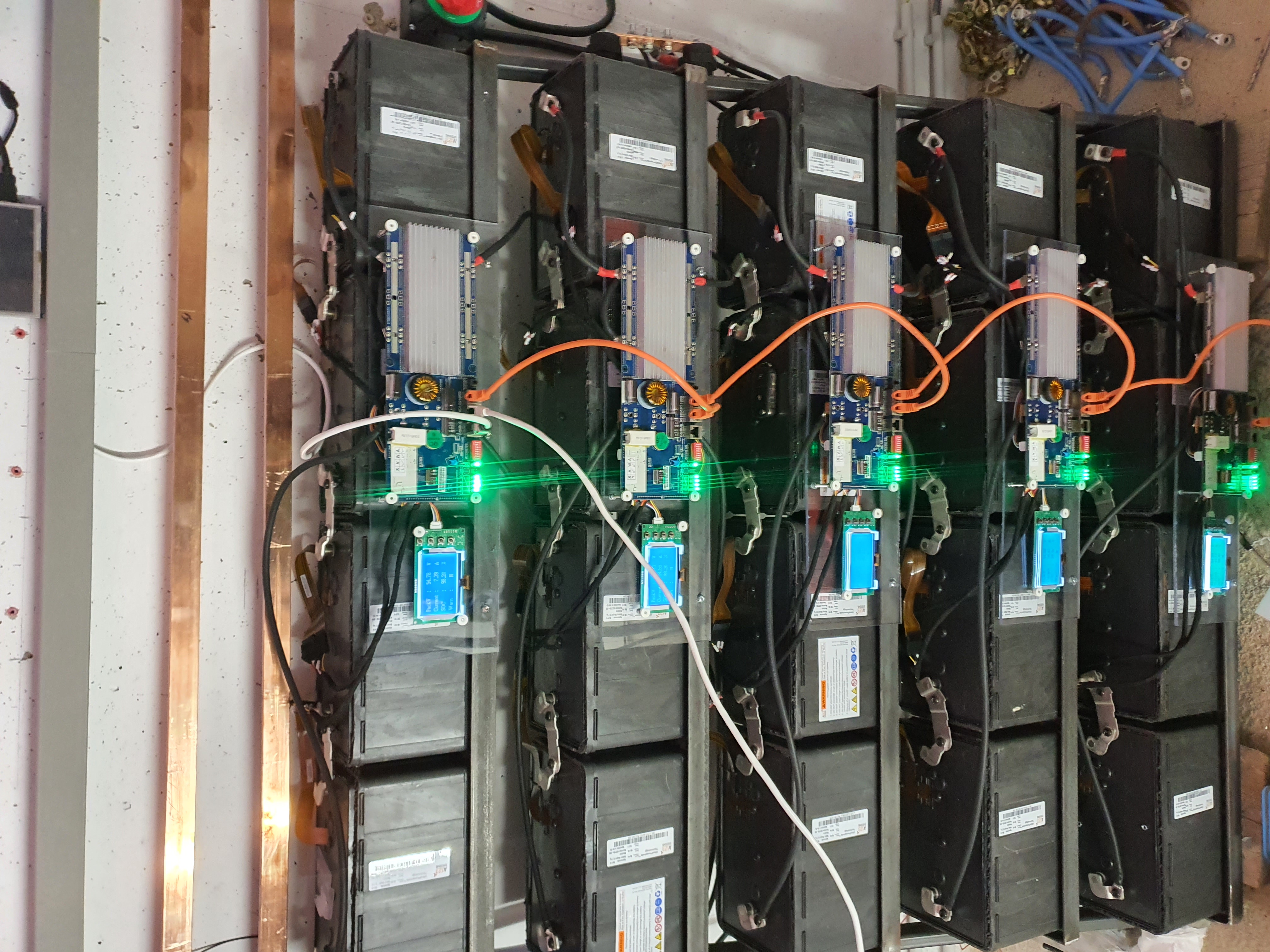
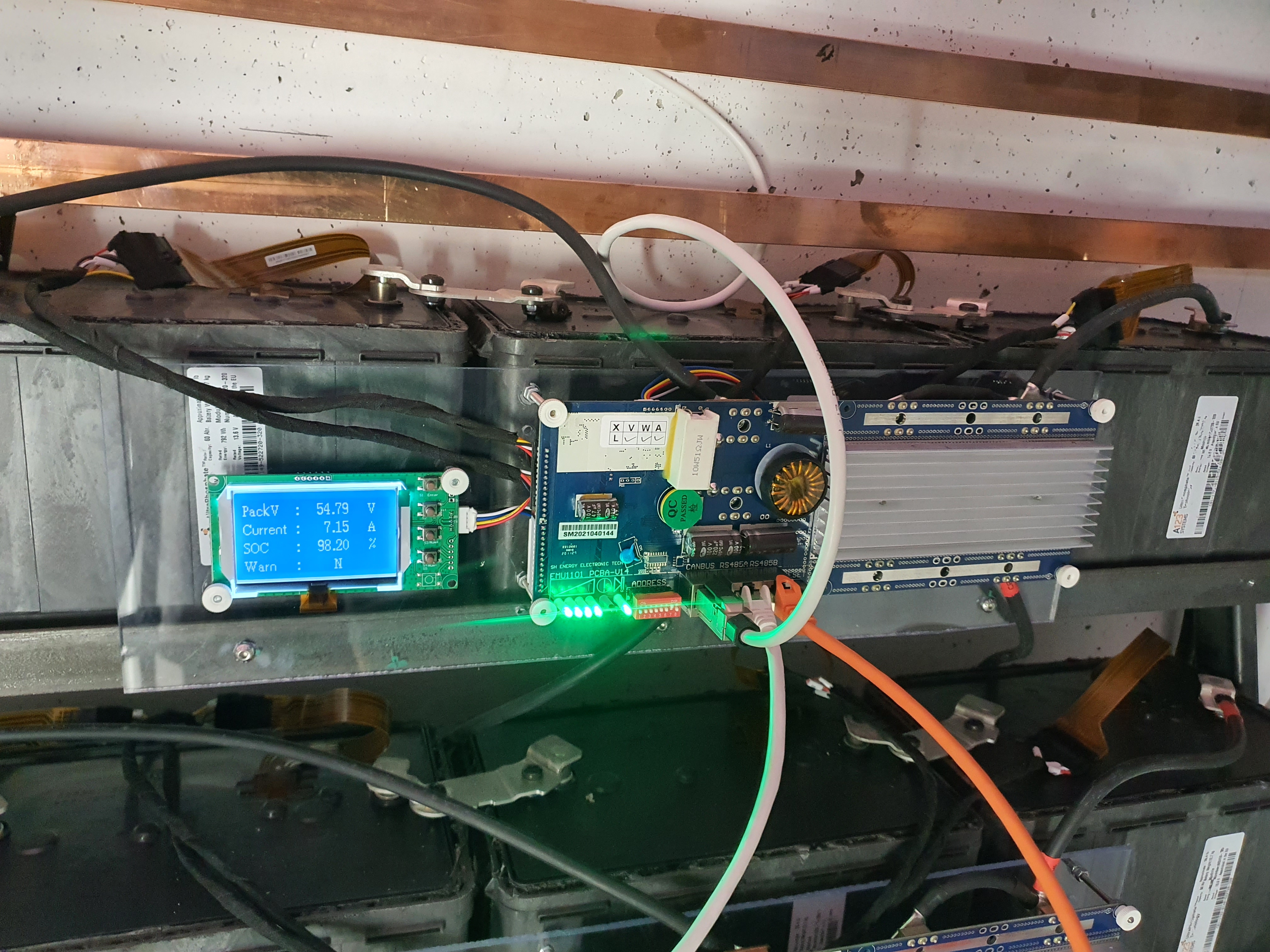
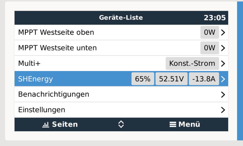
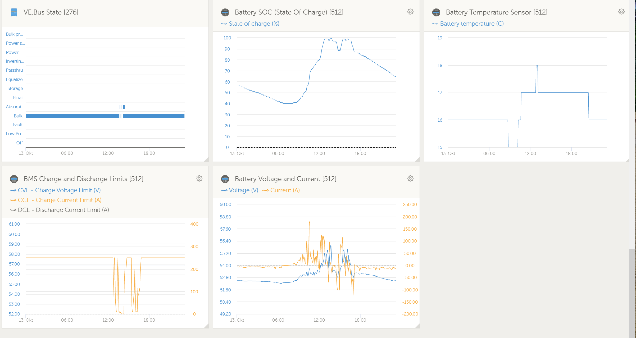
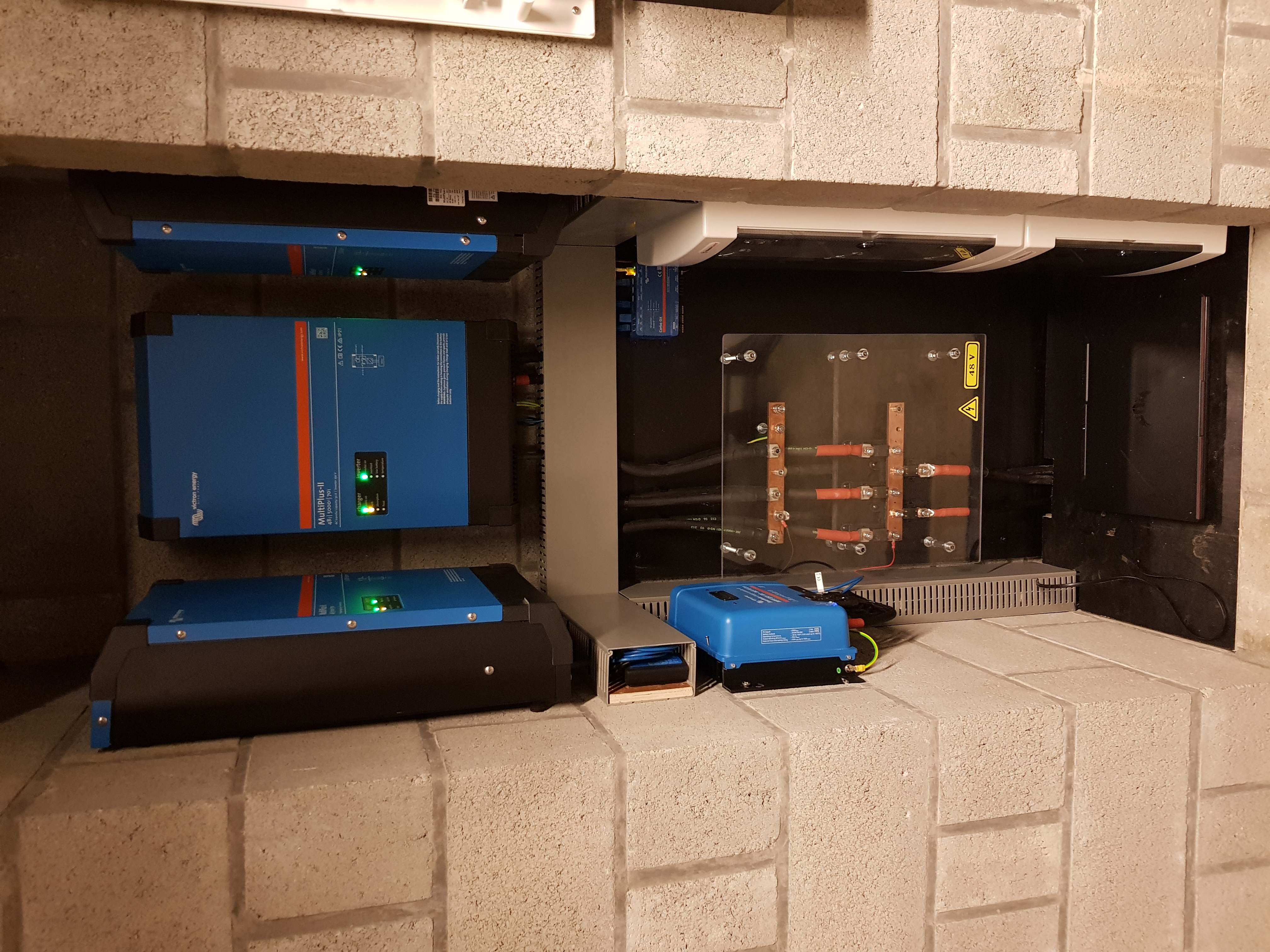
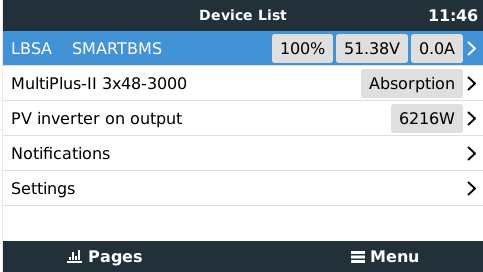
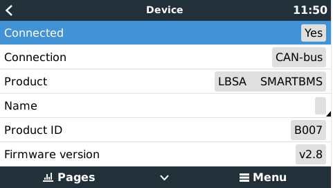
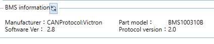
Anyway, They told me that their packs could communicate with the Victron inverter. And they send me this picture of their pack and Victron inverter. Currently, I've got the Victron Quattro 48v 5000VA. And I'd like to have a try with their PUSUNG, which is a 48v 100ah pack.

Did anyone get a battery from this company before? I would like to know your review before formal purchase.


 Hello,
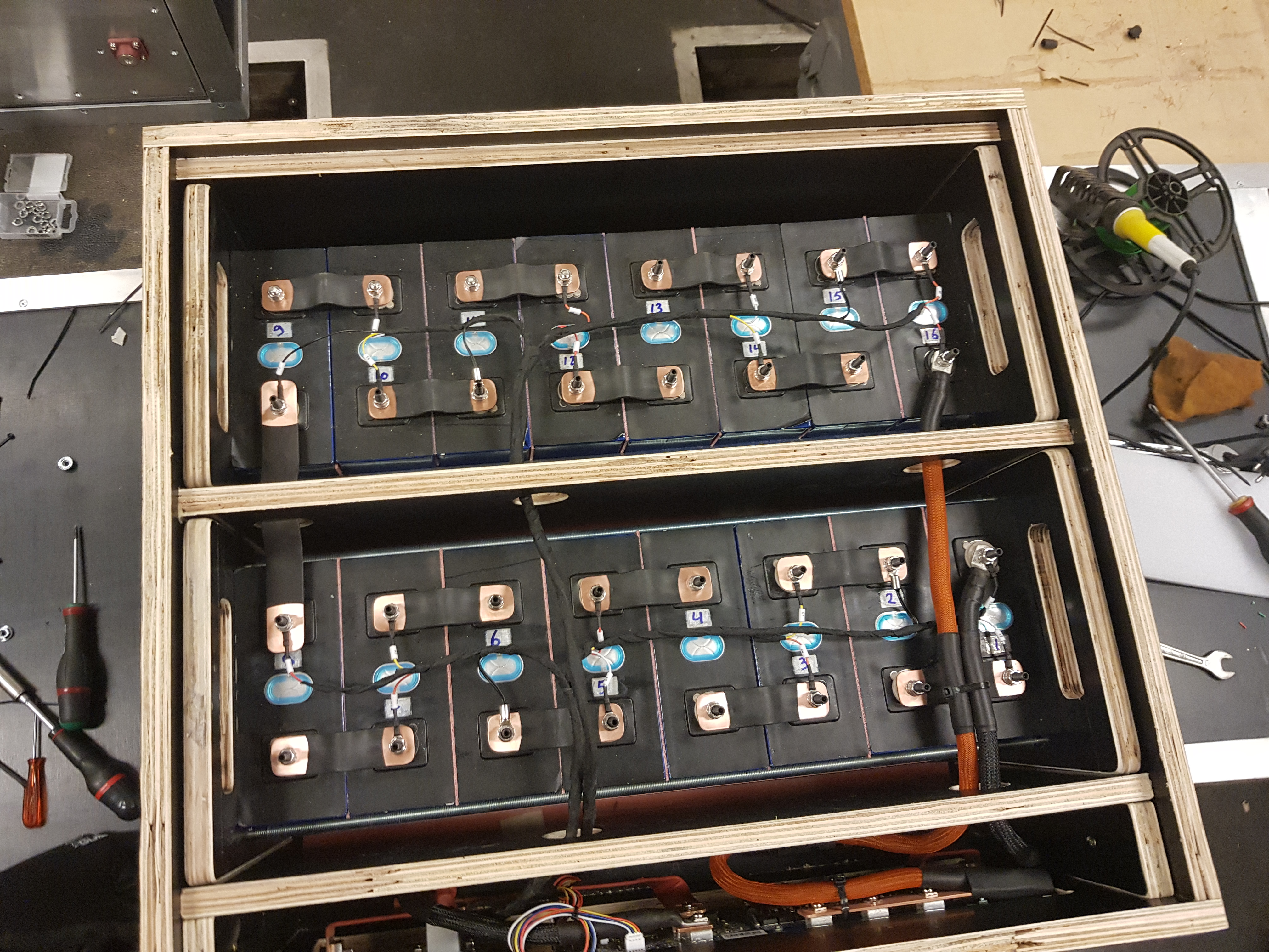