question

jmfife avatar image
jmfife asked

Mini BMS Not Charging

Hi - I have a question on Mini BMS installed in my camper van.

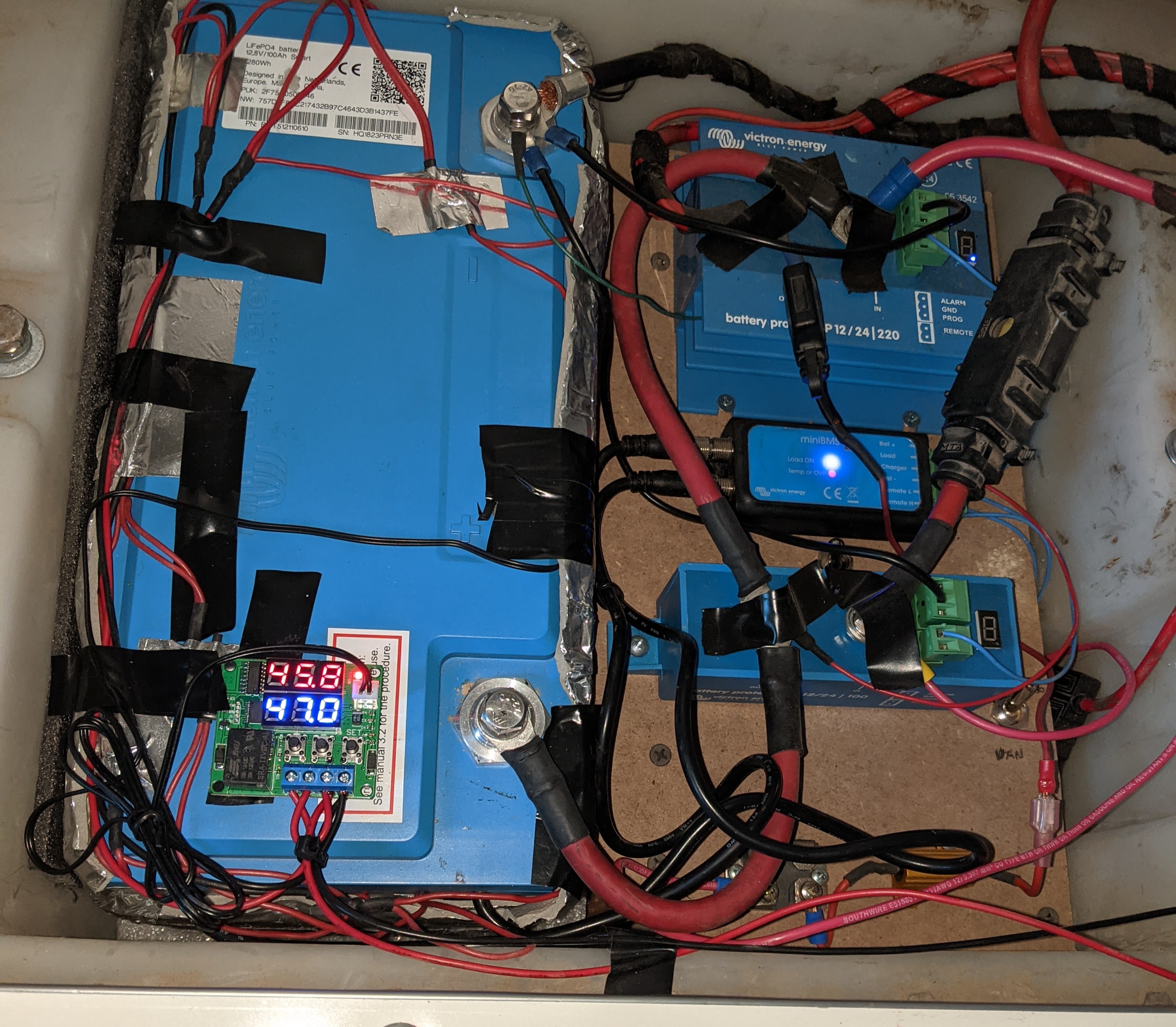
I have a 25W heater on my LiFePO4 battery to keep it warm for winter operations, and it's reading 10 degC and 13V via bluetooth. No errors or warnings shown. The 10degC is backed up by my battery heater thermostat controller / thermistor.

The battery is connected to a Mini BMS via the circular connectors, +12V, GND. The load and charge control leads are connected to the remote inputs on two separate Battery Protect devices (one for charge, and one for discharge). The system works fine (charges and discharges) during normal temperatures.

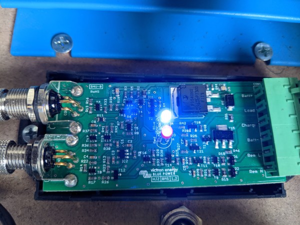
The battery temperature and voltage seem fine, yet the Mini BMS "Temp or OVP" light is illuminated and the charge output to the Battery Protect is off. The ambient air is cold (~0 degC) right now. Does the Mini BMS also sense ambient and shut down charge on cold ambient???

I am stumped at the moment.

Thanks!

pxl-20201125-155853647.jpg

Lithium Battery
6 comments
2 |3000

Up to 8 attachments (including images) can be used with a maximum of 190.8 MiB each and 286.6 MiB total.

tr001 avatar image tr001 commented ·

I came across the exact same issue about an hour ago and I'm also hoping to find help here.

Setup: Victron LiFePO4 160Ah, Mini BMS, BP65 with a solar charge controller connected.

The system works great since 6month with warmer temperatures.

My Battery currently shows a temperature of 7dC and READY FOR USE as status through VictronConnect. The BP65 status is still DISABLED BY REMOTE even though the battery has warmed up above 5dC. The Red Temp light at the Mini BMS is ON.

Good luck finding an answer jmfife and to everyone else thanks for your help!

1 Like 1 ·
jmfife avatar image jmfife tr001 commented ·

@tr001 think I confirmed there is temperature sensing in the Mini BMS that blocks charging when the Mini BMS is cold. See my update below. I want to contact Victron because this is a design flaw in my opinion.
As far as workarounds go, if we can figure out which part is the temperature sensor, there is a chance we can over-ride it by shorting it or cutting a pin.pxl-20201128-181246527b.jpg

0 Likes 0 ·
tr001 avatar image tr001 jmfife commented ·

@jmfife thanks for the update! That would be a reasonable explanation on why this happens .... I just recently installed the heating blanket with a temperature controller and before that only kept the van heated with my espar D2 which would obviously also raise the temperature at the miniBMS and not cause this issue.

I will reach out to my Victron distributor and will forward his thoughts. (I have worked with him on a few projects already and he usually gets back to me within a couple of days.)

Cheers

0 Likes 0 ·
bathnm avatar image bathnm tr001 commented ·

Does anyone know if the VE,Bus BMS does the same thing?

0 Likes 0 ·
hendrik-jan avatar image hendrik-jan bathnm commented ·

Ve.bus BMS does not have a temp sensor.

0 Likes 0 ·
jmfife avatar image jmfife hendrik-jan commented ·

Do you also know if BMS-CL-12-100 has a temp sensor? I am considering upgrading to that BMS in order to get charge current limit and pre-alarm, but don't want to have the same issue I have with Mini BMS V1.2.

0 Likes 0 ·
3 Answers
hendrik-jan avatar image
hendrik-jan answered ·

You have an Old miniBMS (V1.2) from may-2018. That one has an NTC. The new one (V2.0 with pre-alarm output) has no NTC.

Remove IC2 or short the NTC (R11) disables this.


1 comment
2 |3000

Up to 8 attachments (including images) can be used with a maximum of 190.8 MiB each and 286.6 MiB total.

hendrik-jan avatar image hendrik-jan commented ·

Remove R10 and or T6 should also work.

0 Likes 0 ·
Paul B avatar image
Paul B answered ·

Hi I hope this maybe of help you, this is what I have deduced from testing and its my interpretation of the connections and thus I may not be correct,

as Victron has not been forthcoming with supplying the technical information so far.

how to check, in the small BMS cable coming from the battery there are three pins. each pin is a loop connection and if any one loop opens then the BMS triggers the fault

One loop is if any one cell goes low voltage the loop opens

one loop is if any one cell goes High voltage then the loop opens

one loop is if any one cells goes under or over temp then the loop opens

In the wire there are 3 colors Brown Blue and Black

black I think is the temp control wire, I myself live in a temperate zone so have never really used or tested this black loop myself


2 |3000

Up to 8 attachments (including images) can be used with a maximum of 190.8 MiB each and 286.6 MiB total.

jmfife avatar image
jmfife answered ·

I have new information about this issue.

I came out this morning and my battery would not charge once again even though the reported battery cell temperature was 12 degC. The red "Temp or OVP" LED was illuminated on the Mini BMS. I opened the case of the Mini BMS and gently blew warm air on the PCB with a hot air gun. Within 2-3 seconds, the "Temp or OVP" LED went out, and charging was again possible.

So I believe the Mini BMS may also measuring ambient temperature and the logic has an OR that will not enable charging if either the battery is cold or the ambient temperature is cold.

This is the first time I have had a design issue with a Victron product.

Does anyone know how Victron can be reached about this issue?


1 comment
2 |3000

Up to 8 attachments (including images) can be used with a maximum of 190.8 MiB each and 286.6 MiB total.

Matthias Lange - DE avatar image Matthias Lange - DE ♦ commented ·

You could contact the dealer from whom you bought the BMS and he can forward it to Victron.

0 Likes 0 ·

Related Resources