question

jgd-ess avatar image
jgd-ess asked

Multiplus II and ESS Config

Hi,

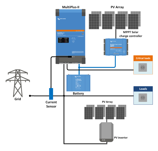
I have a Multiplus II 3000, with 150/45 MPPT, Venux GX and 11,2 Lifepo4 Battery with 3rd party BMS. (PV inverter is a Fronius IG30 without data connection to the GX).

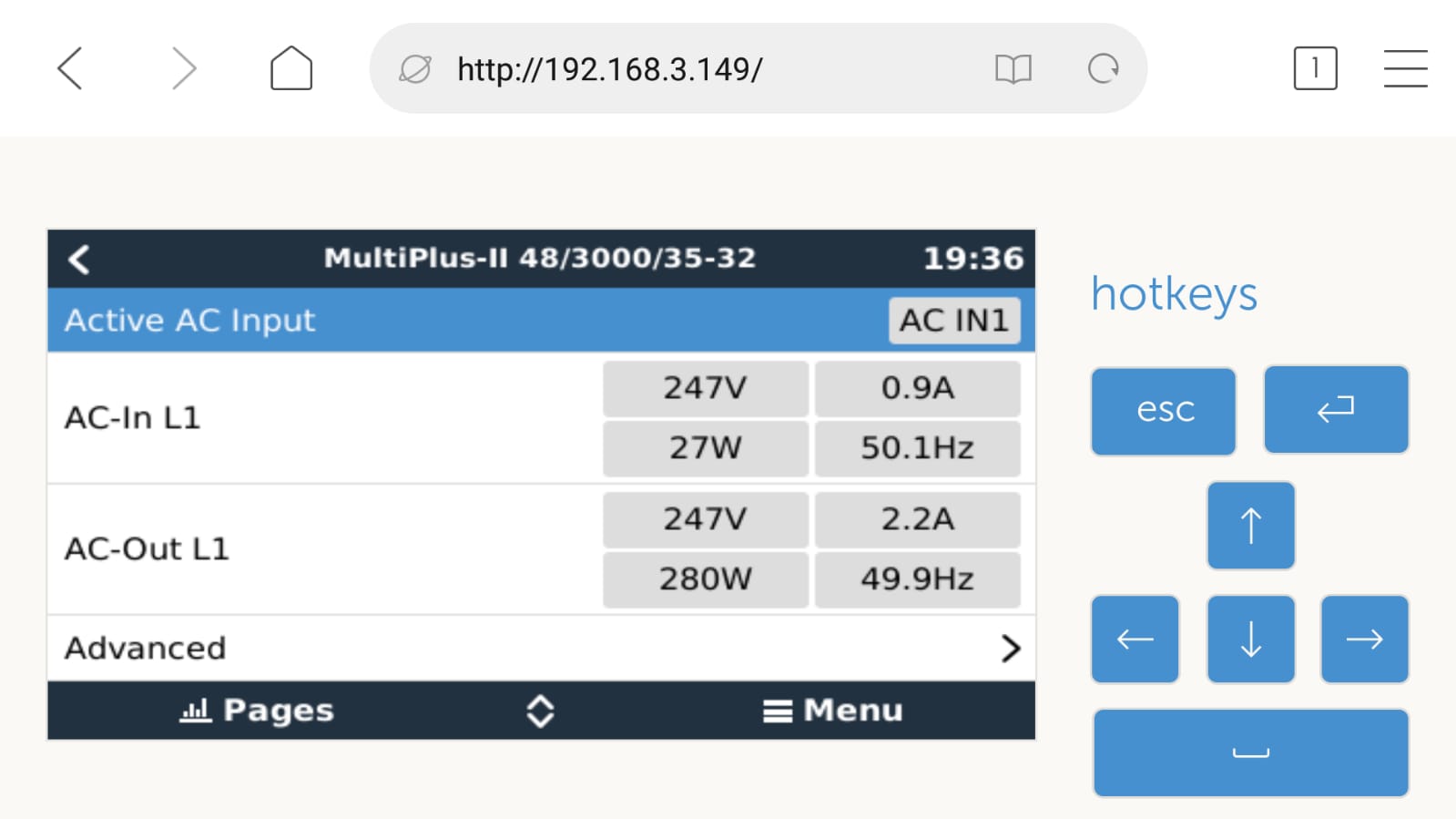
On ESS defs, with "NO grid meter installed", I get system working but the "Critical Loads" not appear:

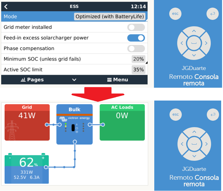
When Grid Meter Installed is select, the system dont see "any meter" and get this behavior:

Is this config, I get Critical Loads Readings, but not the AC loads, but unfortunately the system go to Passthru Mode (Stop loading and unloading the battery and becomes a museum piece).


I am truly disappointed with Victron. The first Multiplus II came out broken (over temperature error), it was replaced. The Spanish technicians after several attempts of remote configuration can not do the configuration. Last week I had to trade Venus GX because he died at once, forcing the exchange.

I ask for your help to make the installation truly functional. Suggestions?


Multiplus-IIESSEnergy Meter
scenario.png (59.4 KiB)
withoutmeter.png (93.2 KiB)
withmeterdef.png (87.7 KiB)
2 |3000

Up to 8 attachments (including images) can be used with a maximum of 190.8 MiB each and 286.6 MiB total.

2 Answers
Guy Stewart (Victron Community Manager) avatar image
Guy Stewart (Victron Community Manager) answered ·

Hello JGD,

To get all the information you would like (critical loads, non-critical loads, PV inverter production, grid import/export), the system will require an energy meter. Most likely, the best choice would be the ET340 in the Single phase dual function configuration.

The system will still work without one, but you will not get the full data picture you would like.

Selecting Grid Meter Installed, without one being installed will not work (inverter will go into passthru).

ESS systems are usually complex and best resolved by a trained local technician on the ground.

2 |3000

Up to 8 attachments (including images) can be used with a maximum of 190.8 MiB each and 286.6 MiB total.

jgd-ess avatar image
jgd-ess answered ·

Thanks @Guy Stewart (Victron Energy Staff)


Installing a meter does not seem to solve the problem. As you can see in the following image, the readings of what goes in / out of ACin and ACOut1 is well done, only the graphical representation is not being made correctly.

In any case, I have already talked to the installer partner and will soon install a current sensor to monitor the output of the inverter (PV).

Perhaps the development team can take this topic into account and in the near future this situation can be analyzed.

Another suggestion, will be to consider the clamp (CT) as a meter list in the device list.

I will wait for good news in an upcoming update.


error-datashow.jpeg (65.3 KiB)
2 |3000

Up to 8 attachments (including images) can be used with a maximum of 190.8 MiB each and 286.6 MiB total.