question

OR avatar image
OR asked

MPPT 75/15 wire terminal too small for 6mm²

Hi,

I have a MPPT 75/15 and the specs say the terminal fits a 6mm² cable. I tried that cable size and it does not fit. Without a wire end ferrule it may go in but just and it is a hassle, some strands being bend and staying out (not good), with a crimped ferrule of the correct size (it tried two types) there is no way this fits.

I have some pre-crimped cable from the solar panel (this is a kit) and the ferrule there look like a size too small and it is a 10 gauge wire which is slightly smaller than 6mm² as well. And even that barely fits.

So what am I doing wrong? Do I need to switch to 4mm² cable? It is only the 1.2m length from MPPT to battery, but 6mm² cable is what I have....


Thanks, regards,

Oliver

MPPT SmartSolarwiringterminals
1 comment
2 |3000

Up to 8 attachments (including images) can be used with a maximum of 190.8 MiB each and 286.6 MiB total.

alex-rhys-hurn avatar image alex-rhys-hurn commented ·

I'm so glad I am not the only one with this problem. So, yes they are too small. You have my sympathies.

Even a 4mm with a wire end ferrule is super snug in there.

For my PV panels I must use a 6mm cable so I am going to try to tin the cable in a nice smooth shape. Wish me luck.

But yeah, this really has me exercising all the colourful language I can think of....

Salaams,

Alex

0 Likes 0 ·
10 Answers
launacorp avatar image
launacorp answered ·

Btw:


Contacts in the MPPT are phoenix terminals and it is allowed by phoenix to use them without a ferrule because they made contact on the whole area and not at a single point like a luster terminal.

6 comments
2 |3000

Up to 8 attachments (including images) can be used with a maximum of 190.8 MiB each and 286.6 MiB total.

OR avatar image OR commented ·

Brilliant, then I will do that and squeeze it in...somehow. For now. Thanks.

0 Likes 0 ·
Matthias Lange - DE avatar image Matthias Lange - DE ♦ OR commented ·

If you have trouble getting the wires inside you maybe can try something like that:
https://www.klauke.com/de/en/insulated-pin-terminals
The yellow ones are for 4-6mm².

0 Likes 0 ·
jeroend avatar image jeroend Matthias Lange - DE ♦ commented ·

Yes I used those too, a word of caution though, when crimped on I had to make the hexagon a rectangular one again to make it fit inside.

0 Likes 0 ·
marekp avatar image marekp Matthias Lange - DE ♦ commented ·

Hmm.

The same result can be reached by cutting of 1/3 of the strands from the wire and using smaller ferrule.

But what is the point of using thick wire and make connections with this tiny connector?

Wire is cold but connection gets hot.

0 Likes 0 ·
Matthias Lange - DE avatar image Matthias Lange - DE ♦ marekp commented ·

@MarekP "Wire is cold but connection gets hot."

I don't think this will happen. You use thicker wires to reduce the power loss over long distances so the "higher" loss at this short piece of wire is nothing.
The power loss over 10mm of 4mm² cable at 12V and 15A is less than 0.01% or 0.0013V or 0.02W. The same with 6mm² is also less than 0.01% / 0.0009V / 0.013W.
So you have a 0.007W "higher" power loss with the thinner wire at the terminals.

0 Likes 0 ·
marekp avatar image marekp Matthias Lange - DE ♦ commented ·

@Matthias Lange - DE

Theory supports it, but in practice thin piece of metal, ending heavy wire, it is a risk of braking it off (or cracking) when mechanically strained by this wire hanging freely.

Add to it vibrations and we are asking for problem.

0 Likes 0 ·
Justin Cook avatar image
Justin Cook answered ·

Hi @OR, welcome to the Community!

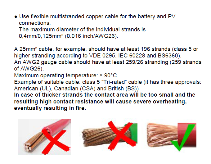
If you're using proper high-strand DC cabling (not the mid-strand THHN or anything else, see the attached photo from a Victron manual for the correct wire type) then 10AWG (6mm2) will indeed fit, but you're correct - it's tight, and can be a hassle.

Some of the THHN and other incorrect types of wire in 10AWG won't fit at all, so check your wire type first, and then, if you do have the correct type, either grit your teeth and patiently work it in there, or simply go to 12AWG.


2 |3000

Up to 8 attachments (including images) can be used with a maximum of 190.8 MiB each and 286.6 MiB total.

OR avatar image
OR answered ·

Thanks for this interesting information. According to the cable vendor, the max. diameter of a strand is 0,300mm, so it should be fine. So probably I have to thin out and use a smaller ferrule, not nice but I cannot afford to wait for another cable delivery. Then I will switch later.

Thanks.

1 comment
2 |3000

Up to 8 attachments (including images) can be used with a maximum of 190.8 MiB each and 286.6 MiB total.

sweyn avatar image sweyn commented ·
Thinning it out and then adding a smaller ferrule is a very bad idea completely misunderstanding the priorities.

Far better to just not use a ferrule.

0 Likes 0 ·
marekp avatar image
marekp answered ·

You can solder the ends of the wire to keep strands in check.

4 comments
2 |3000

Up to 8 attachments (including images) can be used with a maximum of 190.8 MiB each and 286.6 MiB total.

Please do -not- solder cables that go into any compression fitting!!!!

when using ferrules, use a square crimper to make the ferrules fit the socket.

2 Likes 2 ·
marekp avatar image marekp Daniël Boekel (Victron Energy Staff) ♦♦ commented ·

why not solder?

0 Likes 0 ·
alex-rhys-hurn avatar image alex-rhys-hurn Daniël Boekel (Victron Energy Staff) ♦♦ commented ·

Oh dear!

This is exactly what I have done, as Marek said I lightly tinned the cable end to prevent the stray wires.

Can you explain why this is a bad idea? My guess is that its now a firm round profile and therefore the surface area in contact is less than if the terminal flattened the wires out. As the snippet above from the book says its now effectively a single strand.

I have used correct sized square crimped wire end terminals, and it WONT go in there.

The cable is a proper class 5 stranded cable (albeit not a tinned marine one), and if I do it without a ferrule, then only part of the cable goes in and 1/3 to 1/5 ends up squishing out of the terminal.

As I said before, a square crimped 4mm cable will only just go in, and is in my opinion the maximum this terminal can take.

All this is made further harder by the location the MPPT controller is placed within the off road camper trailer.

So, I am now stuck.

Can anyone advise me?

Salaams,

Alex

edit: The image shared of cable types is from the Wiring Unlimited book which I did read before attempting this and choosing my cable type.

I am using a cable from Eland Cables called: 2491X / H05V-K / H07V-K Flexible Cable: Link to Cable Datasheet

I see the strand diameter on that cable is 0.31mm so is that the problem?

0 Likes 0 ·
alex-rhys-hurn avatar image alex-rhys-hurn Daniël Boekel (Victron Energy Staff) ♦♦ commented ·

Quick comment on separate note:

Thanks to Daniel Boekel and everyone at Victron for running a community forum, and for having Victron Staff contributing in there. Seems to be getting rare these days.

Alex

0 Likes 0 ·
alex-rhys-hurn avatar image
alex-rhys-hurn answered ·

Hi All,

I can confirm that it is NOT possible to professionally and correctly fit a 6mm2 cable into the PV terminals of the 75/15 MPPT Charge Controller.

Today I removed all the wiring from my panels and got underneath the MPPT where I could see properly.

There is considerable green plastic flashing on the terminal housing, and this is a push interference fit when using square crimped wire ends on a 4mm cable.

This green flashing snags on the crimp marks of the 4mm cable making inserting and removing possible but difficult.

This same flashing makes it impossible to insert a 6mm2 cable with a wire end ferrule fitted. It simply wont go past the green flashing on the terminal housing.

So, I trimmed the green flashing away, now a new problem arises.

The square crimped Legrand Brand wire end ferrule WILL NOT enter the slightly oblong hole of the green terminal block.

So removing the wire end ferrule and inserting the cable directly to the terminal is possible, but the fit to the terminal is so tight that it cannot be done without leaving some strands of wire hanging around.

So, this terminal block is at best a 4mm sq terminal block.

Sorry Victron, you have a manufacturing defect.

All the best,

Alex

PS: Yes, yes, I know I have invalidated my warranty by tampering with the device, and also possibly created a safety hazard.....

2 |3000

Up to 8 attachments (including images) can be used with a maximum of 190.8 MiB each and 286.6 MiB total.

Nick avatar image
Nick answered ·

Super disappointing to read this....come on @Victron you need to get this sorted out as it makes you look totally unprofessional.

They have lovely documentation, talk lots about correct wire sizing and fusing in their wiring handbook YET they cheap out with these terminals.

2 |3000

Up to 8 attachments (including images) can be used with a maximum of 190.8 MiB each and 286.6 MiB total.

Alistair Warburton avatar image
Alistair Warburton answered ·

At the risk of offending... And despite this being a 2 year old thread...

Why would anyone be using 6mm for 15A? I realise that for a long run you may want to increase cable size to minimise voltage drop but In those circumstances it would make sense to drop the incoming cable into a terminal box, or other device, and then take a 2.5 or a 4 from there. Provided you are in an enclosure of some sort, Tri Rated is fine and 2.5 Tri is good for 30A.

Given PV should be connected via fuses and an isolator the opportunity to reduce to 2.5 or 4 seems like a fairly straight forwards choice. My solar comes in on 25mm, and no there is not a chance that would fit into my charge controller.

Also; if a calibrated ferrule crimp tool, or even an imitation of one, is used you will find that the final form is in fact a rectangle. The round headed tools that produce a square profile result are not standard as far as I am aware. To be fair its a long time since I worked on anything that 'required' calibrated tools but I do not think the standard will have changed.

Sorry to be blunt but stuffing wires into holes is interpreted very differently around the globe and I also agree that a well designed rising, or spring, clamp terminal my actually be more secure without a ferrule. Personally I usually crimp everything up to 2.5 even if that means buying double ferrules.

Above 2.5 all bets are off, try looping a couple of crimped 10mm's in and out of a standard MCB or isolator! Sometimes, no crimp is the right crimp, especially if the tool is less than ideal.

I build and maintain Hydroelectric systems for a living and see too many horror stories to take this stuff lightly, sorry. Remember 15A at 75V is a little over 1kW which is a huge amount of heat in a small area if it all dissipates across a bad/poor termination/crimp

2 |3000

Up to 8 attachments (including images) can be used with a maximum of 190.8 MiB each and 286.6 MiB total.

Nick avatar image
Nick answered ·

Hi Alistair, still learning so apologize if this is an incorrect observation.

If we take 12V nominal voltage, 15A to the battery over a one-way distance of 2.6m which due to installation limitations could happen would result in 6.122mm2 cross sectional with a 2% allowed voltage drop. So now one is trying to stuff 6mm2 wire in....

On the PV side you're right, unlikely 6mm2 would ever be needed.

So if I understood you correctly given everything has to be fused in/out, one would come out of the MPPT75/15 with a short piece of say 4mm2 and then after the fuse scale up to 6mm2 for example for the rest of the path to the battery?

Thanks Nick

1 comment
2 |3000

Up to 8 attachments (including images) can be used with a maximum of 190.8 MiB each and 286.6 MiB total.

Alistair Warburton avatar image Alistair Warburton commented ·
Exactly yes... You would not use a wire that wouldn't adequately cope with the fault current of a CPD, Circuit Protective Device, fuse breaker whatever.

Cable specs take this into account so wire rated for 30A will withstand as much as 10 times that for the 0.05 seconds it takes an MCB to open or the 0.5 second it may take a fuse to open.

When you increase cable size to account for, and or minimise voltage, drop you don't increase the CPD value because its not about more amps in the circuit it is purely to reduce voltage drop.

Thus...

When you chunky cable comes into the enclosure, or the CPD/isolator that feeds the enclosure you can safely drop down to a cable/wire that is easier to handle within the confines of the area and limitations of device terminals.

Even for solar with the array several of hundred yard from the charge controller you wouldn't be running 6mm. 1.125kW at 75V, so 15A ish would need a 10mm to be under 4% at 400m

In reality going bigger,16mm, or even 25mm, would reduce the losses significantly.
If you did go large from a practicality point of view a 4 core 10mm, giving 20mm CSA overall, would be far easier to handle and terminate.

Good luck stuffing either of those into a 15 amp charge controller.

Good mechanical design is as important as electrical design. Proper support, bend radius, routing and appropriate enclosures for the chosen cable, or cable for the enclosures, along with ventilation weather proofing and maintenance access should all be influencing your design choices... It is about so much more than just choosing an adequate CSA and voltage rating, all be it that; that is the starting point.

(The calc is just a quick and dirty, using an online AC tool, DC would actually do slightly better but I would have to go looking up cable specs... Just an example.)

Sorry if I came across grumpy, I was, having been frustrated by other stuff all day.

I piped up anyway because this stuff matters and a one size/spec fits all is a starting point that you will want to learn your way away from.

I get everyone has to start, and I like to help where I can, but doggedly hanging on to an idea/concept and assuming the kit is bad because it will not work the way your current understanding thinks it should is a prompt to find out what you are missing, not grumble about the 'apparent' issue. But we all do it sometimes :-)

Some kit is just poor, but the bulk of it from good manufacturers is the way it is for a reason! Just not always the reason you think.

0 Likes 0 ·
jc2010 avatar image
jc2010 answered ·

There are some salient points in this thread in regards to solutions for this issue.

This however shouldn't be an issue to begin with.

When you reference a data sheet and it says that it accepts 6mm2 it is most unwelcome to discover it does not offer what is specified.

1 comment
2 |3000

Up to 8 attachments (including images) can be used with a maximum of 190.8 MiB each and 286.6 MiB total.

sweyn avatar image sweyn commented ·
But it does take 6mm2.

Just not with a ferrule.

The connector is of a type that does not require a ferrule.

0 Likes 0 ·
dennis-katinas avatar image
dennis-katinas answered ·

Hello from The Netherlands,

I was given 10mm2 cables to fit into the 75/15, obviously, it didn't work out well, although I did get them in there to some degree. 6mm2 cables did work for me.

3 comments
2 |3000

Up to 8 attachments (including images) can be used with a maximum of 190.8 MiB each and 286.6 MiB total.

Matthias Lange - DE avatar image Matthias Lange - DE ♦ commented ·

For 90Wp and max. 8A (I don't think you will ever get more) charging current you don't need 6mm² wires. 4mm² will be good.

0 Likes 0 ·
dennis-katinas avatar image dennis-katinas Matthias Lange - DE ♦ commented ·
Thank you Matthias. And what if I would add one more 90wp PV and another battery in the future? Will that still work with 4mm2?
0 Likes 0 ·
dennis-katinas avatar image dennis-katinas commented ·

So, after looking at the bill, I was given 10mm2 cables to fit into the 75/15. I have taken a 6mm2, be it with the thicker copper stands from the middle photo, but this will fit easily, at least compared to the 10mm2... I actually got them in to some degree, with strands hanging out, but by tightening the clamp the 10mm2 cables were pushed out by the pressure. So, I'll go with 6 or 4mm2

So, what has motivated my seller to give me 10mm2 cable looking at the specs of my system? To be able to add another 12ah battery and 90wp PV?

0 Likes 0 ·

Related Resources

Additional resources still need to be added for this topic

MPPT product page

VictronConnect manual

PWM or MPPT

MPPT calculator

MPPT codes