question

jabrockert avatar image
jabrockert asked

This screen is telling me my batterys are at 3.10V , and voltage error ??

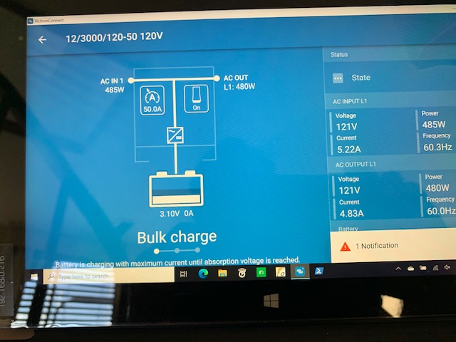
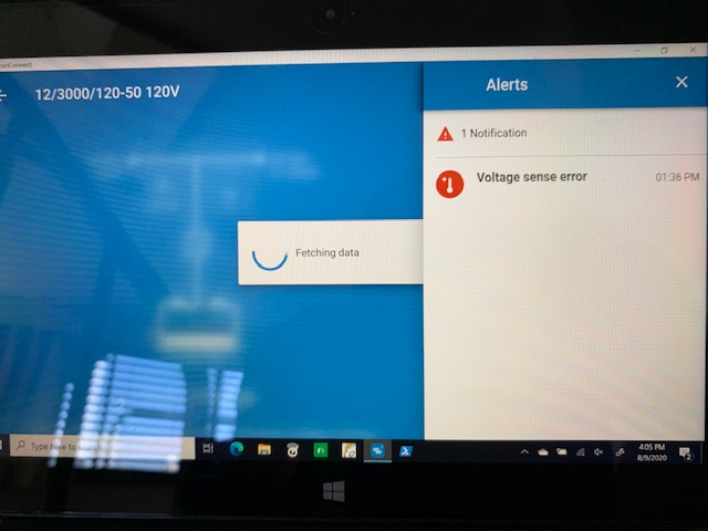
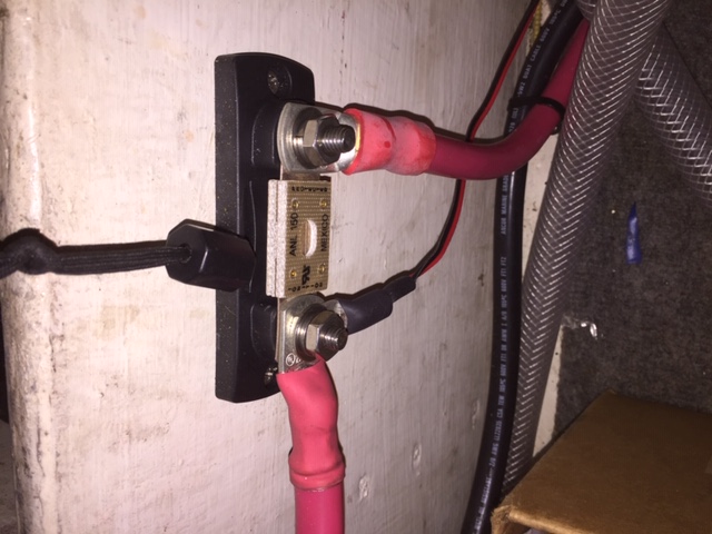
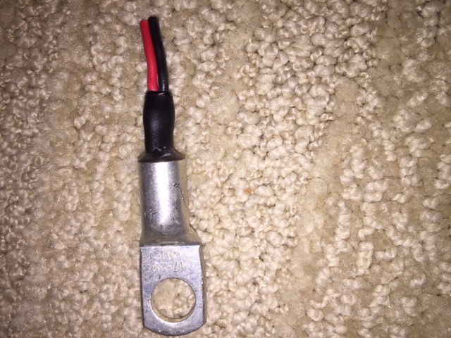
I'm got a multiplus connected up to a battery bank on my boat and I've got a over voltage error and the screen tells me my batteries are at 3.10V???, I find this hard to believe given everything is working in a normal manner. I can start the engines and run the microwave just find. I've been trying to figure this out for months. Turning things on and off, checking all connections but getting nowhere. Any ideas on a debug process.


battery charging
img-3860.jpg (77.8 KiB)
img-3861.jpg (58.6 KiB)
2 |3000

Up to 8 attachments (including images) can be used with a maximum of 190.8 MiB each and 286.6 MiB total.

4 Answers
Trina avatar image
Trina answered ·

Voltage sense error from the same day? How is your system wired up (I know might be a complex pic if boat wiring)? If everything is working fine and batteries are fine then what about last time calibrated (esp. if using a battery monitor like the bmv)? Mine did this once becauae it was sharing info via the VENetwork but I am on a simpler setup so it could be something completely different -I don't have the multiplex.

Anyway. Voltage sensor isn't working -I know, obviously, but is it separate or getting that info from a mid point or something that got disconnected or blew a fuse?

2 |3000

Up to 8 attachments (including images) can be used with a maximum of 190.8 MiB each and 286.6 MiB total.

wkirby avatar image
wkirby answered ·

As you image depicts, you have a Voltage sense error. Are the Bulk and Absorb LED's flashing at the same time?
A Voltage sense error means that there is an issue wiring from the battery terminals or busbars to the Voltage sense terminals of the Multiplus. They are sensing the 3.1V in error whereas the main battery terminals are sensing the 12V.

The battery Voltage sense terminal is the rightmost one along the row of connectors at the bottom:


1597094008108.png (28.0 KiB)
1 comment
2 |3000

Up to 8 attachments (including images) can be used with a maximum of 190.8 MiB each and 286.6 MiB total.

jabrockert avatar image jabrockert commented ·

Yes, Bulk and absorb LEDs are slashing at the same time. I'll check this wire out. Maybe it got damage while pulling it.

0 Likes 0 ·
jabrockert avatar image
jabrockert answered ·

Ok, now I’m a little embarrassed and upset with my installer. See pictures. The “sensor wire” is plugged into the correct place on the panel. However, the other end is not connected properly. I’m guessing the Red + should be connected somewhere on the battery + positive end, and the black wire connected somewhere on the battery – negative side. My installed connected both to the battery positive +. When I ask him why he said the cable/wire came that what with both ends terminated in a ring terminal that he connected to the positive + coming off the battery and he could not find anywhere in the manual where it said to cut the ring terminal off and connect each one to the + and -. Seem on page 10 section 4.4.2 it talks about “positive and negative distribution points”. I've cut the ring off and will connect up Red to + and Black to - this weekend.

You have got to watch over everything a trained technician does….ugh


img-0433.jpg (119.1 KiB)
img-0434.jpg (104.3 KiB)
img-0435.jpg (158.5 KiB)
1 comment
2 |3000

Up to 8 attachments (including images) can be used with a maximum of 190.8 MiB each and 286.6 MiB total.

wkirby avatar image wkirby ♦♦ commented ·

Oh no! That's the temperature sensor!
He was supposed to have bolted that terminal down to the negative terminal of the battery its self, then the two wires at the other end were supposed to connect into the temperature sense terminal on the left hand side of the row.
I hope you did not throw that ring terminal away. The temperature sensor is inside there. There is enough slack to join another wire onto it and then connect it to the T-Sense terminal in the MultiPlus.

0 Likes 0 ·
jabrockert avatar image
jabrockert answered ·

Voltage sensor wire problem correct and the unit is working normal.

Thanks TrinasGarden, WKirgy

2 comments
2 |3000

Up to 8 attachments (including images) can be used with a maximum of 190.8 MiB each and 286.6 MiB total.

Justin Cook avatar image Justin Cook ♦♦ commented ·

@jabrockert, glad to hear you solved the problem!

As a side note, if that ANL fuse and wiring shown comprise the circuit feeding your MultiPlus, they're pretty dramatically undersized; the MultiPlus 12/3kVA should be fed by 4/0 cable (or two lines of 2/0 for each side of the circuit) and the circuit should be protected by a 400A fuse.

As it is, as soon as you put that Multi under heavy load it's going to blow that little 150A fuse. 2/0 cable is only good to 335A outside of an engine space, though, so you definitely don't want to put a 400A fuse on the circuit as wired... but I strongly advise that you get a different installer in there, as quite a few details of these photos are NOT correct and could easily become dangerous or cause significant system instability.

0 Likes 0 ·
jabrockert avatar image jabrockert Justin Cook ♦♦ commented ·

Justin,

Thanks for the review. After seeing this install, I will not be using this installer again. I've not used the MultiPlus for much of anything and wont until these problems are corrected. I'm off looking for a new installer and will be more involved in the fixes.

Thanks again,

Joe

0 Likes 0 ·