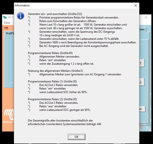
I have now programmed the Multiplus with the assistants as shown in the picture. Everything works fine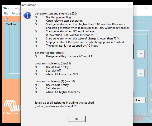 . Only one problem has arisen. If i set the "only charger" function on the digital multicontroll and shore power is connected, it will not start. The blue LED lights up "Mains on". What is missing?
asked
Multiplus 'Ignore AC Input' Assistant - How can I override it on demand?
It follows the same logic regardless if the DMC switch is ON or CHARGER ONLY, I think that's your issue.
As an ON condition overrides an OFF condition it will be hard to work around/override this.
Maybe consider to;
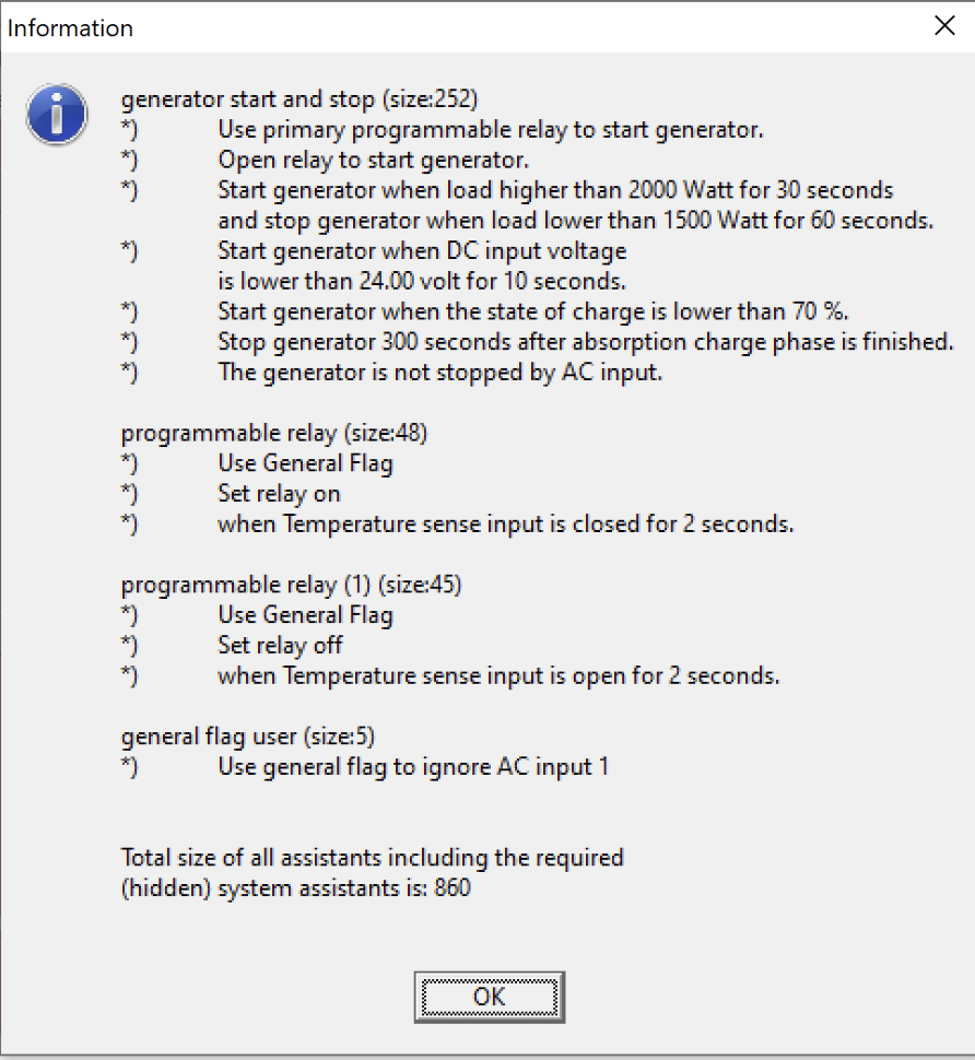
- Change the generator start/stop assistant from controlling the 'General Flag' to driving a physical 'programmable relay' in the Multiplus
- Physically wire the output of the relay in series or parallel (whatever is required, depending on the logic) with a physical override switch
- Physically wire it back into one of the Multiplus Auxiliary inputs
- Add a programmable relay assistant to use the state of that Auxiliary input to drive a 'General Flag'
- Use the 'General Flag' to 'Ignore AC Input' (same as current)
That way when you want to charge you can just flick the switch to override the logic in the generator start/stop assistant.
Also if you have a GX device, you could even use the GX device relay instead of the physical override switch and set the GX device relay control to 'manual' (allowing you to also override remotely via RemoteConsole).
Hello Mark. Thank you for the constructive suggestion. I think I have a logic problem. Now. if I can be so cheeky I want to ask you; whether you have time and desire to record it schematically?
Yes, I have a GX device (venus). Both versions would help me a lot.
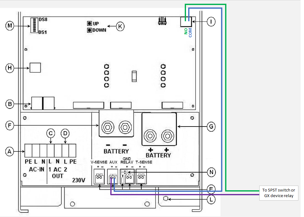
If you retain the current strategy of 'Open relay to start generator' then you would need to wire the override switch/GX device relay in series between the Multiplus 'programmable relay' and the 'auxiliary input'.
So whenever the external switch/relay is in 'open circuit' state, 'Ignore AC Input' will not be active and you will be able to charge with the Multiplus.
See schematic below:
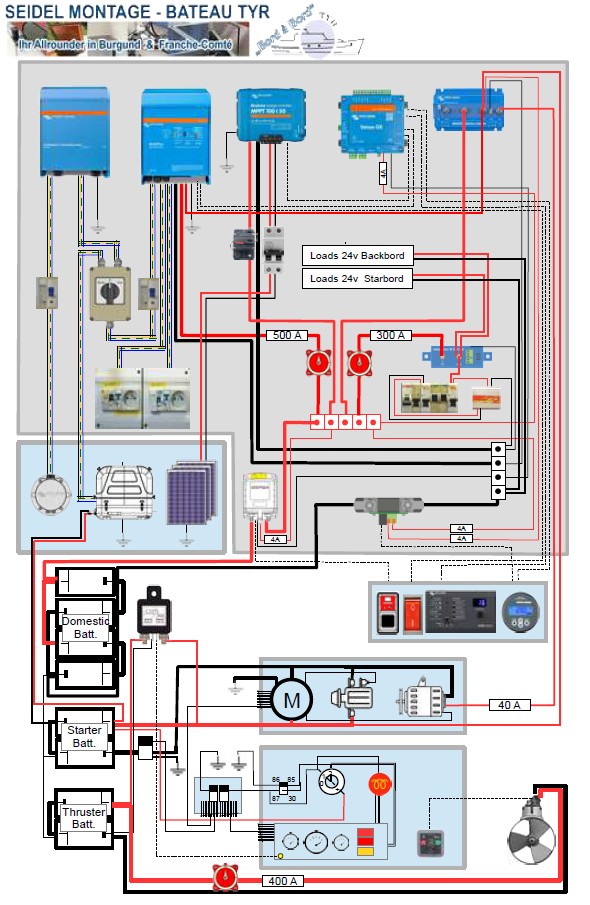
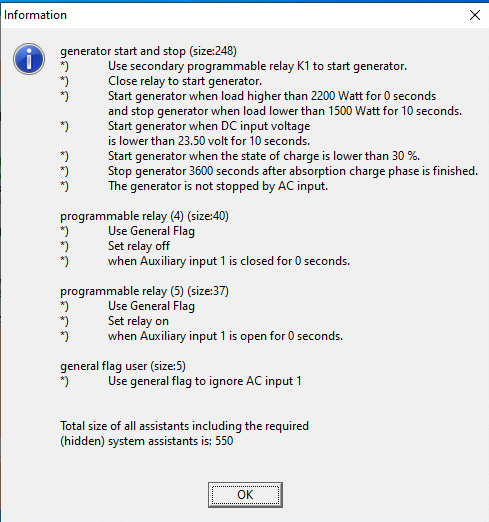
Great, that's a good solution that works. I have now installed an external switch and programmed the assistants as shown in the picture. The multiplus now uses solar power as a priority, even if shore power is available. If the battery falls to one of the programmed minimum levels, the charger switches on automatically. If there is too much solar power available, this is made available at AC output 2. A starter battery (possibly on a neighboring ship) can be properly charged with a separate charger without jeopardizing your own system and excess solar energy is not lost. With the manual switch, for example, during a longer bad weather period, without changing the programming, charging with shore power can be forced. So the system is well protected. You only pay for the really lack of energy in the port and generally "live" autonomously. Many thanks for the support here in the community! I have attached a picture of the system in question on a houseboat and a schematic of the plant. . If errors are found, please let me know! 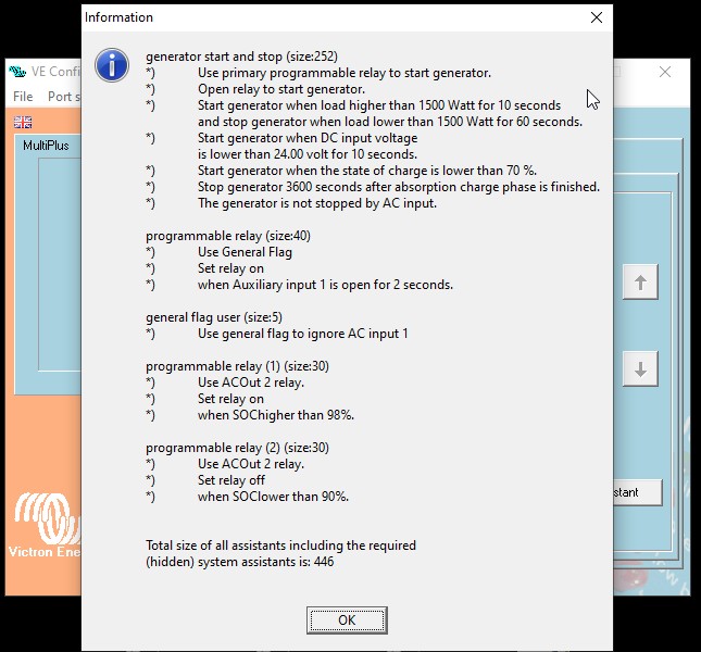

Hi @Ship Tyr,
Nice setup and I'm glad to hear that it seems to be working, but I'm a little confused as I didn't expect it to work correctly with the way you have setup your assistants...
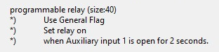
1- With the new programmable relay assistant (for the General flag) in combination with the other assistants, I think you need to 'Set relay on' when 'Aux 1 is closed' (not open) - have you run the wires to the COM & NO relay terminals?

2- I think you need a 2nd programmable relay assistant for the General Flag - to 'Set relay off' when 'Aux 1 is open'
It may just be late, but I don't know quite understand how its working properly at the moment, with your current assistants and the wiring I proposed.
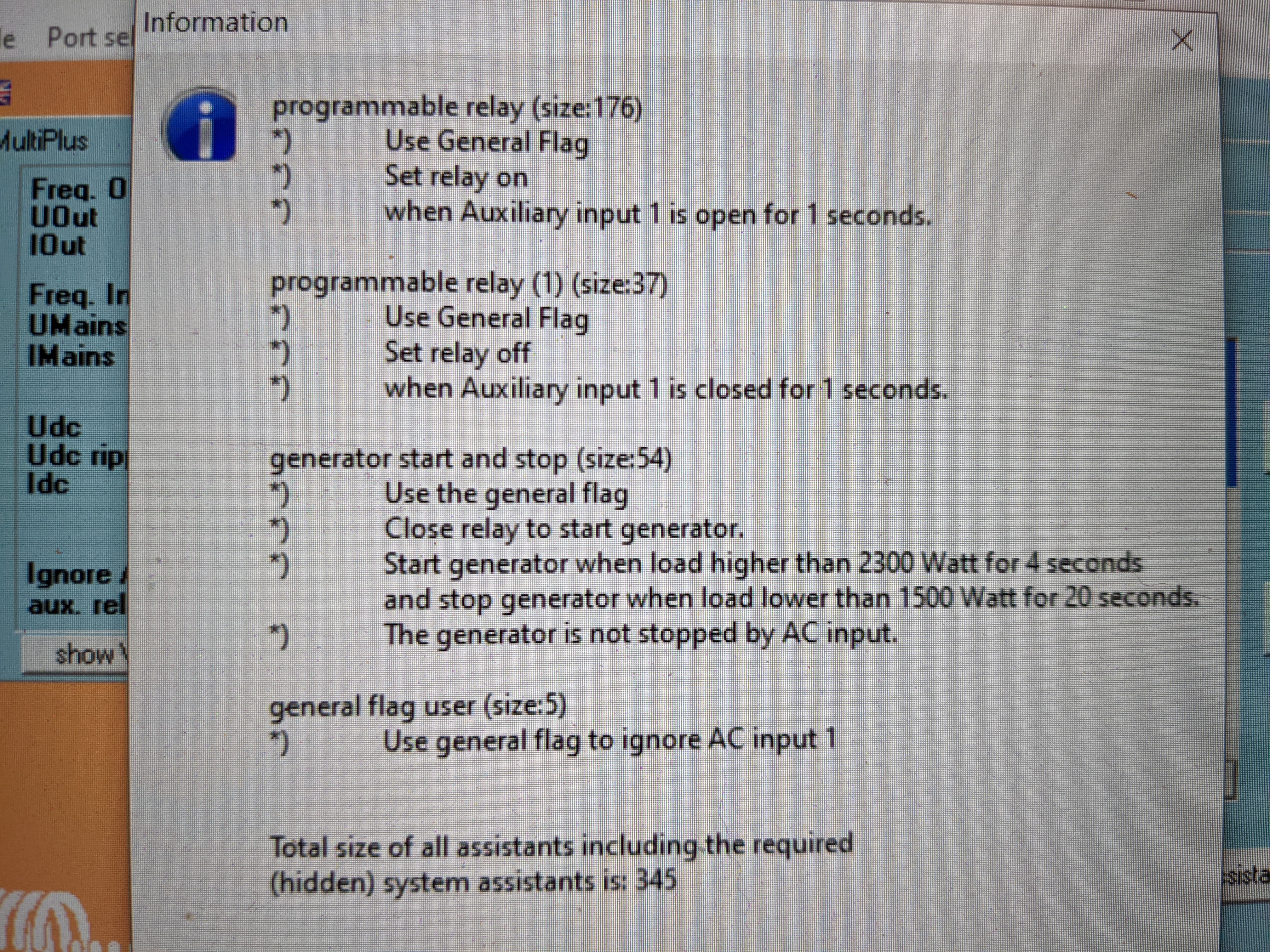
Hi Mark.It worked so far to force the load. I have not yet tried how it fit with the start / stop generator. Well, in the picture the summary. Is it so correct according to your imagination.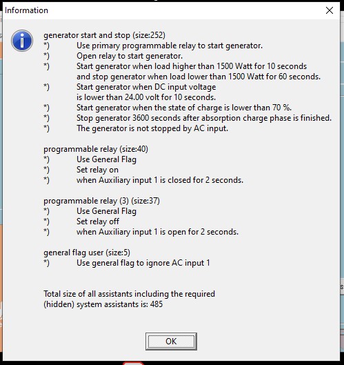
Nice, it looks correct/as I expected now.
Let me know if it's all working as expected once you have fully tested.
Trying to wrap my head around this and consolidate across the posts. Hoping you can help.
This:
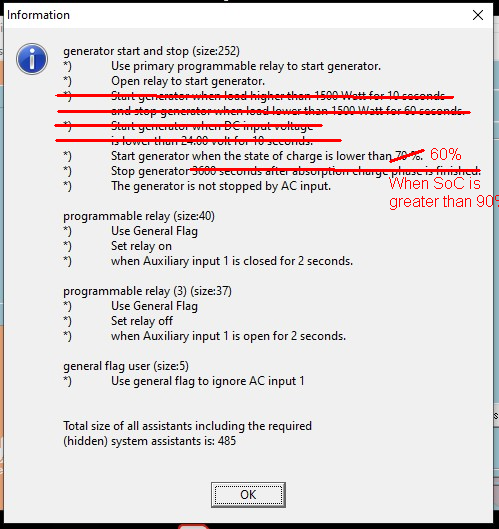
Will automatically start charging from AC input when SoC is 60% and stop when 90%.
Then, wired as follows:

This:

Will manually initiate charging when activated and stop when deactivated?
AND, with two inverters in 120/240VAC split phase configuration, do both need to be wired that way, or can I just wire the L1 inverter?
Thanks!
@snoobler
Mark may not be around, so I'll try..
What I think you'll find there is that your PR(3) will override the Gen Assistant. Try with PR(3) first in the series.
This might seem illogical, but the later ones get priority. Imagine the series being constantly read and acted upon, with the end result being the last decision made.
@JohnC
Thank you.
Trying to extrapolate the logic. Does that mean once 90% is attained, the gen stop criterion will override the switch?
And can you confirm the relay switch I circled in VRM will open/close the Cerbo relay 2?
It also appears that rather than wire to relay 1 as shown, I should have wired to relay 2 on the Cerbo.
@snoobler
Rethinking this, I'm not absolutely certain that what I'm assuming you want is correct. Like whether you want AND or OR for your 2 conditions. You can have either.
What I'd probably do personally is change out the Gen Asst for a pair of PR entries to switch via the SOC. Then you have greater flexibility with their positioning.
Then I'd just rip in and do it, keeping a close eye on the end results. That's the way you'll learn.
Sorry if this sounds rough, but if you're confident you have them in the right order there's only one way to test it. And it's easy enough to make changes if needed.
Indeed you'll need to have the correct Switch wired. But I can't answer your split-phase question, just do it if you have to.
Come back if you have strife. I like working with Assistants. And you've helped plenty others here too, so some special attention due. :)
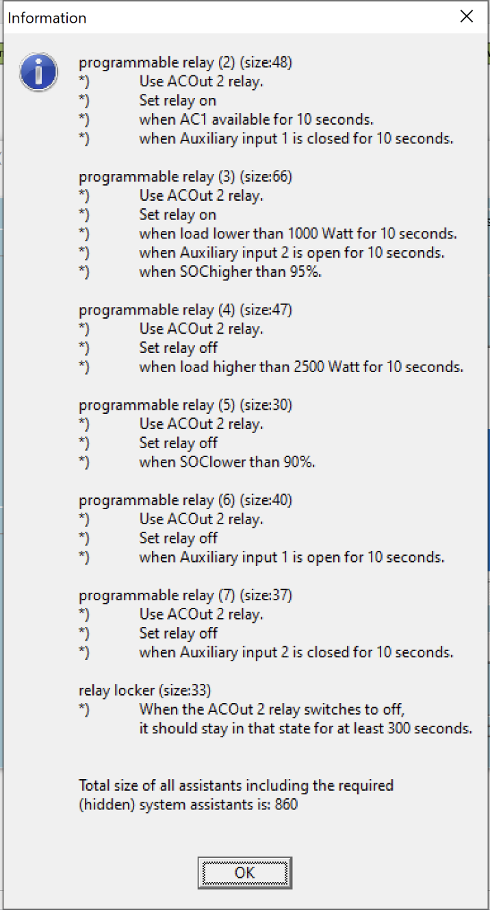
I expanded your setup here a little, by using Aux Input 1 and 2 to also control teh use of AC2 Out. My AC2 out feeds my immersion / hot water cylinder and so when the engine is on do not want the hot water tank being heated by electricity, as the engine cooling water will do that. In addition if I am not onboard the boat (aka left for prolonged periods) and hooked to the shore I do not want AC2 out used. I feed a relay to control Aux 1 when my main 12v isolator is open, so when my 12v system is active the Aux 1 is closed. I then feed Aux 2 via the engine relay, so when the engine is off the relay is open and when running it is closed.
I have the following set of assistances installed. I ran the system down so that the SOC dropped below 70%, the generator start stop kicked in and started to charge. However I would also have expected AC2 Out to be enabled due to the "Programable Relay (2)" configuration. If AC1 is available and Aux Input 2 is closed (aka my 12v system is on) then ACOut2 relay should be on. It did not switch on...
I understand that an on rule has precedence over an off rule, and there is no rule that would trigger it off, as that would need to be "Programmable Relay (6)", off if Aux input is open.
Have I missed something in my logic?
Waking this thread up...
I am configuring my system with a Multiplus-II 24/3000/70-32 and have the exact same issue as Robert here. I tried a lot of settings with assistants before finding this thread. I wonder, can this be done with the multiplus-II K1 relay? I could use the primary relay but I would rather use that for other automation. I understand that the K1 "relay" is an open collector not-real-relay, but how exactly would I wire it so it could trigger AUX1 input? I can't say that I have a full understanding of how the K1 "relay" works...
I figured it out! I am a very happy man, it is all working as I want it to work, and finally I can give something back to the community. I have learned a lot going through information here. For anybody wondering about the same thing or only how to use the K1 output to control a relay I will explain:
First, I studied the concept of "open collector outputs". One useful link here:
https://homecontrolsblog.com/2008/06/24/open-collector-outputs/
And I found a visual description of different uses:
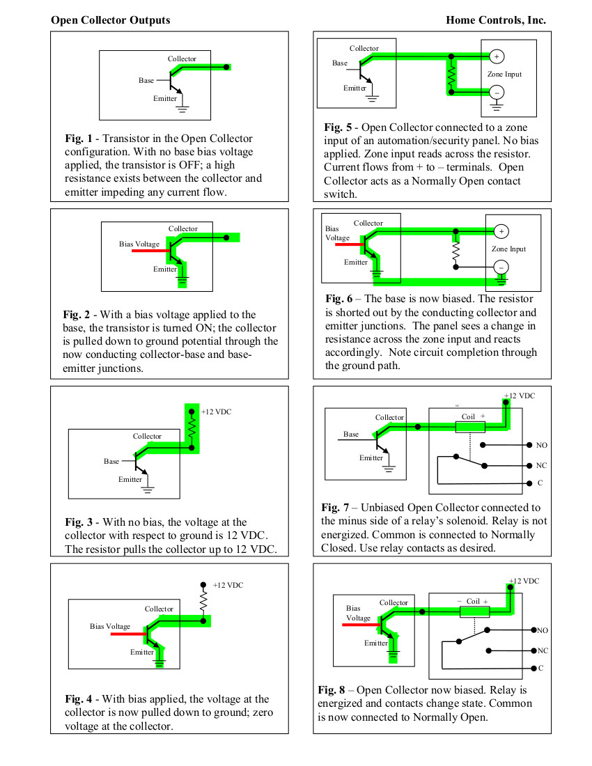
Fig. 7 and Fig. 8 is what I decided to use.
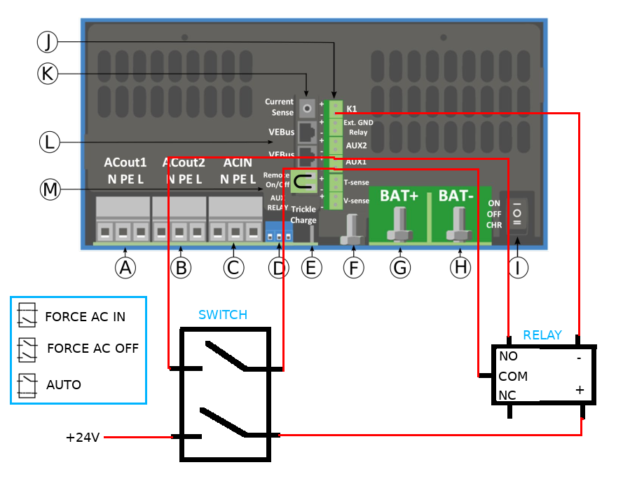
I had some small relays laying around, I tested one of them and it only pulled about 60 mA when actuated with 24v so I used that, the specs in the Multiplus-II says max 100 mA and max 70V. I connected it with a three-position switch with two isolated single switches inside. It can not actuate both switches simultaneously, so perfect for this. This is how I wired it:
And this is how I programmed the assistants:
Details are of course subject to change when I have tested it a bit more, but all is working well as far as I know now. This is wonderful, in the winter I can manually disable AC-ignore while I run the generator to charge my battery bank, this without having to re-program my multiplus-II.
In my testing I found out that the speed of switching on AC-in by high load takes about 1-2 seconds longer than if the "generator start and stop" is using the "General Flag" directly. I think it will be OK though.
Hi, that looks amazing!
I want to set up some assistants for my multiplus but it seems like I can't figure it out just right.
I want to use the AUX-in to tell the Multi to use Battery power only until a certain SoC (provided from BMV-712). While I'm using Battery power I also want to switch temporally to AC in case the draw is higher then what the Inverter can handle alone.
I managed to make always only one of the two things work but together it seems difficult. Can you help?
Ia there also a way to set up in way that it mainly uses solar and only adds what's needed from Grid or Battery?
Hi Simon, If you still need help, please let us know. Everything should be possible. Have already considered some possible solutions / explanations . But it still has to be prepared. I will contact you if necessary and after your report, as soon as possible in the next few days! BR Bob
@simon-schneider I think you will find for a domestic installation the ESS assistant will do just about all of that for you. The manual is on the Victron website.