question

elvistherv avatar image
elvistherv asked

Spiky SmartSolar MPPT 250/100 Output

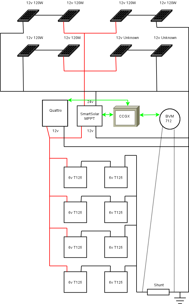
My Setup: 6x 120W 12v Panels in 3x 24v strings in parallel and 2x Unknow 12v Panels (although the same size as the 120W ones) in a single 24v string, in parallel with the other panels.

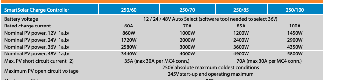
These feed into a Smart Solar 250/100.

This then connects to the rest of my system which is a. 5Kva Quattro, BMV-712 and CCGX.


All are linked via VE. Can or VE Bus and using DVCC with SVS, STS and SCS from the BMV. (I did initially join the MPPT and BMV in a VE smart network but removed that after reading the documentation).


They go into a 960Ah LA battery bank of 8x Trojan T125 6V batteries wired as a 12v bank.


So my issue is that the MPPT output seems to be incredibly spiky, with, it looks like, a lot of wasted energy.

Now I’m no expert on MPPT and I understand that the controller tries to find the “best” voltage to run the panels at for the best overall power so maybe what I am seeing is entirely normal, so based on the screenshots I’m more looking for a sense check.


I initially thought it might be shading and where I’m parked certainly there is tree shading in the morning but by mid day this is no longer an issue.

Then I thought it maybe related to it being slightly cloudy so the overal sun intensity carrying quite quickly but it’s been blue sky’s today without a cloud in the sky and it’s still spiky (the screen shoots are from today).


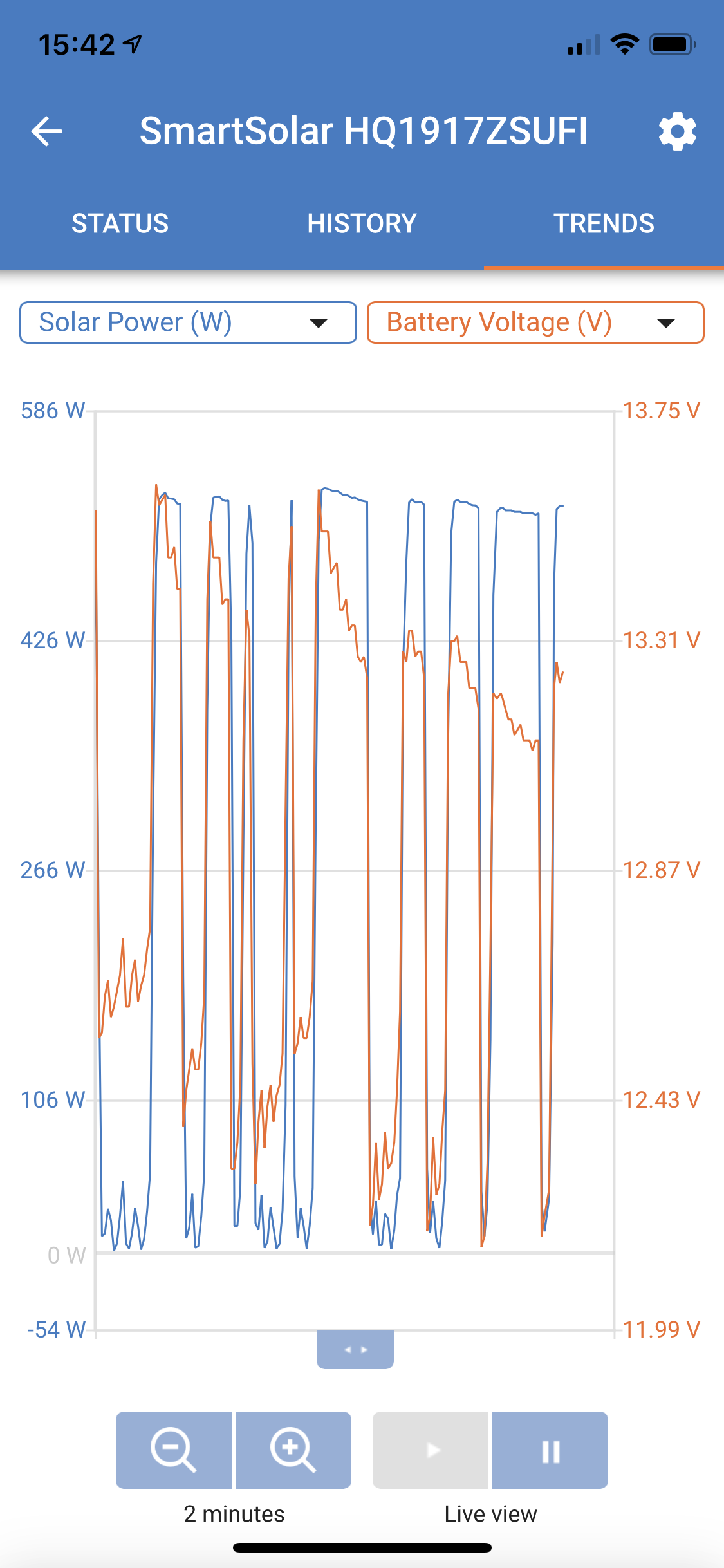
As you can see this is over a 2 minute period.


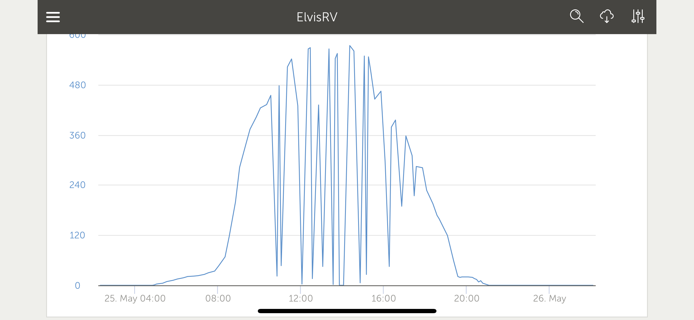
This is the days PV yield graph:

MPPT ControllersMultiPlus Quattro Inverter ChargerBMV Battery MonitorCCGX Color Control
2 |3000

Up to 8 attachments (including images) can be used with a maximum of 190.8 MiB each and 286.6 MiB total.

1 Answer
Guy Stewart (Victron Community Manager) avatar image
Guy Stewart (Victron Community Manager) answered ·

Hi @ElvisTheRV,

I think there might be an issue with your PV wiring, or solar array configuration.

Can you please provide more info:

  • A wiring diagram

  • Expected PV voltages (open circuit, and under load)

  • Measured PV voltages (open circuit, and under load)

  • Reported by the MPPT PV voltages (open circuit, and under load)

Some other installation photos of the rest of the system would also be appreciated and might help.

There is also some good information to help in Wiring Unlimited, in the Solar Section 4.10 on page 41.

Regards, Guy

10 comments
2 |3000

Up to 8 attachments (including images) can be used with a maximum of 190.8 MiB each and 286.6 MiB total.

elvistherv avatar image elvistherv commented ·

Wiring Diagram, as far as I can tell pretty standard setup:


Expected open circuit voltage would be 24v max

V max reported over the last 5 days is between 23.68 and 24.93, reading in VictronConnect broadly follows the measured voltage at the PV terminals on the controller.

Battery voltage at the terminals on the controller are approx. .9V higher than the voltage on the BVM (and match the voltage reported in VictronConnect for the MPPT so I guess SVS is working).


Cables from the PV array and to the battery are running at about 28 degrees C currently, ambient is somewhere around 25-26 currently.


The "unknown" panels were what was originally installed by a PO, the 120W I had installed, they are however approximately the same physical size as each other.

0 Likes 0 ·
rv-solar.png (37.6 KiB)
Guy Stewart (Victron Community Manager) avatar image Guy Stewart (Victron Community Manager) ♦♦ elvistherv commented ·

Hi @ElvisTheRV,

That PV Panel voltage is not getting high enough.

A single 12V panel usually has 36 cells in it. In the Victron range, for example the open circuit voltage (Voc) for a single 12V panel is between 22.6V and 23.7V.

A 24V panel, or two 12V panels in series would produce about 45V Voc.

Something needs to be checked with the panel wiring, or the panels themselves.

It's possible they have less than 36 cells, and if they do, you will need to increase the number of them in the string, probably from 2 to 4.

If they are 36 cell (12V) panels there is a wiring issue and they are not all connected as shown in the diagram.

PV Negative Linked to ground

There also appears to be an extra and unnecessary connection between the negative side of the PV and the negative side of the Battery output from the MPPT linked to ground. This could also be causing the issue you are seeing. Victron MPPTs cannot be functionally earthed like this.

This is described in page 6 of the product manual :

Section - 3.2 Grounding

  • Battery grounding: the charger can be installed in a positive or negative grounded system.

  • The charger must not be connected with grounded PV arrays. (one ground connection only)

  • The plus and minus of the PV array should not be grounded. Ground the frame of the PV panels to reduce the impact of lightning.

0 Likes 0 ·
elvistherv avatar image elvistherv Guy Stewart (Victron Community Manager) ♦♦ commented ·

OK I went and double checked and the erroneous connection between the negatives of the panels and battery doesn’t exist that is just a mistake on the diagram.

Second I double checked with the installer (and went in the roof to check too) and all 8 panels are in parallel.


Thirdly I disconnected the panel from the controller and double checked the open circuit voltage: approx. 23v

0 Likes 0 ·
Guy Stewart (Victron Community Manager) avatar image Guy Stewart (Victron Community Manager) ♦♦ elvistherv commented ·

Hi @ElvisTheRV,

If all 8 panels are in parallel, then they do not match the system diagram.

The diagram shows 4 parallel pairs of 2 panels in series.

You will need to rewire you panels so that they match the diagram.

That is why you are seeing the low voltage.

0 Likes 0 ·
elvistherv avatar image elvistherv Guy Stewart (Victron Community Manager) ♦♦ commented ·
Are you saying the SmartSolar doesn’t work with 8 panels in parallel?

I

0 Likes 0 ·
ben avatar image ben ♦ elvistherv commented ·

He's saying that eight 12V panels in parallel delivers 12V nominal to your charger. And that is too low.

0 Likes 0 ·
elvistherv avatar image elvistherv ben ♦ commented ·

According to the specs it should work with 12V nominal PV system?


0 Likes 0 ·
Guy Stewart (Victron Community Manager) avatar image Guy Stewart (Victron Community Manager) ♦♦ elvistherv commented ·

It can work, but a PV voltage that is too low can also cause problems. In your case, there is a problem and things are not working properly. So that would be the first thing that I would troubleshoot.

I have seen it before. When the panels get hot during the middle of the day, their voltage drops, also the battery voltage rises. Also the current increases, which further increases the voltage drop. This is further exacerbated if there is a mix of panels used, or if the panels are not new and some of the panels are older than others. Panel voltage also decreases over time.

Once the voltage drops below a certain point, The MPPT needs even more voltage to start up again +5V minimum from the battery voltage, and it does for a while, but then the cycle repeats.

The next step in the troubleshooting process is to wire the panels as you have them drawn in your diagram.

Raise the panel side voltage by wiring the panels in series pairs, and then see if the problem is solved.

0 Likes 0 ·
elvistherv avatar image elvistherv Guy Stewart (Victron Community Manager) ♦♦ commented ·

So is a 23v Open Circuit voltage a problem?

0 Likes 0 ·
Guy Stewart (Victron Community Manager) avatar image Guy Stewart (Victron Community Manager) ♦♦ elvistherv commented ·

23V open circuit is not the problem, that is the maximum panel voltage.

I think the problem might be the minimum panel voltage at the MPPT.

0 Likes 0 ·