question

bowpay avatar image
bowpay asked

Cerbo GX - Touch Screen Problems/bugs?

I got everything finally installed in our larger RV offgrid system. The Cerbo GX is the central component and is so far working pretty good but running into a few issues. I hope these can be resolved....


Problem 1: When the generator stops outside of the Cerbo GX the Main Generator Screen does not reflect a stopped generator. If I stop it from the Cerbo it works fine but the I/O digital input doesn't seem to change the outcome of the screen. The settings screen will show that the generator is started and stopped based on the I/O port. Is this a bug? This is a really big deal because I have a precision plex system that can activate the generator outside of the cerbo. The open/close contact for I/O generator are being fired but the main screen won't give me the correct into. (not good)

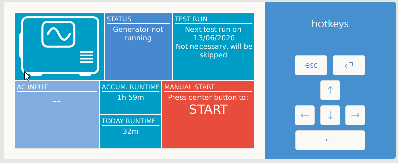
(Generator has been stopped manually on the generator)


Problem 2: The AC Input (wired in to AC2) on the generator screen does not show AC Voltage until the AC1 is disconnected. Regardless, the AC Input should show voltage regardless if its the main line. The generator screen context is all about the generator. If I want to see the main voltage I can go back to the Main overview


Problem 3: Main Screen - I want to see voltage and amperage with my shore power. I know I can do the math but having some extra data to reflect the wattage wouldn't hurt anything. At least give me the option to display the information in the green and red boxes. Running Auto Transformers so the voltage is at 240v which is what I want to see. It helps remind me of what is running. With 2 Auto Transformers, 50amp, 30amp and a auto switch I want to see more voltage/amperage of those components.


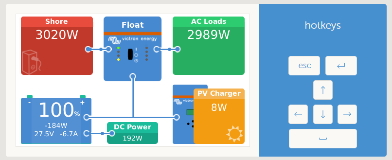
Problem 4: Main Screen - I have a DC/DC Alternator charger and a 24v to 12v charger but the main screen can't tell me where and how much voltage/amperage are coming from those sources. The above screenshot doesn't reflect my 2 other 12v systems, why not? The main screen has a great start but if it can't tell me where power is coming from outside of solar or generator then it seems to be lacking a lot. Both my Orion TR 24/12 and Orion 24/12v 70amp are lacking data on this screen. I have multiple shunts and wouldn't mind adding more shunts but without the VE ports and the ability to show them on the main screen what good would they be?


Problem 1 is my biggest issue but the rest need to be resolved to make a Cerbo GX capable of taking over the brains of my RV.

cerbo gx
mainscreen.png (44.2 KiB)
generator.png (34.8 KiB)
generator2.png (35.5 KiB)
generator.png (34.8 KiB)
1 comment
2 |3000

Up to 8 attachments (including images) can be used with a maximum of 190.8 MiB each and 286.6 MiB total.

bowpay avatar image bowpay commented ·

Btw if you guys release an SDK for the Cerbo GX I'll right my own software to allow me to visualize the data points.

0 Likes 0 ·
3 Answers
ben avatar image
ben answered ·

(In the future, please break your separate problems up into separate Questions, so they get answered more easily and so the software can index them better.)

For Problem 2: the inverter doesn't work that way. Only the active AC input is reported by the hardware.

2 comments
2 |3000

Up to 8 attachments (including images) can be used with a maximum of 190.8 MiB each and 286.6 MiB total.

bowpay avatar image bowpay commented ·

Thank you! I will do that. Problem 1 is my biggest issue.

0 Likes 0 ·
ben avatar image ben ♦ bowpay commented ·

Sorry I couldn't help you on Q1. I have a similar setup that can easily get "out of sync" with the actual generator state, but I don't use a digital feedback pin to supposedly report state back to Venus like I think you do, so I think you're seeing something different (maybe a bug). Especially if you see the correct gen state somewhere in one of the menus.

0 Likes 0 ·
ben avatar image
ben answered ·

For Problem 3, if you're making a feature request, cool. If you just want to make it work yourself, you can find examples where others have modified the QML layouts to display data differently over in the Modifications section. The UI is completely available to you if you go dig around in Venus OS. (That doesn't mean it's easy or fun to change, at least if you're not a Qt whiz already.)

I'm actually interested in why you have two ATs in your system, but it's unrelated to this problem. Just curious, since I also have a large RV system running at 240V (but with only one AT).

2 comments
2 |3000

Up to 8 attachments (including images) can be used with a maximum of 190.8 MiB each and 286.6 MiB total.

bowpay avatar image bowpay commented ·

Gotcha. Really rather find something out of the box. Don't really have the time to invest right now. 1 AT is used to step down after the Quattro and the second steps up from the generator or the 30amp shore to the Quattro. Works out great.

0 Likes 0 ·
ben avatar image ben ♦ bowpay commented ·

Interesting design!

0 Likes 0 ·
ben avatar image
ben answered ·

For Problem 4, you would definitely need more hardware before you could even start thinking about displaying data that you're currently not measuring.

You can write your own drivers for Venus which will interface to anything you can find a way to get connected. I don't know if a single Venus can source multiple shunts (BMVs) natively, but anyway you'd need to do some heavy customization on the UI as well.

For the kinds of things you're talking about, you are outside of the design envelope of the Venus Qt UI. You may want to have a look at the MQTT -> Influx -> Grafana sample docker image that sucks all the (available) data out of Venus and gives you a more expressive tool to create your own dashboards.

I wouldn't hold your breath for any of the things you've described to come natively to Venus OS in the near future.

2 |3000

Up to 8 attachments (including images) can be used with a maximum of 190.8 MiB each and 286.6 MiB total.