question

enya avatar image
enya asked

MPPT 75/50 not reaching desired charge and float voltage levels


Hi, I recently (last week) commissioned new battery banks.

12 x 6v 250Ah AGM Full River (1500 Ah).

Adjusted the MPPT 75/50 from old wet cell to AGM. Moved from Preset (2) Default, to Preset (3) AGM Spiral, as this was the only preset for 14.7v Absorption (which is the Battery Manufacturers specs).

Then manually adjusted float from preset 13.8v to 13.65v (again Manufactures spec) this moved the MPPT into custom programming. There is ample solar power being generated (4 x 327w SUNPOWER PV Panels)

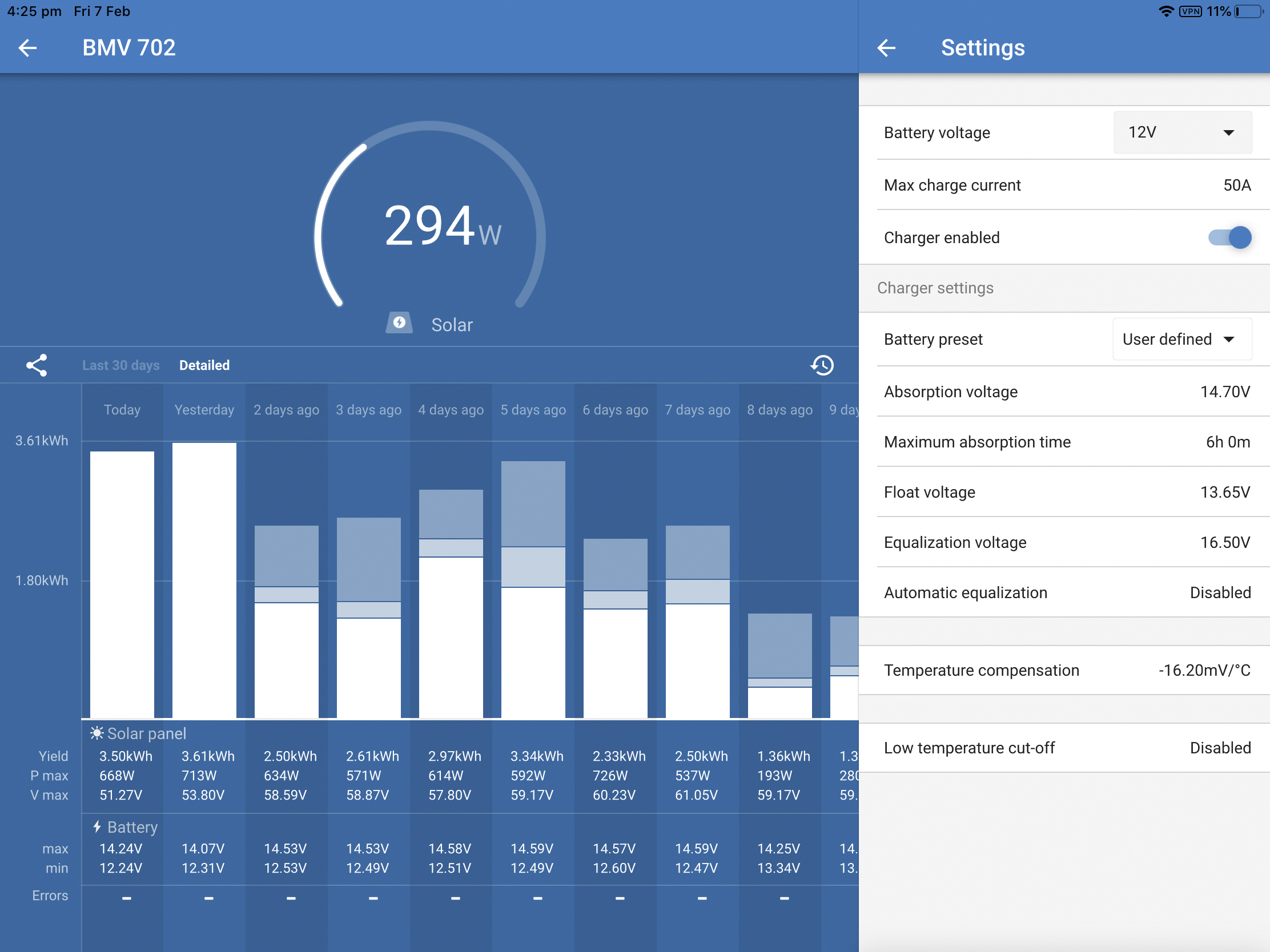
Attached are the VRM portal views for the past few days and a longer-term week view, plus voltage at shunt. I have also attached a diagram of the wiring. I will be moving to DCVV shortly.

Maximum voltage output reported by MPPTs is 14.4v ~ 14.5v (VRM) and Floating at 13.44v (VRM)

Maximum voltage seen at shunt is 14.16v (VRM)

(disregard the voltage max on second BMV, historical from old wet cells and faulty aux high power (160A) alternator.

I understand that the MPPT will default to Absorbtion time interval of 1 hr.

I have measured using MM voltage at output of MPPT to what it reports in Victron Connect. I am seeing a difference of 0.08v higher on VicCon vs MM

I am seeing a 0.05v difference between my MM and the BMV702, VicCon showing higher.

During a period of monitoring on VicCon BMVs showing 12.97v while MPPT showing 13.15v (Delta 0.13)

I can accept that there will be a difference from the output of the MPPTs to that seen by the BMV shunts, but this will be (should be minimal, as I have 70mm' AWG 2/0 gauge cable and total run length 6.48m POS and 6.68m NEG.

While moving to DVCC will align the Voltage and Temp to the MPPT. I am a little concerned why when I have programmed the MPPTs for 14.7v Abs and 13.65 float, that the MPPT don’t get above 14.1v at the battery and float at 13.44v

Thoughts?

ENYA.pdf

Voltage at Shunt.pdf

Absorb 5-2-2020.pdf

Absorb 5-2-02020 week profile.pdf

MPPT ControllersVRM
2 |3000

Up to 8 attachments (including images) can be used with a maximum of 190.8 MiB each and 286.6 MiB total.

1 Answer
Justin Cook avatar image
Justin Cook answered ·

@Enya, that's a very long run for DC cabling; even using the stated 2/0, the voltage drop (at 50A) to be expected over a ~14m round-trip distance is ~1.53%, and, from what I can tell, your stated values calculate out to a ~1.04% drop - which is really quite good, although somewhat to be expected given that I'm calculating at 12v when the v is really 13-14... taking true v into account, you're basically spot-on to the drop expected over that cable at that distance.

Bottom line: the components themselves appear to be working as should be expected. There are three basic options for countering the voltage drop that you're seeing: 1. Move the SCCs closer to your battery bank, thus decreasing the round-trip distance your existing cables are running and therefore decreasing voltage drop; 2: Increase your cable gauge between the SCCs and the batteries, thus decreasing voltage drop over the round-trip distance that you currently have; or 3: Dial up your voltages at the SCC to account for the voltage drop over the existing cables at the existing round-trip distance.

6 comments
2 |3000

Up to 8 attachments (including images) can be used with a maximum of 190.8 MiB each and 286.6 MiB total.

enya avatar image enya commented ·

Hi Justin, Very much appreciate your response and advice here. Wow I thought i had had done a fair job with the replacement cabling. but sounds like I should have upped the gauge somewhat ( more $ ). ( should have seen the mess I inherited. Starboard side was twice as long, half the gauge and not tinned. Port side only a few meters in length causing totally unbalance charge and loading)

Of the 3 options you suggest the first 2 are not viable. The 3rd is likely the best option, with use of DVCC to do the dialing ,rather than a fixed adjustment.

Why would the float not run at the desire lower rate, this would not be caused by voltage drop over the cable length?

Thx Enya.

0 Likes 0 ·
Justin Cook avatar image Justin Cook ♦♦ enya commented ·

@Enya, I'm a bit confused by that as well (though I can't quite read your float voltages from your VRM screenshots, I'm taking your word for their values)... have you tried measuring voltage at the MPPT battery terminals while they're in float? I'm wondering if the MPPTs are really floating at the voltage being reported in VRM or if there's perhaps a slight discrepancy between actual voltage (measured at the MPPT terminals) and reported voltage after being transmitted though the VE.Direct USB Interfaces that I think I see on your system (correct me if I'm reading your schematic incorrectly).

I haven't personally heard of the VE.Direct USB Interfaces causing any kind of reporting discrepancies, but then again at a difference of two-tenths of a volt between reported voltage and programmed voltage, I'm not sure that anyone would have particularly noticed... thus why I'd like physical confirmation of actual output float voltage.

0 Likes 0 ·
enya avatar image enya Justin Cook ♦♦ commented ·

Hi @Justin Cook

Will do in a few hours , sun just came up here in Oz so system is in Bulk currently.

Regards

Enya

0 Likes 0 ·
Justin Cook avatar image Justin Cook ♦♦ enya commented ·

@Enya looks like I'll be off-duty before you likely get the answer (I'm GMT-8) but tag me if you come up with anything interesting and I'll take a peek tomorrow morning :)

0 Likes 0 ·
enya avatar image enya enya commented ·

Thx Justin,

Unfortunately the system behaved a little odd today. For whatever reason the MPPTs did not come out of Bulk the whole day. I can't see it being related to the following , but its the only change.

While waiting for the system to move to float, I corrected a parameter in the BMV wrt capacity 1500 Ah down to 750 Ah, as I had not considered each bank independently with its own BMV/Shunt. This caused the SOC to change (down) as expected. Once it reached 13.2v with a tail current of less than X% for a period of 3 minutes, it reset/Synchronize to 100% as defined in the manual.

I also adjust a low voltage setting alarm. All of these were on the BMV's so unrelated to MPPT's?

Anyway didn't get an opportunity to measure during float. Will see what tomorrow brings.

All going well I will implement DVCC. I have reviewed the documentation. A lot of it is not applicable to my environment, However still a little confusing. May ping you if your around in the morning.


Regards

0 Likes 0 ·
enya avatar image enya enya commented ·

@Justin Cook

Hi there Justin,

I think I learnt what was going on with not getting out of Bulk. I believe the Solar/MPPTs were not able to get enough power to support both the ships running load and charge up the batteries. (The new bank is 10% larger) and I had moved off shore power which was supplying some 240V needs. This was in an attempt to simulate at sea conditions. I reverted back on the next day ,but it was midday by then and the batteries had discharged even lower from the prior night and the system failed to move into Absorption for a second day running.

All running back as per initial cut-over performance. I measured the voltage at the SCC output compared to that being reported real time on RemoteConsole.

ABSORPTION

MPPT1 RemoteConsole 14.51v

MPPT1 Multimeter 14.40v

MPPT2 RemoteConsole 14.52v

MPPT2 Multimeter 14.42v

Overall ~ 0.1 Volt difference.

FLOAT

MPPT1 RemoteConsole 13.46v

MPPT1 Multi meter 14.38v

MPPT2 RemoteConsole 13.50v

MPPT2 Multimeter 13.40v

Overall ~ 0.1 Volt difference


WRT to voltage not getting to the full desired 14.7v for Absorption. and 13.65 for Float. I have read that the Blue Solar MPPTs do run their own internal temp sensor. We are running at 29C~31C in the boat on the BMVs so I believe the SCC would see similar and are making some temperature compensation.

I found a historical view in Vic Con (but I have to use the Bluetooth dongle and disconnect the MPPTs from reporting Venus while testing) That the MPPTs have been charging to near the desired 14.7v See attached screen shot of 1 of the SCC.


Well having now read answer to

MPPT internal temperature and throttling information.

my assumption that temperature compensation by the MPPTs was answer to why we were not seeing the 14.7 (Charge/Abs) and 13.65 (Float) may have been wrong.

0 Likes 0 ·
mppt-scc-history.jpg (772.5 KiB)