question

bruce32466 avatar image
bruce32466 asked

Programmable relay, operating BP on aux2 based on condition of aux1

HARDWARE:

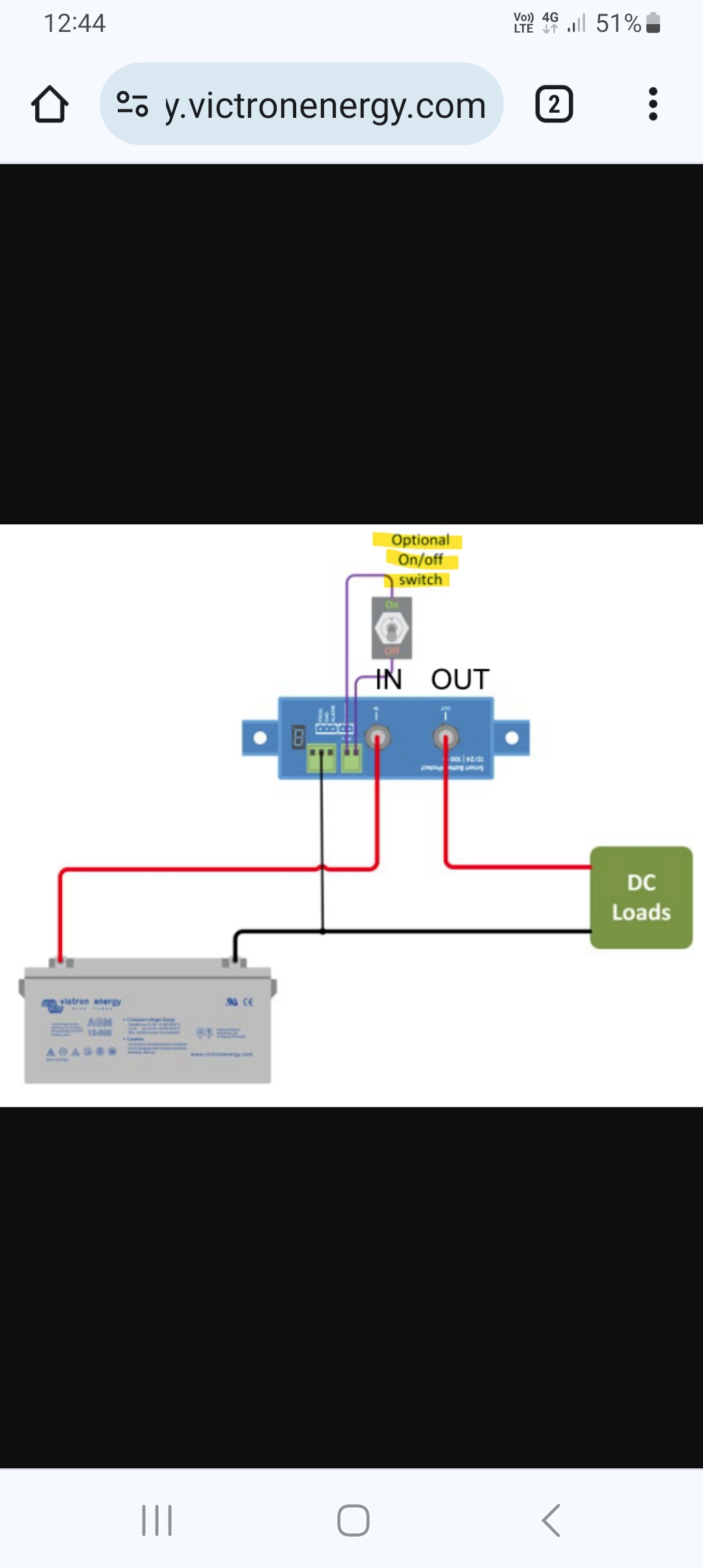
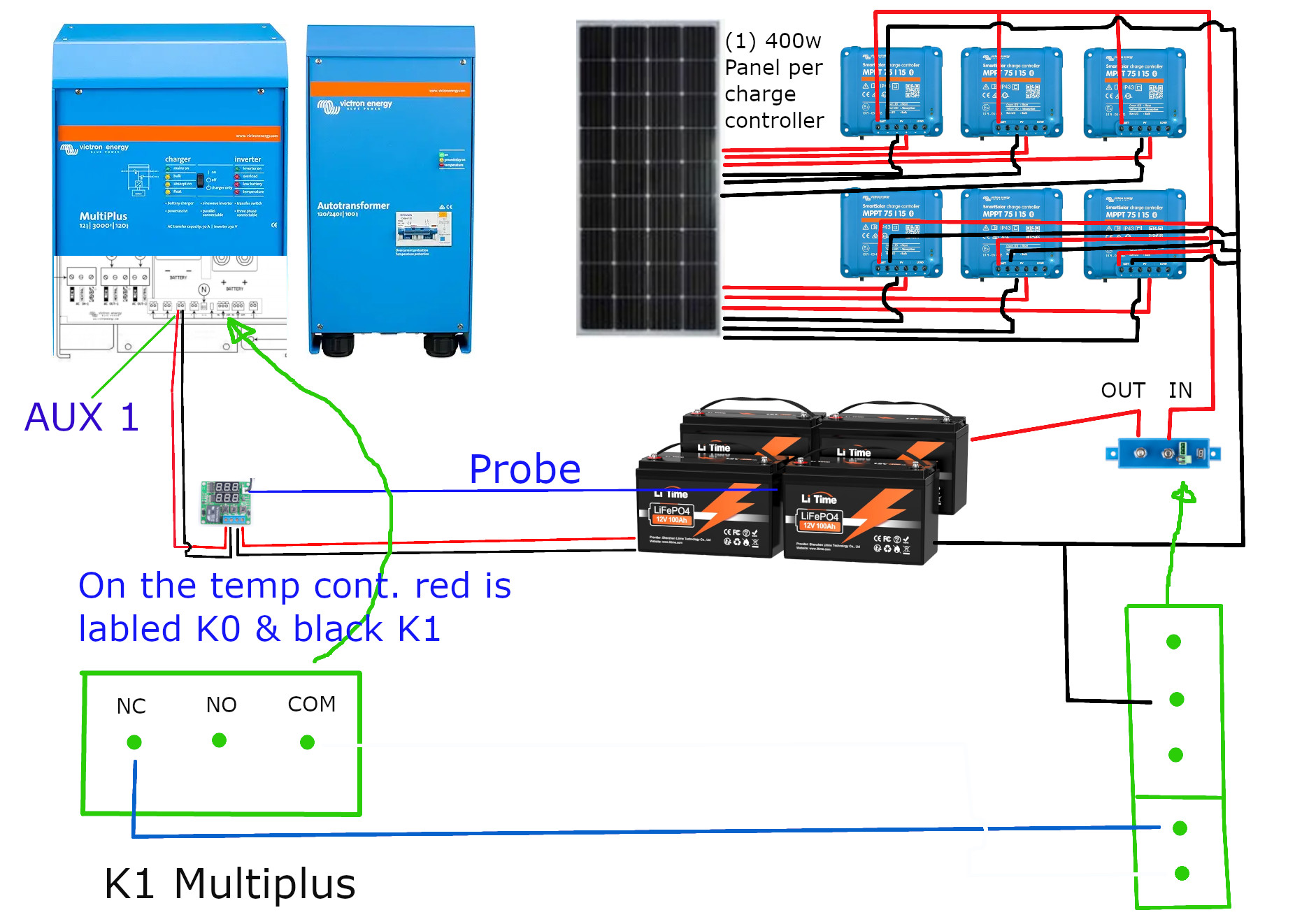
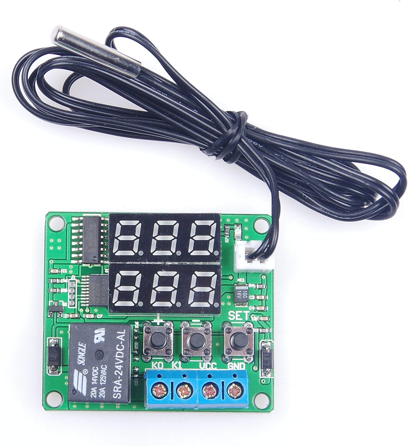
Here's what I have... A 3rd party temp controller turns on it's relay (closed) at 35* or less which is hooked up to aux1 on the multiplus 24/5000/120. when the batteries drop down to 35*, the multi stops charging as it should. I have the remote terminals of the victron battery protect BP 12/24 | 100 connected to aux2 which is operational. I have 6 BlueSolar mppt 75/15 charge controllers with 1 400w solar panel connected to each charge controller. the output of the 6 charge controllers are connected to the in terminal of the BP.

PROGRAMMING:

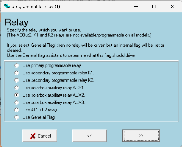
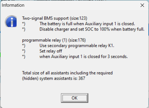
I have the "2 signal bms" assistant loaded at the top as first assistant. it is configured so when temp controller relay is on, charging is disabled on the multi. next assistant below the first one is a "programmable relay". It's settings are as follows: use solarbox auxiliary relay AUX2 selected, Set relay on is selected, Input signal (auxiliary 1, auxiliary 2 or temperature sense input) selected, did not select any extra drive options, and then set "When auxiliary input 1 is open for 3 seconds. Then the last assistant is another "Programmable relay (1)". It's settings are as follows: use solarbox auxiliary relay AUX2 selected, Set relay off is selected, Input signal (auxiliary 1, auxiliary 2 or temperature sense input) selected, did not select any extra drive options, and then set "When auxiliary input 1 is closed for 2 seconds. with this config the multi stops charging like it should but the battery protect still passes current to the battery. I tried swapping the order of the 2 programmable relay assistant and it made n difference. I need the battery protect to disconnect from the battery. My batteries do not have thermal protection. I looked high and low to no avail and I wold really appreciate if someone could please let me know where I'm wrong here or if there's a better way to achieve this with the current hardware? Yes I have read the assistants doc at victron's site, but I couldn't figure it out with that. A little dense I guess.

Thank you in advance.

God Bless!
screenshot-2024-07-25-123809.png

Relay
4 comments
2 |3000

Up to 8 attachments (including images) can be used with a maximum of 190.8 MiB each and 286.6 MiB total.

Do you have a "solarbox"?

As far as I know that is a very old device that isn't available anymore.

0 Likes 0 ·
bruce32466 avatar image bruce32466 Matthias Lange - DE ♦ commented ·

What other option do I have in the list below to use aux2?
screenshot-2024-07-25-123801.png

0 Likes 0 ·
Matthias Lange - DE avatar image Matthias Lange - DE ♦ bruce32466 commented ·

Look into the manual to see what relais you have.

You definitely have the "primary programmable relay". Some devices have the "secondary programmable relay K1" and K2.

0 Likes 0 ·

Multi usually comes with a t sense cable. Are these lithium batteries?

You can use the t sense to stop charging under a certain temp.

You can also daisy chain wiring so if one opens they are all open.

0 Likes 0 ·
7 Answers
bruce32466 avatar image
bruce32466 answered ·

I didn't want a daisy chain the wiring so I can keep the relay turned off on the temperature controller. And I'm really not interested in purchasing more stuff when I already have everything I need. To use t-sense I assume I would have to buy more equipment. And as stated earlier, the charger turns off on a multiplus fine. I just need to signal the BP to disconnect so solar power so they don't charge the batteries. Is it not possible to program aux 2 to shut off the BP when aux 1 is closed?

2 |3000

Up to 8 attachments (including images) can be used with a maximum of 190.8 MiB each and 286.6 MiB total.

bruce32466 avatar image
bruce32466 answered ·

Alexandra.

Thank you for the response. I bought this multiplus about maybe 6 yrs ago. I don't recall it coming with a temp sense and even if it did, I couldn't tell you where it is anyway. I was running it on a tesla medel s battery module connected to an electrodacus bms but decided to go with something safer (lifepo4). I also placed a BP between the MPPTs and the battery and would still need a solution to stop charging from solar anyway. Regards.

2 |3000

Up to 8 attachments (including images) can be used with a maximum of 190.8 MiB each and 286.6 MiB total.

bruce32466 avatar image
bruce32466 answered ·

In the manual, Appendix A is:

Terminals for: (left to right)
Voltage sense
Temperature sensor
Aux input 1
Aux input 2
GND-relay
Starter battery plus + (starter battery minus must be connected to service battery minus)
Programmable relay contacts K1
Programmable relay contacts K2

If I understand this correctly, I have 2 programmable relays, k1 & k2 and need to use one of those. So I moved the the wires to k1 nc & com as the solar should be normally charging, changed the "Programmable relay" setting to use k1 and stil will not turn off the BP.

screenshot-2024-07-25-164657.png


1 comment
2 |3000

Up to 8 attachments (including images) can be used with a maximum of 190.8 MiB each and 286.6 MiB total.

You have to set the relay to ON to open the NC.

And you also have to program another assistant to switch the relay to OFF.

0 Likes 0 ·
rayclout avatar image
rayclout answered ·

I'm sure you're aware of this but I'll ask anyway...just to tick the box

Are you aware that the K1&2 relays are open collector style, and aren't wired like a normal relay?


2 comments
2 |3000

Up to 8 attachments (including images) can be used with a maximum of 190.8 MiB each and 286.6 MiB total.

bruce32466 avatar image bruce32466 commented ·

Rayclout.

Thanks for responding. No, I'm not aware of that. What is the purpose having a programmable relay if I can not control something with it? You'll have to forgive me but I'm pretty naive. When I see a relay I assume it's function is to make an electrical connection to turn things on and off. Anyway I may have jacked up my BP.

Look. What I need is a way to shut down solar charging on the cheap as I'm on a limited income so I can't afford all the fancy Victron equipment. The only reason I have the Victron equipment now is because I bought it all when I was working but now retired. My original post here describes my setup pretty well. It's pretty simple. I assume a BP is not the way to go about this. any suggestions?

Regards.

0 Likes 0 ·

@rayclout If he have the old style MultiPlus K1 and K2 are real relays.

Only the MultiPlus-II has the open collector K1.

@bruce32466

0 Likes 0 ·
rayclout avatar image
rayclout answered ·

Here is a pretty good description and schematics of how you would go about wiring up the k internal relays.

The load mentioned on the schematics would represent the coil of an external relay.

So even if the programming code logic you have written is correct, without the wiring correct it wont work.

Minimum you would need is an external relay, sized to your needs.

BTW....any switch can be replaced with a relay, so going by what others have shown above, you could replace the remote switch on the BP with the contacts of a switching relay, and the coil operation done by one of the k internal relays of the multi.

Any chance of seeing a schematic of your system


Screenshot_20240510_135857_Firefox.jpg


1 comment
2 |3000

Up to 8 attachments (including images) can be used with a maximum of 190.8 MiB each and 286.6 MiB total.

bruce32466 avatar image bruce32466 commented ·

Thank you so much! It's late for me but I will put something together tomorrow.

Thanks again, God bless.

0 Likes 0 ·
rayclout avatar image
rayclout answered ·

The optional on/off switch on this schematic can be replaced with a relay that you program one of the internal k relay to switch. This would then turn the BP off and isolate any dc load (read inverter or battery or both depending on what relay you use)screenshot-20240726-124419-chrome.jpg


5 comments
2 |3000

Up to 8 attachments (including images) can be used with a maximum of 190.8 MiB each and 286.6 MiB total.

bruce32466 avatar image bruce32466 commented ·

Thanks again.

Here's a crude schematic. Let me know if there's enything else I can provide

mp5000.jpg

Here's the temperature controller:
tempcont.jpg
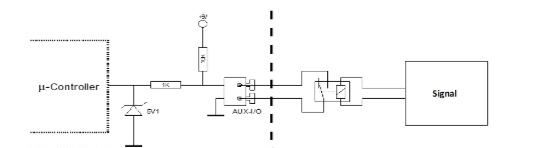
And the assistants config:
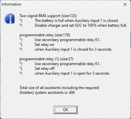
screenshot-2024-07-26-110331.png

Regards.

0 Likes 0 ·
mp5000.jpg (398.8 KiB)
tempcont.jpg (174.9 KiB)
bruce32466 avatar image bruce32466 bruce32466 commented ·

One of the lines didn't show up on the schematic and didn't see a way to edit this comment.

mp5000.jpg

0 Likes 0 ·
mp5000.jpg (402.8 KiB)
Matthias Lange - DE avatar image Matthias Lange - DE ♦ bruce32466 commented ·

Just for testing:

Remove the temp controller and use a short wire to bridge the AUX input.

Do you have selected a grid code? Some grid codes uses AUX 1 as a signal.
Try using AUX 2 or T-sense as input.

0 Likes 0 ·
bruce32466 avatar image bruce32466 Matthias Lange - DE ♦ commented ·

Matthias.

Thank you for the response. This setup is in an RV so I have "none" selected for the grid. When the temperature drops, the temp controller relay closes and the multiplus does stop charging. This part is working fine. I just need a way to disconnect the solar charge controllers so they don't charge the battery when the temperature drops as well. I did ask in another post whether this arrangement is an acceptable use of a BP but have not gotten an answer yet. But regardless with the way it's wired and programmed, the blue flashing light on the BP turns off when the temperature drops, but for whatever reason I'm still getting current across the BP.

Thank you.

0 Likes 0 ·
rayclout avatar image rayclout bruce32466 commented ·

Try moving the wire on the K1 NC terminal to K1 NO terminal and give that a go.

0 Likes 0 ·
rayclout avatar image
rayclout answered ·
  1. First off, yes the BP turn off function is quite acceptable to do what you want. I assume in the guts of the device is an SSR......although dont quote me on that

The two images attached show you the logic you want

The first image shows your connection from the temp controller to the aux in terminal.

When the temp reaches your setpoint, the relay on the temp controller closes. This closure connects a 5v signal to an interrupt port on a microcontroller inside the multiplus which performs the function set by the assistant. You have this wired correctly and is why it works.

The second image, while not showing exactly your situation, will explain the operation you need

The circuit shows a fan connected via K1 NO and COM, to a battery and will turn on and run when K1 is switched.

What you need is a simple switch across the BP terminals, that once closed will isolate the Input from the Output terminal resulting in a disconnection of the mppts from the battery.Screenshot_20240727_085029_Chrome.jpg

screenshot-20240727-085704-chrome.jpg


1 comment
2 |3000

Up to 8 attachments (including images) can be used with a maximum of 190.8 MiB each and 286.6 MiB total.

bruce32466 avatar image bruce32466 commented ·

Rayclout. Thank you. It's working!

0 Likes 0 ·

Related Resources

Additional resources still need to be added for this topic