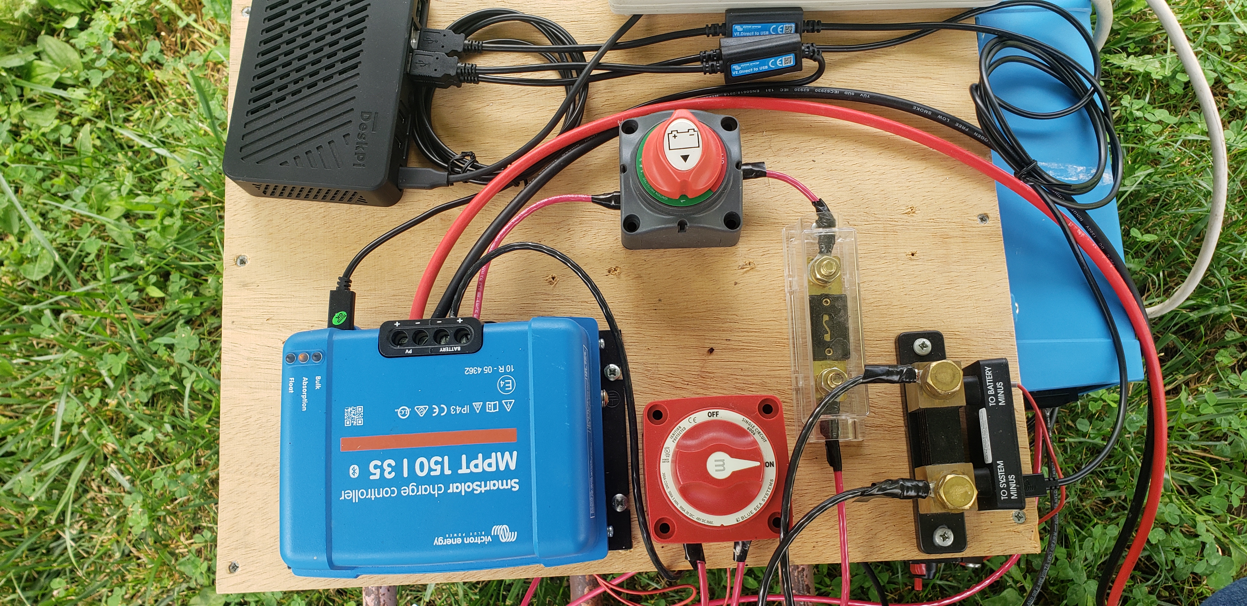
To start off let me paint the picture of this small setup 3 320W solar panels in a 3s1p to 150V35A victron SmartSolar Mppt with a Victron Smart Shurt and Victron 48V/500W inverter.
The key issue is the Smart Shunt State of Charge. The Smart Shunt I have is the 500A 50mV model. I want to understand why I cant make this reset to 100% when clearly it is going through full cycles, and As I have attempted to tune this setup. I cannot understand why it wont ever go back to 100% SOC even though the system so far ~ 1 week + into use is working as expected and device has not gone offline even though now my SOC states it is at 0%. Clearly it is charging and keeping the battery charged otherwise this would not work given I have pulled ~5x the Ah of the bank of battery I have attached.
Technical details:
I have the following.
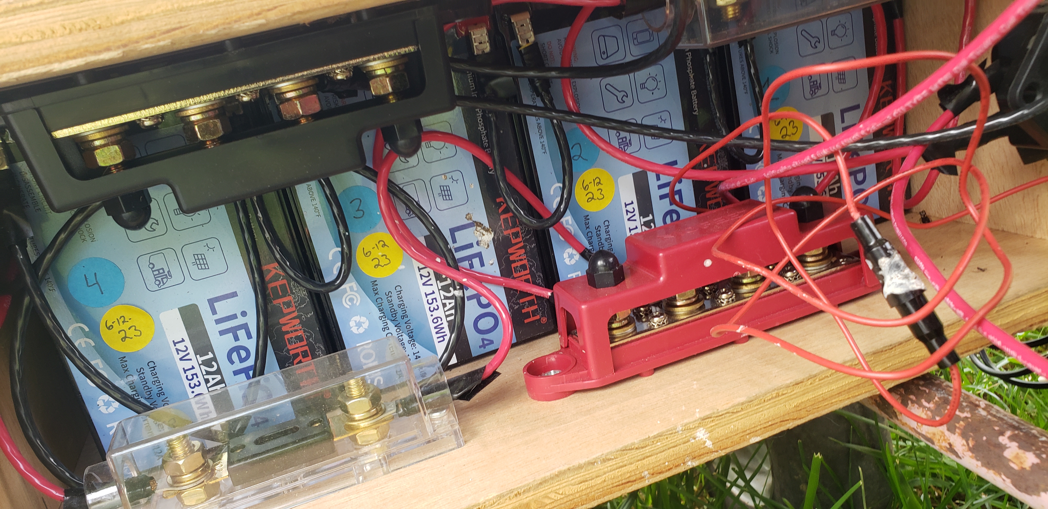
8 x lifepo4 12.8V 12Ah Lithium Battery - LiFePO4
Link to battery: https://www.amazon.com/dp/B0CMQB4B48?psc=1&ref=ppx_yo2ov_dt_b_product_details
They are setup to be a string of 48V ( I understand the voltage is actually higher ) but it is a 48V system.
Each battery has the following specs
12V – 12AH
153.6Wh each battery
Nominal Voltage 12.8
Voltage range 10-14.6
Charge voltage 14.6
Max charge current 15A
Recommended Charge Current 7A
Max discharge rate 15A
This setup is configured as a 4S2P ( are 4 in a Series and 2 in parallel ) making this a 48v at 24Ah bank of batteries.
I recently setup a Pi 4 with Venus OS so I can remote monitor vs local Bluetooth. I have this setup and online so I can look at devices. ( data from online and Bluetooth local is same data )
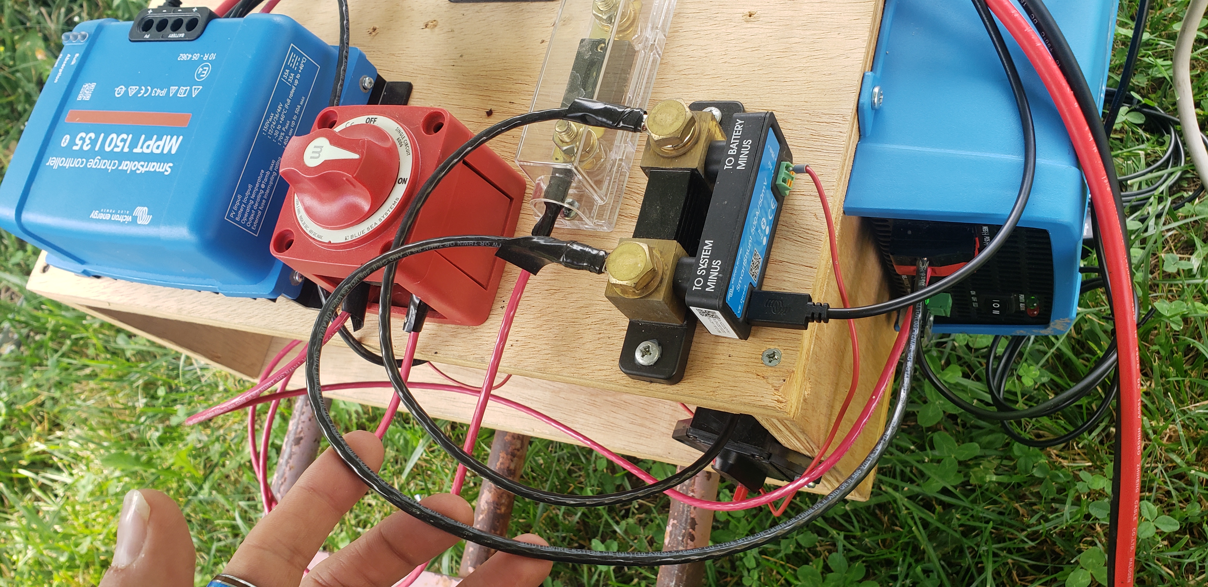
The key issue is the Smart Shunt State of Charge. The Smart Shunt I have is the 500A 50mV model.
The above battery bank has a bus bar on Negative and positive. So I can attach items as needed.
The smart Shut comes off the Bus bar.
I have a set of 3 solar panels in series connected to a SmartSolar Charger which is the MPPT 150/35
Each panel has the following specs which combined output a Nominal Voltage of ~97V to 103V
Each are Trina Solar 320W industrial panels. ( each tests good with all known tests I can preform )
Pmax – 320W
Vmp- 33.4
Imp -9.58
Open Circuity Voltage ( Voc ) – 40.3
Short Circuity Voltage ( Isc ) 10.2
Max Seriese Fuse – 20 A
Per the Smart Solar history tab Daily I am generating on average 360-370Wh of Yield with a Pmax of 130 to 470 give or take.
My only load is the raspberry pi at a constant ( per smart shut ) 17-20 Watts of usage 24 hr a day ( this takes into account the draw of the inverter which is a Victron 48/500 120V inverter set to Non ECO mode.
All items in this whole setup are Victron ( minus the obvious battreys, pannels and fuses )
As of this writing the Smart Solar shows my panel voltage is 99.12V and current is 0.2A
The battery is at 68.8V with a current of 0.30 A in the Absorption state
In the Smart Solar settings the settings are as follows
Battrey Voltage 48V
Max Charge Current 12A
Charger is enabled
Battrey preset is Smart Lithum ( LiFePo4 )
Expert mode is off
Absorption rate is 56.8V
Float is 54.0 V
Low Temp cut off is 41
The remaining settings are disabled as this is a preset.
My load output is operation mode Battrey Life
Streetlight is off
Switching to smart shut here is my current information
Volrage at battery which ( at this time is in absorption mode from MPPT ) is 56.8V
Current is -0.3A
Power is -17W
Total Consumed Ah is -54.7Ah
Time Remaining is 0m
Which shows the Low SOC Alarm in red
Using history I have deepest discharge os -55Ah and Communitive discharge of -111Ah
Discharged energy is 6.0Kwh
Last tiem since full charge is now 6D and 20Hours soon to be 7 Days
The following are the smart shut settings
Battrey capacity is 24 Ah
Charged Voltage is 53.9V
Discharge Floow is 10%
Tail Current is 5%
Pukert Exponent is 1.05
Charge Efficiency factor is 98%
Current threshold is 0.10A
Time to go average is 3M ( min )
Current SOC 0%
Knowing a few things
This setup is fune for my application.
With a 500W inverter at 48V the max amp I can have is 10.416 max A draw which is below the Inverter and battery limit.
I would love to know more about why the SOC cant or seems to not go back to 100% I can provide more details as needed.
Thanks Jacob