question

rvnomad avatar image
rvnomad asked

BMV-712 goes from 64% to 100% when charging and other mysteries

My setup:

  • 50-amp RV with Onan 5500 generator
  • Renogy 400 watt solar panels with Victron SmartSolar controller
  • Battleborn 2x100 AH batteries
  • Victron MultiPlus II 2x120 inverter charger
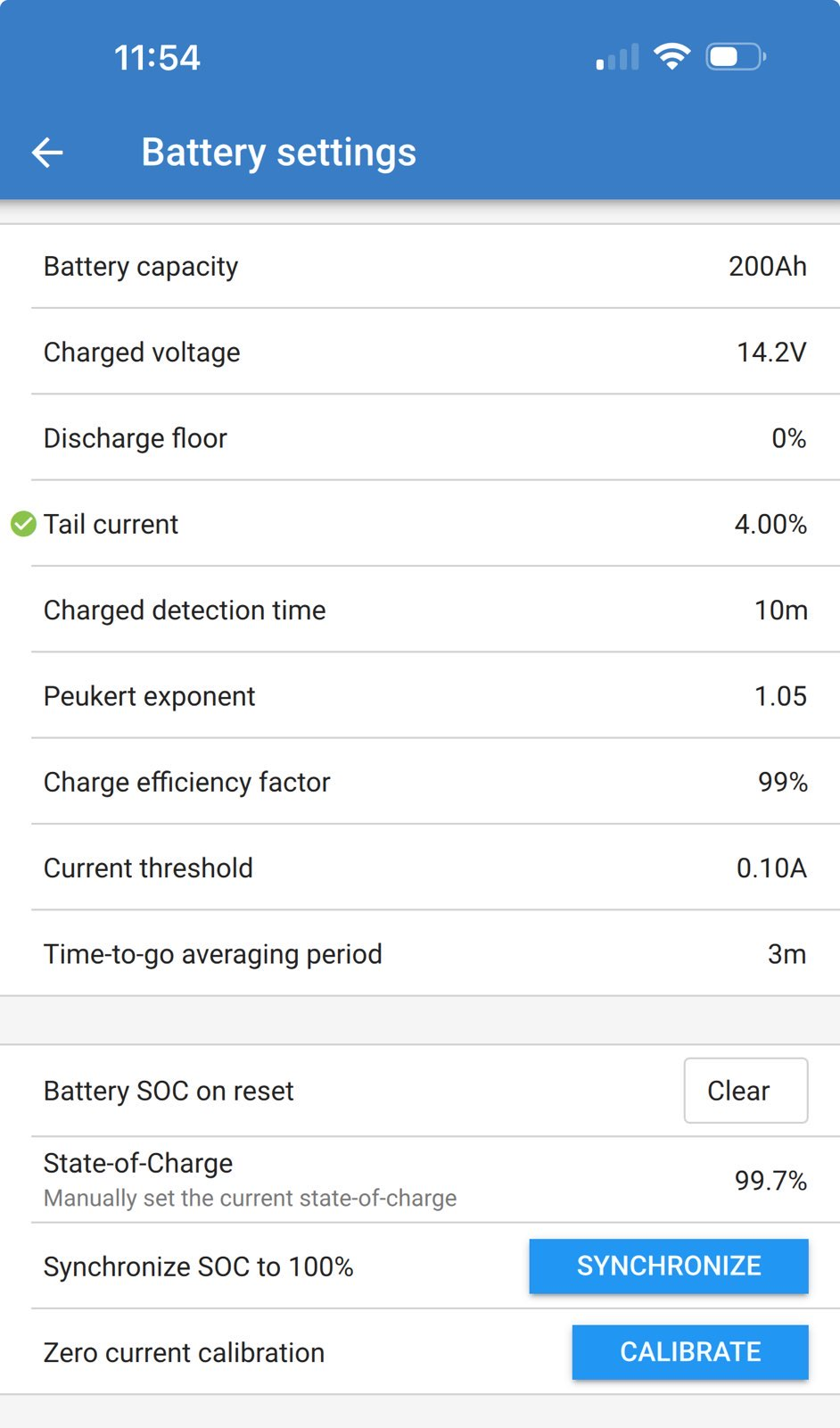
  • Victron BMV-712 battery monitor.

I have several questions about how this all works in practice. I wonder if the BMV-712 is telling a true story. Here are some puzzling screenshots:

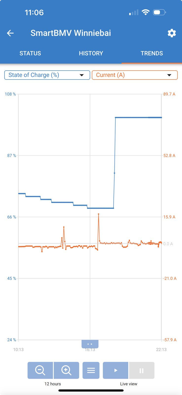
1: This occurs frequently: when charging from AC power, the SOC remains stuck at 64% for a while and jumps to 100%, never in between. I never know if the batteries are fully charged or not.

1717654016187.png


2. When the MultiPlus II is performing a bulk charge, there can be considerable discrepancies between what the MultiPlus II and BMV-712 report. Whom to believe?


1717654447774.png


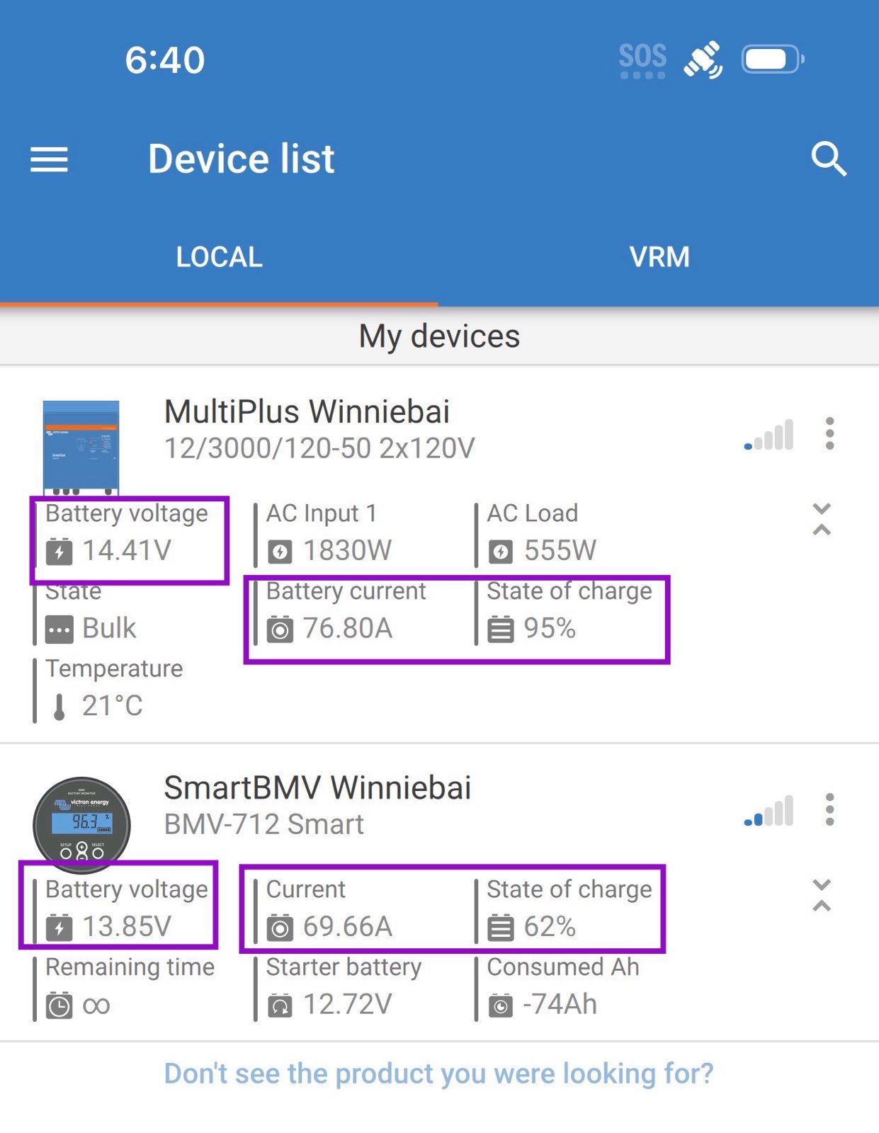
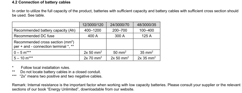
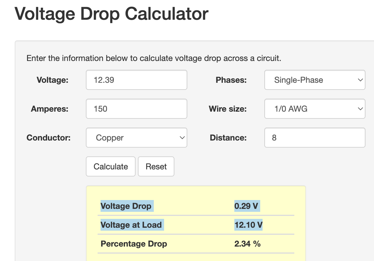
The MultiPlus and battery bank are about 6 feet apart due to the RV layout and are connected with 0-gauge cables, which every online gauge calculator assures me is sufficient. Is this kind of voltage drop normal to see with these high currents?

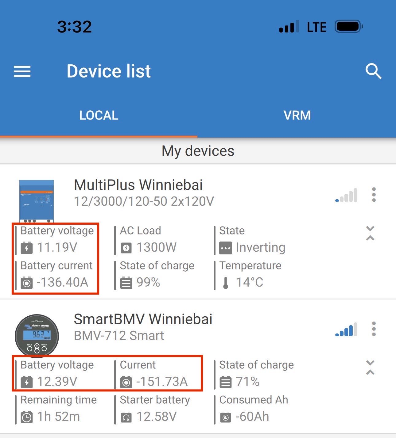
3. I see the same discrepancies when I run a microwave. The voltage at the inverter is usually 1.2 V below the voltage at the battery.

1717654765166.png


All thoughts are appreciated for understanding this. At the end of the day, I'd like to break camp with my RV and know that the batteries are really at 100% instead of some lesser number.

Multiplus-IIBMV Battery Monitor
1717654016187.png (278.0 KiB)
1717654447774.png (712.2 KiB)
1717654765166.png (673.4 KiB)
2 |3000

Up to 8 attachments (including images) can be used with a maximum of 190.8 MiB each and 286.6 MiB total.

3 Answers
snoobler avatar image
snoobler answered ·

Please confirm the BMV is the ONLY thing attached to the battery bank (-) terminal. All current in and out of the battery must pass through the shunt.

If you are not connected to a GX device, the Inverter SoC will always be wrong as it can't see any charging done by anything but itself, i.e., it can't see what's added by solar.

The two devices sync to 100% very differently. The MP sets a given % when bulk is finished. The BMV sets to 100% based on charge and tail current.

If you're having issues with false syncs (you are), you need to set your BMV charged voltage to 0.2V below your absorption voltage (guessing it's 14.4V), and your tail current to 4%.

It is a concern that you are showing a 0.55V difference between the MP and BMV voltage. If all your connections are good, and you aren't generating any heat between the battery terminals and inverter terminals, you're probably good.


1 comment
2 |3000

Up to 8 attachments (including images) can be used with a maximum of 190.8 MiB each and 286.6 MiB total.

rvnomad avatar image rvnomad commented ·

Thanks, the Charged voltage was already set to 0.2V below the absorption voltage of 14.4V


I have changed the tail current to 4% as you recommended. Here are all my BMV settings:


1717656952143.png


I'll inspect the cabling again and try to measure any heat with a heat gun.

0 Likes 0 ·
1717656952143.png (452.4 KiB)
pwfarnell avatar image
pwfarnell answered ·

I believe that the DC current monitoring in the Multiplus is less accurate than the shunt, it does not have a shunt built in. I am sure that I read an answer on here that said the Multiplus DC current is calculated from the ac current and expected efficiency, but I am not sure about that.

Your voltage discrepancy is down to voltage drop, when your Multiplus is charging 70A it is 0.56V and when discharging 150A it is 1.2V, the numbers are perfectly proportionate which means you have too much resistance between your batteries and your Multiplus. Check all your crimps and terminals and any fuses have appropriate rating and connection and any isolation switches. Get out your digital multimeter and check voltage on both positive and negative cabling to identify where the voltage drop is occurring. The 3000VA 12V Multiplus should be connected with two parallel 0 gauge positive and two parallel 0 gauge negative cables. You say you have 0 gauge but do not spec if one or two. The manual states two pairs.

screenshot-20240606-091814-kindlephoto-419410407.png


2 |3000

Up to 8 attachments (including images) can be used with a maximum of 190.8 MiB each and 286.6 MiB total.

rvnomad avatar image
rvnomad answered ·

@snoobler and @pwfarnell, thanks for the useful suggestions! My findings from today:

1) I inspected the battery box and found that the installer had wired the solar panel controller's negative to the battery negative post. I moved this to the shunt negative terminal. The only other thing that is wired to the battery negative post appears to be the inverter's temperature probe.

2) Most battery cables appeared to be wired well, but one of them had the 0 gauge stranded wire inserted directly into the fuse terminal instead of being crimped into a lug first. I located a local welding supply shop and they will make a custom fit crimped cable for me tomorrow.

3) I tightened all the terminal nuts. None were loose.

4) I ran a test using a microwave, drawing 150A at the battery and scanned with an IR thermometer. The terminal that goes from the battery positive to the inverter definitely heats up, going from about 70 deg. F to about 110 deg F after two minutes of run time. No other terminal heats up. Does this mean that the 8-foot cable run from the batteries to the inverter is undersized?

5) Followup to (4): Every online gauge and voltage drop calculator predicts that 0 gauge should be sufficient for my application. Here is a typical one that predicts just a 0.29V drop for my run conditions. What am I missing? The installer also recommended using 0 gauge.

http://wiresizecalculator.net/calculators/voltagedrop.htm

1717737834673.png


The local welding shop may be able to make me 2/0 gauge cabling that I can retrofit, so this is definitely an option. But of course I want to make sure it will solve my problem as pulling cables through an RV is a fair amount of work.


1717737834673.png (89.5 KiB)
3 comments
2 |3000

Up to 8 attachments (including images) can be used with a maximum of 190.8 MiB each and 286.6 MiB total.

snoobler avatar image snoobler commented ·
Victron HATES DC ripple, so they over-spec their cables. While 2.34% may meet the commonly reference 3%, but between battery and inverter, lower is ALWAYS better.


Do you achieve the calculated voltage drop, or is it worse?


If you're only getting heat at one location, either you may have insufficient torque, or there is less thermal mass to conduct the heat. This may be the case at the inverter (+) terminal, but since it's not happening with the (-), that makes the (+) connection suspicious... BUT... +40°F isn't what I could call a major concern.


Ensure the cable terminal is in direct contact with the inverter terminal. You don't want a washer or anything between them. A washer between the nut and the top of the cable terminal is fine, but NOTHING is between cable lug and inverter terminal.


As posted by @pwfarnell Victron recommends 2X 50mm^2 (slightly thinner than 1/0). If you're only using the one cable, simply running an identical set of cables to connect to the other terminal might be easier then routing a new set of 2/0.


1 Like 1 ·
rvnomad avatar image rvnomad snoobler commented ·
During the microwave test, I'm getting an actual drop of 1.2V (according to the Victron inverter display on Victron Connect), instead of the predicted 0.29 V.


I will check for washers tomorrow. I measured the temperature in the battery box, about 8 feet away from the inverter. I haven't measured temperature at the inverter terminals yet. The hot terminal was in the battery box:

Battery Positive -> DC Fuse In -> DC Fuse Out -> Inverter Cable (this last one was hot). No other terminal was hot.


0 Likes 0 ·
pwfarnell avatar image pwfarnell rvnomad commented ·
You need to get a multimeter on there while you have a large current draw and measure the voltage at the battery and at the inverter to rule out a measurement error on one device, but as the voltage drop goes both ways with charge/discharge I do not think you have an offset error on one device. Then with current flowing measure positive battery to positive inverter and likewise for the negative. Then check positive battery to every positive terminal to further define voltage drop. That is how I worked through my 175A alternator to battery voltage drop.
1 Like 1 ·