question

joshua Richard Sabuni avatar image
joshua Richard Sabuni asked

Issues Connecting Three-Phase 8kVA Quattro Setup to Grid with EM24 Energy Meter

Hello,

I am currently experiencing an issue with my Victron system setup. The details of my setup are as follows:

  • Victron Equipment:

    • Three 8kVA Quattro inverters configured for three-phase operation
    • EM24 three-phase energy meter
    • Fronius Symo 15kVA inverter
  • Configuration:

    • The system operates correctly when off-grid.
    • The first Quattro's AC INPUT 1 is connected to Phase 1 of the grid.
    • The second Quattro's AC INPUT 1 is connected to Phase 2 of the grid.
    • The third Quattro's AC INPUT 1 is connected to Phase 3 of the grid.

Issue:When I try to connect the system to the grid, the Quattros do not connect to the grid, and the Fronius inverter throttles down.

Troubleshooting Steps Taken:

  • Verified connections from the Quattros to the grid phases.
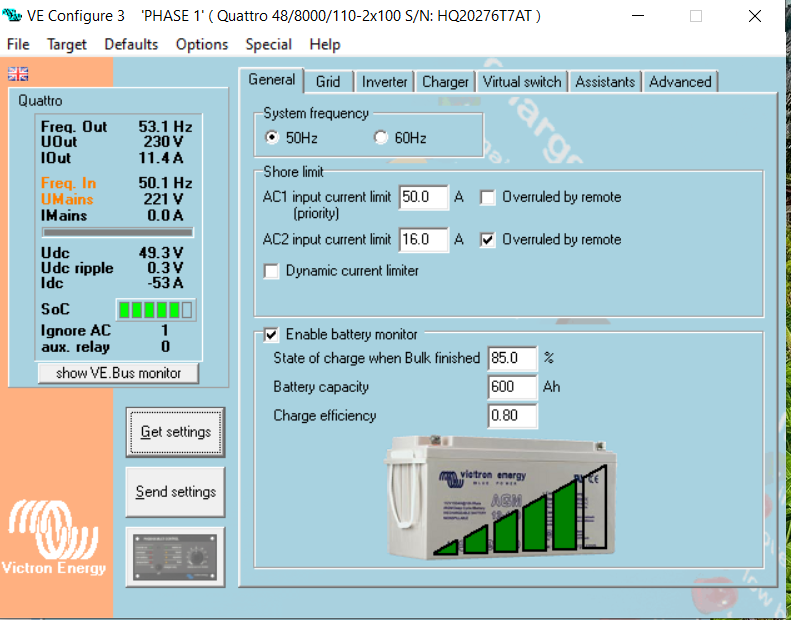
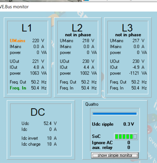
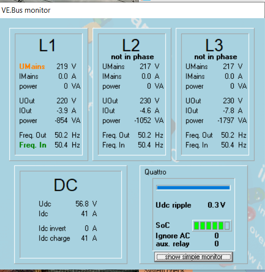
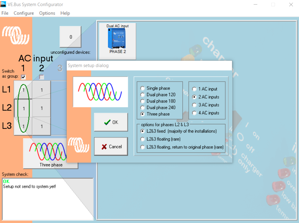
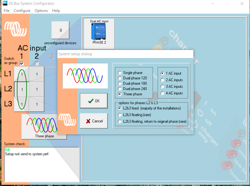
  • Checked configuration settings in the VE Bus Configurator.
  • Ensured the EM24 energy meter is properly installed and configured.
grid
2 |3000

Up to 8 attachments (including images) can be used with a maximum of 190.8 MiB each and 286.6 MiB total.

5 Answers
danielj avatar image
danielj answered ·

Hi joshua.

There can be a couple of reasons for a Quattro unit to not accept an AC connection.
Is the AC connection you are connecting to an Utility or a generator connection?

Victron units typically do not connect to an AC connection when the voltage or frequency parameters fall out of the accepted range. You can see what the reason is that a unit is not connecting by using VE.configure. The "freq In" or "Umains" values will show red or yellow when the values are out of range.1716546331049.png

There are settings in VE.configure that you can change to widen these ranges. NB! changing these parameters might result in the unit no longer conforming to your local gird standard.


Other problems such as phase rotation would also prevent a connection, but this usually pops up as an error on the GX device.

Physical wiring problems on the input might also contribute. The input neutral of the units must be connected at a common point with as little difference between cable lengths and thicknesses as possible.


1716546331049.png (3.5 KiB)
2 |3000

Up to 8 attachments (including images) can be used with a maximum of 190.8 MiB each and 286.6 MiB total.

joshua Richard Sabuni avatar image
joshua Richard Sabuni answered ·

Hi Daniel,

Thank you for your prompt response and the detailed suggestions.

The AC connection I am trying to connect to is a utility connection.

Based on your advice, I have performed the following checks:

  1. Voltage and Frequency Parameters: I used VE.configure to check the "freq In" and "Umains" values. They are showing in yellow but are within the accepted range. I have attached images from the VE Bus monitor for your reference.

  2. Phase Rotation: I have checked for any phase rotation issues, but I have not seen any related errors on the GX device.

  3. Physical Wiring: I have re-verified the physical wiring, ensuring that the input neutrals of the units are connected at a common point with minimal difference in cable lengths and thickness.

Additionally, I went through the VE Bus configuration again to see if I could identify any other potential issues. I tried configuring the Quattros to accept only AC Input 1, where they are connected to the grid. However, I received a notification stating that this change would disable assistance from the Quattros, which is essential for controlling the Fronius inverter.

Despite the values being within the accepted range and no apparent phase rotation or wiring issues, the problem persists. Could you please advise on how to proceed without disabling the assistance feature needed for the Fronius inverter?


2 |3000

Up to 8 attachments (including images) can be used with a maximum of 190.8 MiB each and 286.6 MiB total.

joshua Richard Sabuni avatar image
joshua Richard Sabuni answered ·

below are images of the systems ve bus configuration ac-input.pngac-input-3.pngac-input-2.pngac-input-4.pngac-input-5.png


ac-input.png (167.4 KiB)
ac-input-3.png (74.8 KiB)
ac-input-2.png (81.0 KiB)
ac-input-4.png (189.2 KiB)
ac-input-5.png (229.7 KiB)
2 |3000

Up to 8 attachments (including images) can be used with a maximum of 190.8 MiB each and 286.6 MiB total.

Sten avatar image
Sten answered ·

Hi


Your phase 2 and 3 seems not to be in phase. It look like you have a wrong rotation on the 3 legs.


2 |3000

Up to 8 attachments (including images) can be used with a maximum of 190.8 MiB each and 286.6 MiB total.

delf67 avatar image
delf67 answered ·

You need to swap the ACin from your L2 inverter into your L3 and L3 into L2 and you should be good.

It is quite possible that your incoming utility has a phase rotation error, rather than your own setup. This is far more common than you would think.

2 |3000

Up to 8 attachments (including images) can be used with a maximum of 190.8 MiB each and 286.6 MiB total.

Related Resources

Additional resources still need to be added for this topic