question

supahdave avatar image
supahdave asked

Multiplus-II charger enable/disable solution?

Retrofitting a multiplus-ii into a volta 58v system. The old inverter’s charger was enabled/disabled via an enable signal from the pack itself.


Current equipment is a volta pack, cerbo gx, gx touch 50 and multiplus-ii.


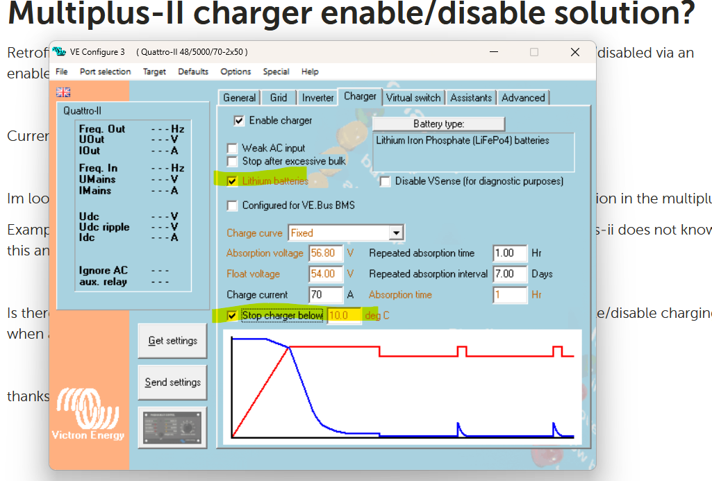
Im looking for a solution to automatically enable/disable the shore power charging function in the multiplus-II.

Example - battery pack temp is too cold and am plugged into shore power. The multiplus-ii does not know this and will attempt to keep charging the pack.


Is there a victron device that can communicate with the multiplus via a cerbo gx to enable/disable charging when an enable signal is present at said device?


thanks for the help!


battery charging
2 |3000

Up to 8 attachments (including images) can be used with a maximum of 190.8 MiB each and 286.6 MiB total.

2 Answers
klim8skeptic avatar image
klim8skeptic answered ·

@Supahdave Example - battery pack temp is too cold and am plugged into shore power. The multiplus-ii does not know this and will attempt to keep charging the pack.

Pretty easy to set the multi as not to charge Li batteries at low temps. Use the temp sensor supplied with the multi.

temp-charge-disable.png


4 comments
2 |3000

Up to 8 attachments (including images) can be used with a maximum of 190.8 MiB each and 286.6 MiB total.

supahdave avatar image supahdave commented ·
Thats the dilemma. Internal pack temp is colder than ambient temp. Volta batteries are housed inside a metal enclosure and not sure of how to get a temp sensor inside. This is already done electronically inside the volta pack enclosure and am trying to figure out a way to use it.
0 Likes 0 ·
Alexandra avatar image Alexandra ♦ supahdave commented ·

Are you able to read the internal temps somehow? Just asking as to how you know the temp is lower in the battery than ambient.

By how much though? You could likely have the min temp set higher as an offset.


Yes there are devices that communicate temperatures.

There is the terminal one you get with the inverter.

The ruuvi...

And the ve bus bt dongle - sticks on the side of the battery to read temps there.

0 Likes 0 ·
supahdave avatar image supahdave Alexandra ♦ commented ·
Yes. I have a way to read internal temp thru the system using a phone app. The battery material is very dense and cant really set an offset since the material warms much slower than cabinet temp. There also is not a direct terminal to install a temp sensor (terminal is on the enclosure, cells are encased inside the sealed enclosure).


The charge enable on the old inverter is very similar to the remote on/off jumper on the MP. Charge enable from the inverter went to a relay inside the battery pack. When charging parameters were met, the relay would close (bms controlled) to complete the charger enable circuit.


0 Likes 0 ·
derrick thomas avatar image derrick thomas supahdave commented ·
So basically you have a 2 wire signal from the battery? I believe you can use the 2 wire bms assistant in the multi. If not, use the bms relay to a digital input of the cerbo, then use the digital input signal to control charging.
0 Likes 0 ·
supahdave avatar image
supahdave answered ·

Heres the latest:


It looks like the 2 wire cable coming from the pack is no voltage, just a closed/open circuit via a relay.


From what i have read, the max V for Aux 1/2 is 5vdc; so im thinking to setup a stepdown converter to feed 5vdc thru the relay that will feed aux1 5vdc when the charge enable relay is closed. Setup an assistant based on voltage present at aux 1….above 3vdc to enable charging, below 3 disables, something like that.


While im not entirely understanding of the open collectors, i found an interesting post that this may be possible without pushing voltage to aux 1. If the charge enable relay is closed, this closes the aux 1 circuit which triggers a low. Could this be used to setup an assistant somehow and not need to supply external 5vdc?

2 comments
2 |3000

Up to 8 attachments (including images) can be used with a maximum of 190.8 MiB each and 286.6 MiB total.

derrick thomas avatar image derrick thomas commented ·
Because you have a dry contact relay in the bms, and you have a cerbo gx already, you can connect the 2 wires relay from the bms directly to the digital input of the cerbo, no external voltage source required. Then you can use node red to enable/disable charging based in the state of the digital input. This would also enable you to control charging based on any other conditions you might like as well, using node red.
0 Likes 0 ·
supahdave avatar image supahdave derrick thomas commented ·
Thank you! I have some learning to do!
0 Likes 0 ·