question

pierrick-ausseresse avatar image
pierrick-ausseresse asked

VRM - DC readings are more than 10X off the mark.

Hi all,

I know the DC reading on VRM are estimated value from baterry and inverter reading and thus are not very accurate.

I have a system where the DC reading are compltely off the mark. Maybe it's just me not understanding the way the VRM shows data, but it'S hard to make use of them as it is.


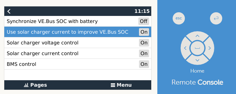
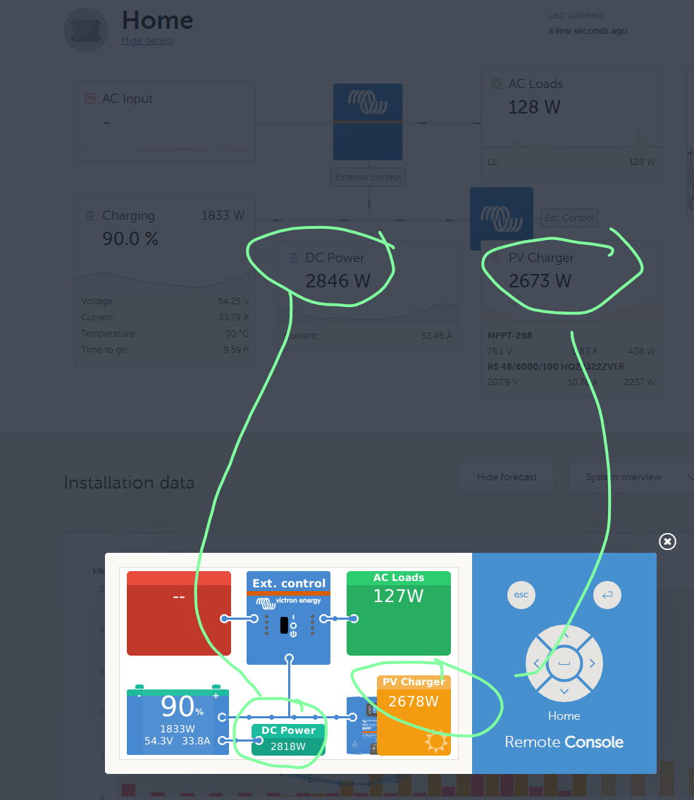
I have a system with DC loads (setting is activated in VRM). At the time of the screnshot, 300W (high quality DC Hall current clamp + volt metter on battery).

Solar is 2986W - which is quite accurate (measured less than 5% error)

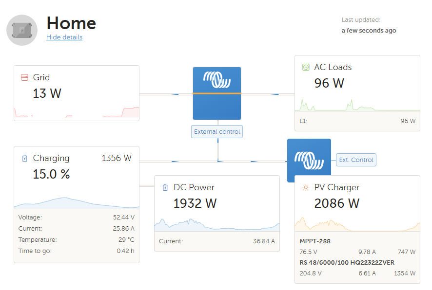
grid is 18W, AC loads 115W (shelly power metters). that's low range for the tool, I consider that good accuracy.

Battery charge with 26A (clamp) and report charging with 25.86A using it's internal shunt - same as VRM reading.There are no loads between the battery pack and it's shunt.

there is not additionnal shunts in the system.

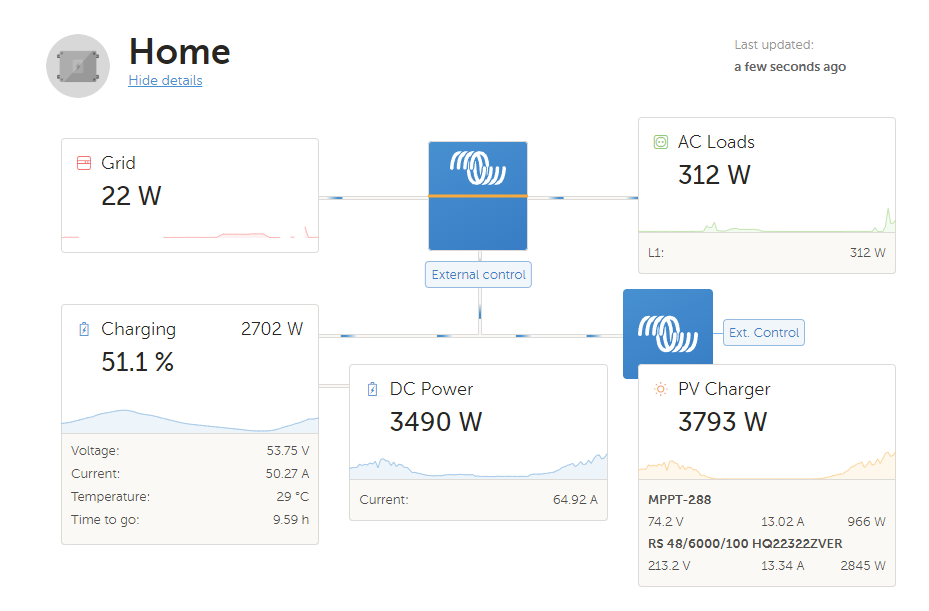
that being said I cannot make sence of the power shown below.

1715327819974.png

I expect DC power to be around 300W - maybe 200W to 400W considering up to 100W error.

2086W - 96W (AC load) -1356W (battery charing power) +13W (grid is suppling power) = 647W. it's off but it's not that far away. But 1932W ????? where is that comming from ? how to you reach such value with the inputs above ?

If you add efficiency (the 2086W solar are before the charger, into the battery flow around 1980W at 95% efficiency) you end with "DC" power of 529W - even closer.


somehow, it seems that the DC power is inlcuding the battery charging power (see the corelation sun power - mostly into the battery; and DC power). but I can't get how it's calculated.

2086W-300W-96W = 1690W, not 1932W. Including efficiency reduce teh number of watts present on the DC bus - so it would make things even worse.

During the nigth the DC ready get much better with an error of 150w max.


how to you calculate DC power ?

VRMvrm bug
1715327819974.png (71.3 KiB)
2 |3000

Up to 8 attachments (including images) can be used with a maximum of 190.8 MiB each and 286.6 MiB total.

3 Answers
Alexandra avatar image
Alexandra answered ·

@Pierrick Ausseresse

It includes power moving over the DC bus. Voltage at the battery terminals will be different to the battery voltage so will calculate based on that. Since amps are mostly an unknown (no shunt) that is the guestimate part.

It is normal to have some looses due to inefficiency as well. Heat being the main one. (You seem to have that at 150W with not mppt usage)

So during the day it is 500W ish difference so could be related to dc voltage at the inverter terminals? Just a guess as i dont have data.

Check in system set up or dvcc if mppt charge current is being used as well to 'help' calculate.

If you dont have DC loads (or a shunt to measure it) switch it off.

1 comment
2 |3000

Up to 8 attachments (including images) can be used with a maximum of 190.8 MiB each and 286.6 MiB total.

pierrick-ausseresse avatar image pierrick-ausseresse commented ·

Yes, losses seems to be at around 150W in my system for about 2000W power. It naturally gets lower with lower loads / sun but that's what I get under the condition we have.


Honestly, amps are know. Battery has a shunt and report properly. the RS 6000 also have a current sensor(shunt or hall, I do not know). MPPT100/20 also have a current sensor. All of them report currents on the DC bus plus minus 5% which is am engineer feat knowing how hard it is to accuratly measure large currents. only one missing is the DC load (which doesn't report to VRM)

Now if you sum the DC bus currents with sign, the remaing value is the net remaining current for all that is not measured - and it's not a guestimate but the true "DC load". That would have been around 6A in my case.

This does not even requiere considering efficiency ! The amperes coming out of the RS into the battery have already been reduce due to losses.


To answer your questions

At the amperage above I have around 150mV drop on each cable for a total of 300mV.

We're talking about 0.6% voltage loss (which in this case is also 0.6% efficiency loss as current remain the same along the cable)


for the charge current being used in calculation, do you mean this :

1715332540392.png


lastly when you say "switch it OFF" after talking about DVCC, you most likely refered to the "DC load" option, rigth ?

0 Likes 0 ·
1715332540392.png (30.5 KiB)
JohnC avatar image
JohnC answered ·

I think this may be a bug, perhaps something overlooked when the RS 48/6000 was introduced. The RS makes it into the 'PV Charger' tile, but it's W value may not be being used in the 'DC Power' calcs.

@Pierrick Ausseresse You see the changing values, would that account for the differences you see over a longer time?

Also, is it the same in Remote Console?

1 comment
2 |3000

Up to 8 attachments (including images) can be used with a maximum of 190.8 MiB each and 286.6 MiB total.

pierrick-ausseresse avatar image pierrick-ausseresse commented ·

Hi,

now that you say it the RS solar output seems to be going into the DC load section on top of any DC load. DC power (+10%) = RS(solar) + DC load

Variation of the DC load are quite accuratly reproduced in the VRM.

1) DC load set to 200W

1715340949369.png

2) DC load set to 350W

1715341025408.png

3) 350W DC load, MPPT100/20 deactivated.

1715341644565.png

I didn't find a "deactivate charger" on the victron connect page (bluetooth) of the RS (only an ON/OFF that I believe is for the whole system - I can't deactivate the inverter).

If there is I could also do this test; if you want me to.


what do you mean with the remote console ?

I have only one system with 2 charger and one GX device.

0 Likes 0 ·
1715341025408.png (66.5 KiB)
1715341644565.png (65.3 KiB)
JohnC avatar image
JohnC answered ·

@Pierrick Ausseresse

Good work there, thanks for the report. I think that's the problem, so I'll escalate it to see if someone can take a look. Mightn't be a quick fix though.

By Remote Console I mean the local GUI you get when you hit the 'esc' button. I'd expect it to be the same, but confirm that if you can. If it's there it's a VenusOS/GX thing, not VRM.

4 comments
2 |3000

Up to 8 attachments (including images) can be used with a maximum of 190.8 MiB each and 286.6 MiB total.

pierrick-ausseresse avatar image pierrick-ausseresse commented ·

somehow one screenshot got lost during the update. Need to take them again (wasn't saved localy)

200W DC load : 2759W * 1.1 = 3236W - 200W (diff 4.4W)

1715342090322.png

350W DC load : 2742W*1,1 = 3336W - 350W (diff 30W)1715342190300.png


Alltogether there is good corelation between the solar production of the Multi RS and the DC load offset.


0 Likes 0 ·
1715342090322.png (69.4 KiB)
1715342190300.png (68.5 KiB)
pierrick-ausseresse avatar image pierrick-ausseresse commented ·

you mean that :

1715350564510.png

the remote console is updated by second so there are some difference to the VRM (1minute) but it's minimum

I use the remote console from VRM website. My Venus base GX device running V3.00 on raspberry Pi 4, 8GB is connected on a dedicated VLAN. The VRM website is more practicall for daily use.

PS :

the equation above is still valid : RS(solar) *1,1 + DC load = DC power => 2237W*1,1+350W = 2846W (error 35W)


BR,

Pierrick

0 Likes 0 ·
1715350564510.png (158.4 KiB)
JohnC avatar image JohnC ♦ pierrick-ausseresse commented ·
@Pierrick Ausseresse

What firmwares are you running on the GX and RS? If they're not current try updating them to the latest releases.

Note to myself - never assume fw is up to date..

0 Likes 0 ·
pierrick-ausseresse avatar image pierrick-ausseresse JohnC ♦ commented ·

MPPT and RS were up to date. GX wasn't updated, now it is done. I lost remote console on vrm after the update (Connecting .... without end), I will need to debug that - but at least I can tell reporting in VRM is unchanged.

FW version used :

Device FW
GX 3.31
RS 1.16
MPPT 1.63


BR,

Pierrick

0 Likes 0 ·

Related Resources